Page 1037 of 1216
AUTOMATIC TRANSAXLE- Transfer Case Sub Assembly 21-343
7.13. SPACER(S) SELECTION
(1) First install the spacers used up to this time and then
assemble the transfer case subassembly.
(2) Using the special tool, measure the rotating drive
torque of the drive bevel gear and select spacer(s) so it
reaches the standard value.Standard value:
1.7-2.5 Nm (1.23-1.81 ft.lbs.)CautionSelect
spacers of nearly same thickness on both
sides.
Page 1039 of 1216
22-l-.
WHEELS
AND TIRES
CONTENTSNZZAA-
SERVICE ADJUSTMENT PROCEDURES.......4TROUBLESHOOTING......................................3
Tire
InflationPressureCheck......................4Bald Spots
TireWearCheck..........................................4Cracked Treads
Wheel
RunoutCheck...................................4Feathered Edge
SPECIFICATIONSRapid Wear at Center.............................................2
General
Specifications..................................2Rapid Wear at Shoulders
ServiceSpecificationsScalloped Wear...................................2Wear on One Side
7TorqueSpecifications...................................2
WHEEL AND TIRE..........................................5
Page 1040 of 1216
5 22-2WHEELS AND TIRES - Specifications
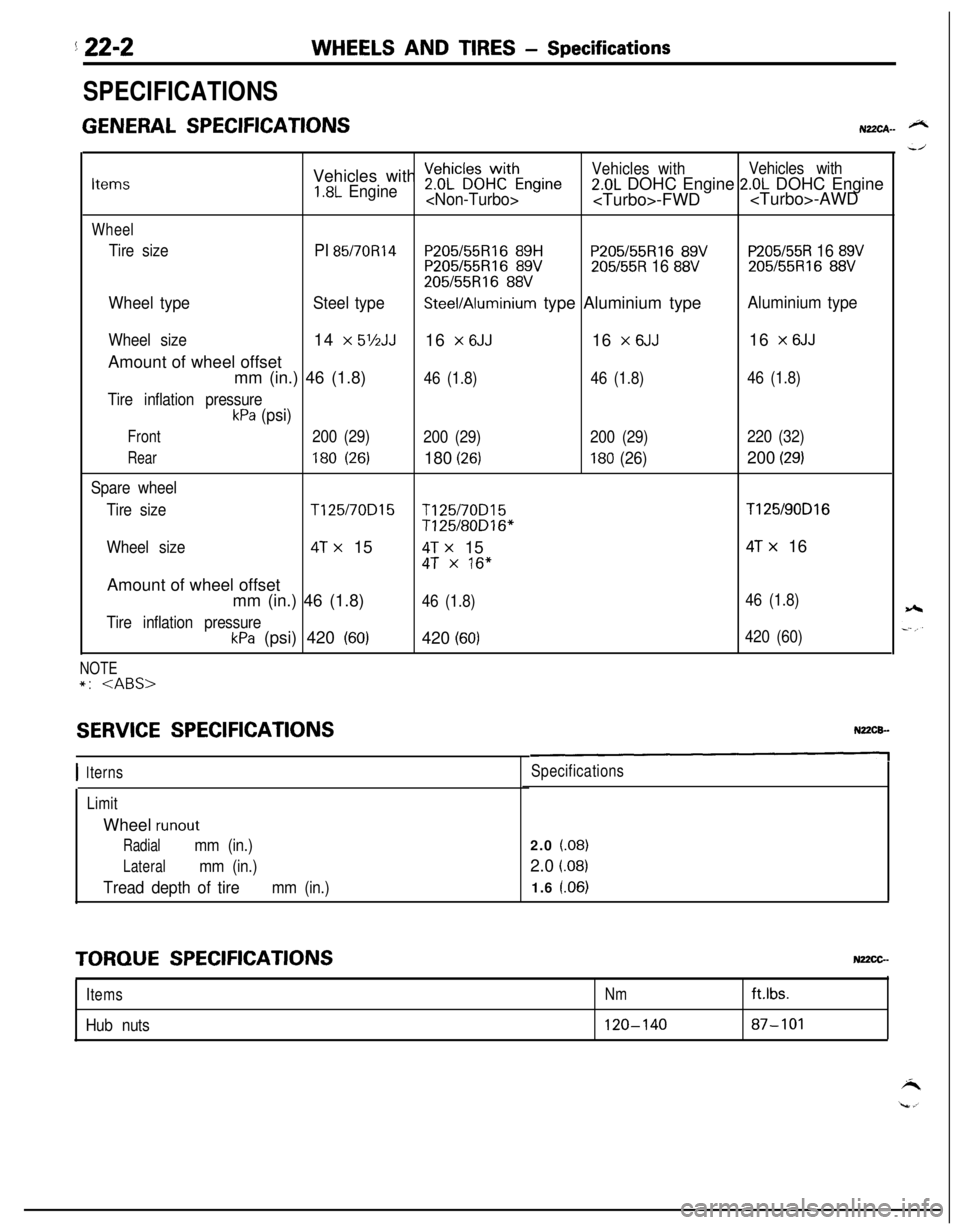
SPECIFICATIONS
GENERAL SPECIFICATIONSN22CA- @NVehicles with
~eDhL”~~HWCthEngineVehicles withVehicles withItems1.8L Engine2.0L DOHC Engine 2.0L DOHC Engine-FWD-AWD
Wheel
Tire sizePI 85/70R14P205155Rl6 89HP205/55R16 89VP205/55R 16 89VP205155R16 89V205/55R 16 88V205/55R16 88V
205/55R16 88V
Wheel typeSteel typeSteel/Aluminium type Aluminium typeAluminium type
Wheel size14 x 5’/2JJ16 x 6JJ16 x 6JJ16 x 6JJAmount of wheel offset
mm (in.) 46 (1.8)
46 (1.8)46 (1.8)46 (1.8)
Tire inflation pressure
kPa (psi)
Front200 (29)
200 (29)200 (29)220 (32)
Rear180 (26)180 (26)180 (26)200 (29)
Spare wheel
Tire size
T125/70D15T125/70D15T125/90D16
T125/80D16*
Wheel size
4T x 154T x 154T x 16
4T x 16”Amount of wheel offset
mm (in.) 46 (1.8)
46 (1.8)46 (1.8)
Tire inflation pressure
kPa (psi) 420 (60)420 (60)420 (60)
NOTE*:
SERVICE SPECIFICATIONS
I 1terns
LimitWheel
runout
Radialmm (in.)
Lateralmm (in.)
Tread depth of tiremm (in.)
Specifications2.0
(.08)2.0
i.08)1.6 l.06)
TORQUE SPECIFICATIONSNz2cG-
ItemsNm
Hub nuts120-140ftlbs.87-101
Page 1045 of 1216
23-lBODY
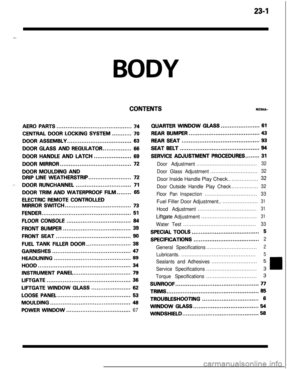
CONTENTSN23Ak-
AERO PARTS..........................................74
CENTRAL DOOR LOCKING SYSTEM...........70
DOOR ASSEMBLY....................................63
DOOR GLASS AND REGULATOR................66
DOORHANDLEANDLATCH.....................69
DOOR MIRROR........................................72
DOOR MOULDING AND
DRIP LINE WEATHERSTRIP........................72
....DOOR RUNCHANNEL...............................71
DOOR TRIM AND WATERPROOF FILM........65
ELECTRIC REMOTE CONTROLLED
MIRROR SWITCH.....................................73
FENDER..................................................51
FLOOR CONSOLE....................................84
FRONT BUMPER......................................39
FRONT SEAT..........................................90
FUEL TANKFILLERDOOR.........................38
GARNISHES............................................47
HEADLINING...........................................89
HOOD....................................................34
INSTRUMENT PANEL................................79
LIFTGATE...............................................36
LIFTGATE WINDOWGLASS......................62
LOOSE PANEL.........................................53
MOULDING.............................................48
POWER WINDOW....................................67
QUARTERWINDOWGLASS......................61
REAR BUMPER........................................43
REAR SEAT............................................93
SEAT BELT.............................................94
SERVICE ADJUSTMENT PROCEDURES........31
Door Adjustment....................................32
Door Glass Adjustment............................32Door Inside Handle Play Check..................
32
Door Outside Handle Play Check................32
Floor PanInspection...............................
33Fuel Filler Door Adjustment.......................
31
Hood Adjustment...................................31
Liftgate Adjustment.................................31
Water Test...........................................33
SPECIAL TOOLS......................................5
SPECIFICATIONS.....................................2
General Specifications..............................
2
Lubricants.............................................5
Sealants and Adhesives...........................5
Service Specifications..............................3
Torque Specifications..............................3
SUNROOF...............................................77TRIMS
....................................................85
TROUBLESHOOTING................................6WINDOW
GLASS.....................................54
WINDSHIELD...........................................58
Page 1047 of 1216
BODY - Specifications23-3
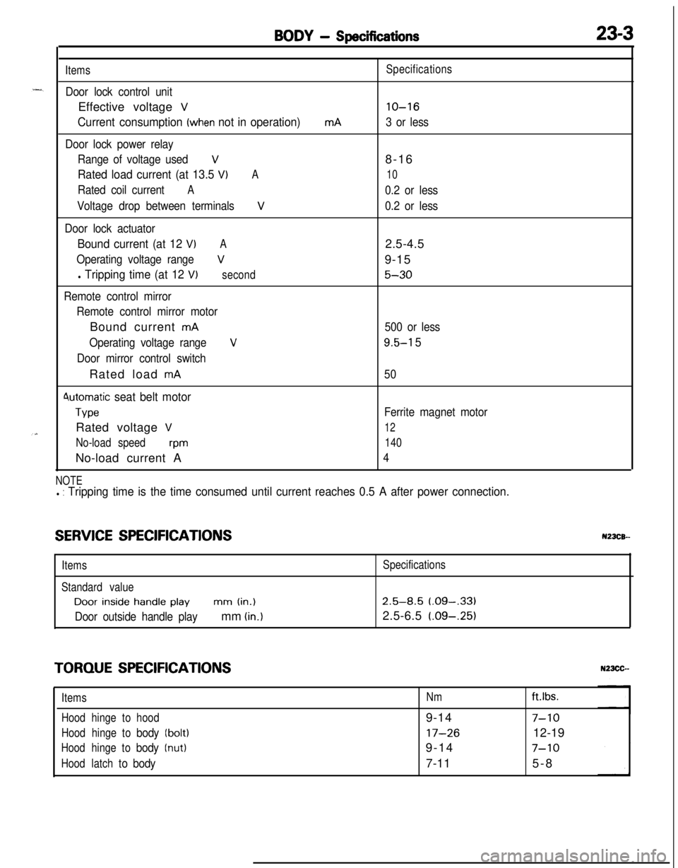
Items
Door lock control unitEffective voltage
V
Current consumption (when not in operation)
Door lock power relay
Range of voltage used
V
Rated load current (at 13.5 VIA
Rated coil currentA
Voltage drop between terminalsV
Door lock actuator
Bound current (at 12 VIA
Operating voltage rangeV
l Tripping time (at 12 V)second
Remote control mirror
Remote control mirror motorBound current
mA
Operating voltage range
V
Door mirror control switchRated load
mA
4utomatic seat belt motor
TypeRated voltage
V
No-load speedwmNo-load current A
mASpecifications
lo-16
3 or less8-16
10
0.2 or less
0.2 or less2.5-4.5
9-15
5-30
500 or less
9.5-l 5
50
Ferrite magnet motor
12
140
4
NOTEl : Tripping time is the time consumed until current reaches 0.5 A after power connection.
SERVICE SPECIFICATIONSN23CB--
ItemsSpecifications
Standard valueDoor
inside handle playmm (in.)2.5-8.5 (.09-,331
Door outside handle playmm (in.)2.5-6.5 (.09-.25)
TORQUE SPECIFICATIONS
ItemsNmft.lbs.
Hoodhingetohood9-14
7-10
Hoodhingetobody(bolt)17-2612-19
Hoodhingetobody(nut)9-147-10
Hoodlatchtobody7-115-8
Page 1095 of 1216
BODY - Fender
FENDER
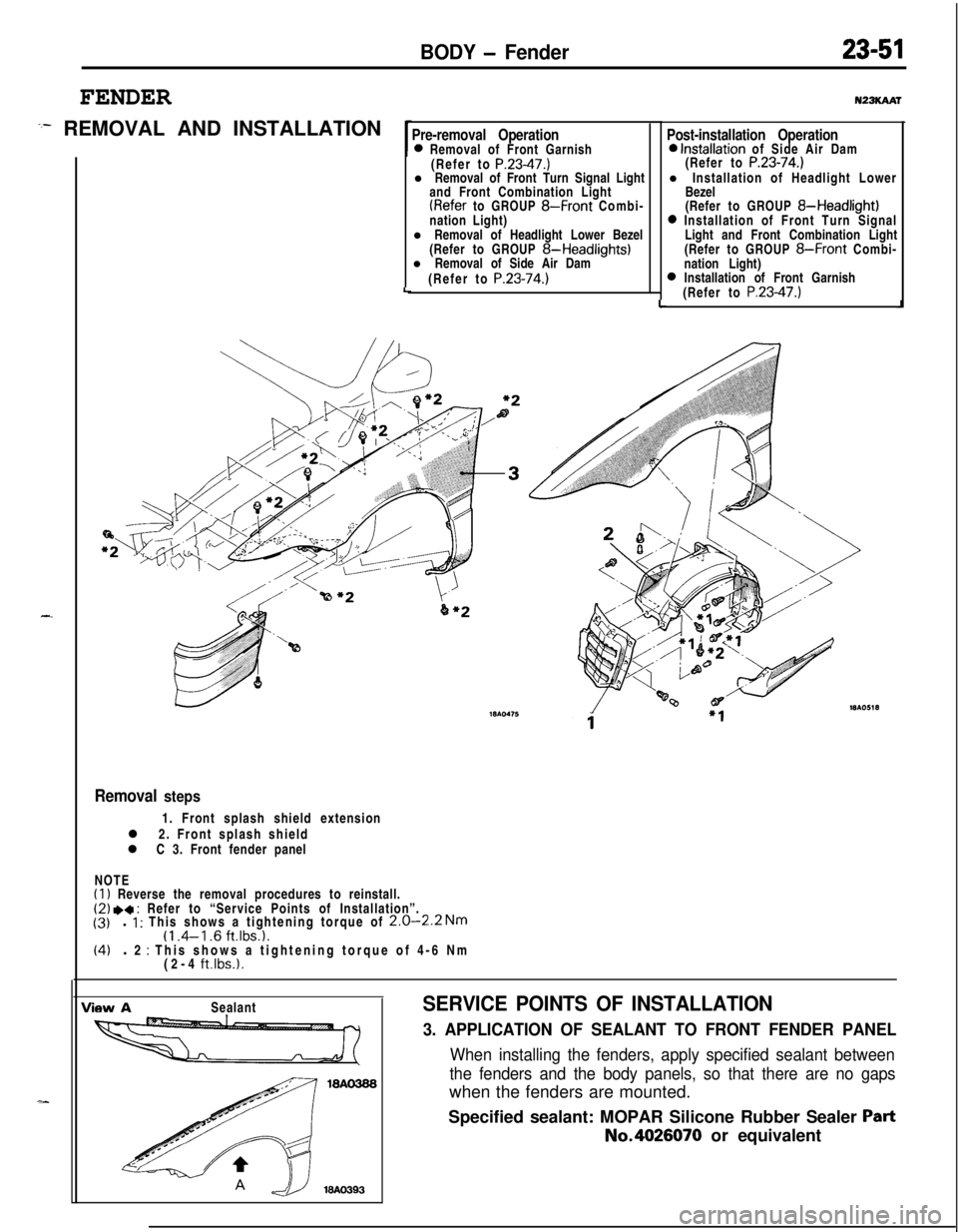
:- REMOVAL AND INSTALLATION
-.
Pre-removal Operation0 Removal of Front Garnish
(Refer to P.23-47.)l Removal of Front Turn Signal Light
and Front Combination Light
(Refer to GROUP 8-Front Combi-
nation Light)
l Removal of Headlight Lower Bezel
(Refer to GROUP
8-Headlights)l Removal of Side Air Dam
(Refer to
P.23-74.)LLu23KAAr
Post-installation Operation0 Installation of Side Air Dam
(Refer to P.23-74.)l Installation of Headlight Lower
Bezel
(Refer to GROUP
8-Headlight)0 Installation of Front Turn Signal
Light and Front Combination Light
(Refer to GROUP
8-Front Combi-
nation Light)
0 Installation of Front Garnish
(Refer to P.23-47.)J
Removal steps1. Front splash shield extension
l 2. Front splash shield
l C 3. Front fender panel
NOTE
(1) Reverse the removal procedures to reinstall.(2) .a : Refer to “Service Points of Installation”.
(3)l 1 : This shows a tightening torque of 2.0-2.2 Nm(1 .4-l .6 ft.lbs.1.(4)l 2 : This shows a tightening torque of 4-6 Nm
(2-4 ft.lbs.1.
View ASealantSERVICE POINTS OF INSTALLATION
3. APPLICATION OF SEALANT TO FRONT FENDER PANEL
When installing the fenders, apply specified sealant between
the fenders and the body panels, so that there are no gapswhen the fenders are mounted.
Specified sealant: MOPAR Silicone Rubber Sealer
PartNo.4026070 or equivalent
Page 1135 of 1216
-
BODY - Front Seat23-91
Bolts
19AO308
FrontFront seat forward
installation bracket
A-A cross-section
Forward tab
.)\&Front seat’s rearz-2 bracketarea mounting
1Lanchor\
coverForward tabB-B cross-section19A0124
Slid; railSlide kail’sreararea mounting
bracketWA0302
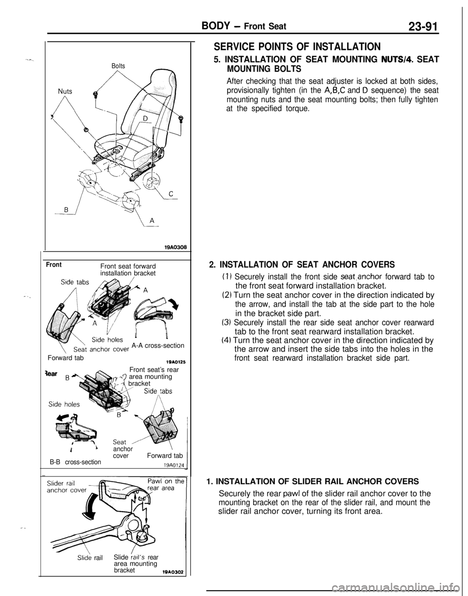
SERVICE POINTS OF INSTALLATION
5. INSTALLATION OF SEAT MOUNTING NUTW4. SEAT
MOUNTING BOLTS
After checking that the seat adjuster is locked at both sides,
provisionally tighten (in the
A,B,C and D sequence) the seat
mounting nuts and the seat mounting bolts; then fully tighten
at the specified torque.
2. INSTALLATION OF SEAT ANCHOR COVERS
(1) Securely install the front side seat.anchor forward tab tothe front seat forward installation bracket.
(21 Turn the seat anchor cover in the direction indicated by
the arrow, and install the tab at the side part to the holein the bracket side part.
(3) Securely install the rear side seat anchor cover rearwardtab to the front seat rearward installation bracket.
(4) Turn the seat anchor cover in the direction indicated by
the arrow and insert the side tabs into the holes in the
front seat rearward installation bracket side part.1. INSTALLATION OF SLIDER RAIL ANCHOR COVERS
Securely the rear
pawl of the slider rail anchor cover to the
mounting bracket on the rear of the slider rail, and mount theslider rail anchor cover, turning its front area.
Page 1143 of 1216
BODY - Seat Belt23-99
19AO239
I ITest bulb 2tI
I I
INSPECTION
SEAT BELT TIMERRemove the seat belt timer from the relay box (indoor).
TIMER OPERATION CHECK(I
1 Connect the battery and the test bulb to the timer, as shown
in the illustration.
(2) Make sure that when terminal 2 is connected to the positive
(+) terminal of the battery, test bulbs 1 and 2 are lighted
for approx. 6 seconds.
(3) Make sure that even when terminal 3 is disconnect while testbulbs 1 and 2 and lighted in
(2) above, test bulb 1 remains
lighted.
BUCKLE SWITCHRefer to
P.23-97.
BUZZERRefer to
P.23-97.
SERVICE POINTS OF INSTALLATION7. INSTALLATION OF FRONT SEAT BELT
Fit the retractor retaining lug in the slot provided in the
vehicle body, and secure the retractor with the bolt by
tightening it to the specified torque.