Page 363 of 1216
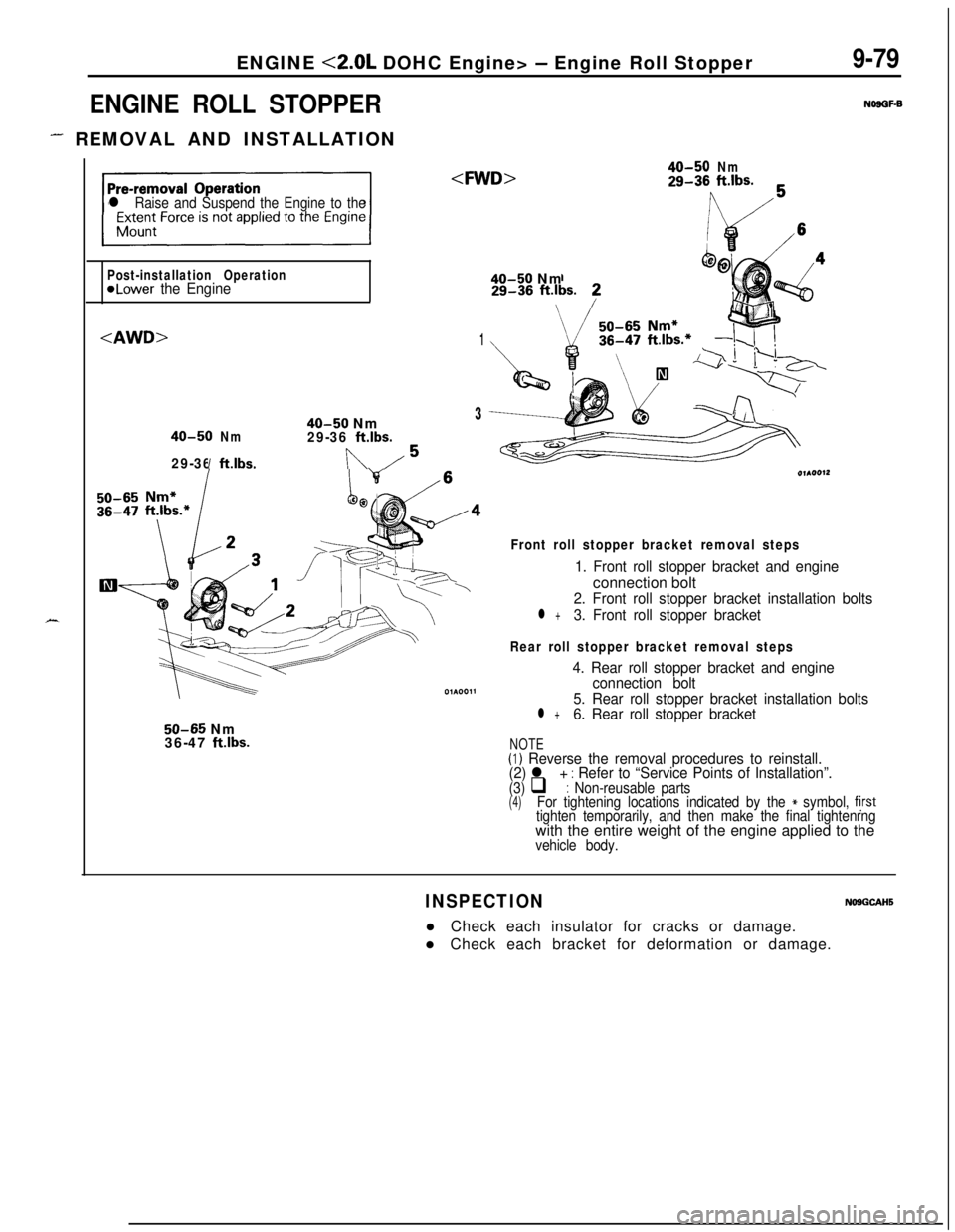
ENGINE <2.0L DOHC Engine> - Engine Roll Stopper
ENGINE ROLL STOPPER
- REMOVAL AND INSTALLATION
9-79
NOSGF-B
X
l Raise and Suspend the Engine to the
40-50Nm29-36ft.lbs.
Post-installation Operation
@Lower the Engine40-50 Nm
1
40-50 Nm3
40-50Nm29-36ft.lbs.
29-36ft.lbs.In/5
/4
\
50-65 Nm
36-47 ftlbs.
Front roll stopper bracket removal steps
1. Front roll stopper bracket and engineconnection bolt
2. Front roll stopper bracket installation bolts
l +3. Front roll stopper bracket
Rear roll stopper bracket removal steps
4. Rear roll stopper bracket and engine
connection bolt
5. Rear roll stopper bracket installation bolts
l +6. Rear roll stopper bracket
NOTE(I) Reverse the removal procedures to reinstall.
(2) l + : Refer to “Service Points of Installation”.(3) q : Non-reusable parts(4)For tightening locations indicated by the * symbol, fjrsttighten temporarily, and then make the final tightenrngwith the entire weight of the engine applied to the
vehicle body.
INSPECTIONNOSGCAHSl Check each insulator for cracks or damage.
l Check each bracket for deformation or damage.
Page 366 of 1216
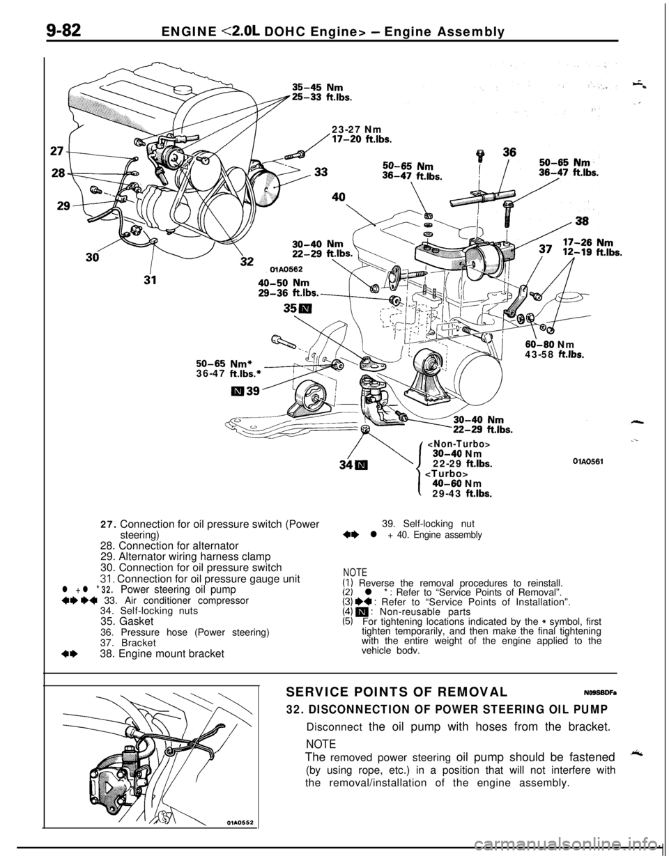
9-82ENGINE <2.0L DOHC Engine> - Engine Assembly
23-27 Nm
/17-20 ftlbs.
60-60 Nm
43-58 ft.lbs.50-65 Nm*36-47 ft.lbs.*27. Connection for oil pressure switch (Power
steering)28. Connection for alternator
29. Alternator wiring harness clamp
30. Connection for oil pressure switch
31, Connection for oil pressure gauge unitl + l * 32.Power steering oil pump+9 ~~ 33. Air conditioner compressor
34. Self-locking nuts
35. Gasket
36. Pressure hose (Power steering)
37. Bracket
4*38. Engine mount bracket
30-40 Nm
22-29 ftlbs.
.--
OlAO561
1
I40-60 Nm
29-43 ft.lbs.39. Self-locking nut
+e l + 40. Engine assembly
NOTE(I) Reverse the removal procedures to reinstall.(2) l * : Refer to “Service Points of Removal”.(3) I)+ : Refer to “Service Points of Installation”.(4) m : Non-reusable parts(5)For tightening locations indicated by the * symbol, first
tighten temporarily, and then make the final tightening
with the entire weight of the engine applied to the
vehicle bodv.
SERVICE POINTS OF REMOVALNOSSBDFa
32. DISCONNECTION OF POWER STEERING OIL PUMPDisconnect the oil pump with hoses from the bracket.
NOTEThe removed power steering oil pump should be fastened
A(by using rope, etc.) in a position that will not interfere with
the removal/installation of the engine assembly.
Page 371 of 1216

ENGINE <2.0L DOHC Engine> -Camshafts and Camshaft Oil Seals/Oil Pan and Oil Screen9-87
7. INSTALLATION OF ROCKER COVERApply a coating of the specified sealant where shown in
the figure, and then install the rocker cover to the cylinder
head assembly.
Apply sealant
mmin.)
Specified sealant: MOPAR Part No.4318034
or equivalent
olmO47
2. INSTALLATION AND ADJUSTMENT OF TIMING BELTRefer to
P.9-104.
1. ADJUSTMENT OF ACCELERATOR CABLERefer to GROUP 14-Service adjustment procedures.
OIL PAN AND OIL SCREENNO9HA-BREMOVAL AND INSTALLATION
/
/j<&(Refer to GROUP O-Maintenance
\ I/“!18
III13
12-
Removal steps
1.Drain plug2.Self locking nut15-22Nm3.Centermember11-16ft.lbs.7. Connection for exhaust pipe
8.Gasket
9. Connection for oil return pipe (Turbo:IO. Gasket (Turbo)
l * l * 11.Oil pan12.Oil screen
13.Gasket
50-65 Nm*36-47 ft.lbs.*
/117‘1
35-45 NmI25-33 ft.ll3s.
NOTE(I) Reverse the removal procedures to reinstall.(2) l e : Refer to “Service Points of Removal”.
(3) l + : Refer to “Service Points of Installation”.
(4) m : Non-reusable parts
(5)For tightening locations indicated by the * symbol, firsttighten temporarily, and then make the final trghtenrngwith the entire weight of the engine applied to the
vehicle body.
Page 634 of 1216

17-24REAR SUSPENSION - Rear Suspension Assembly
1
II
brakeA022116. REMOVAL OF REAR SUSPENSION ASSEMBLY
(1) Supporting the rear suspension assembly with a trans-
mission jack, move it toward the rear (in the direction of
wtthe fuel tank).
c1(2) Gradually lower the transmission jack, avoiding contact
with the stabilizer bar and the propeller shaft.
Caution
1. Ensure that the propeller shaft does not bend
greatly.
2.Ensure that the liibro joint does not receive any
shock.
NOTEThe lowering of the rear suspension assembly from the
transmission jack requires three individuals due to the
amount of weight being handled (one on the differen-
tial, and one on either side of the lower arm).
(3) In order to protect the rear suspension assembly dust
shield, support the lower arm ball joint with a wooden
block.
INSPECTIONNl7GCAMl Check crossmember for cracks or other damage.
SERVICE POINTS OF INSTALLATIONN17GOAR -
8.INSTALLATION OF PROPELLER SHAFT INSTALLATIONBOLT AND NUT
Install the propeller shaft to the differential carrier, ensuringthat the mating marks are aligned.
3. INSTALLATION OF PARKING BRAKE CABLE END
NOTE
Connecting a parking brake cable end to parking brake lever
and prying up the parking brake lever, the installation of theother cable end will be easy.
’ice,
Page 713 of 1216
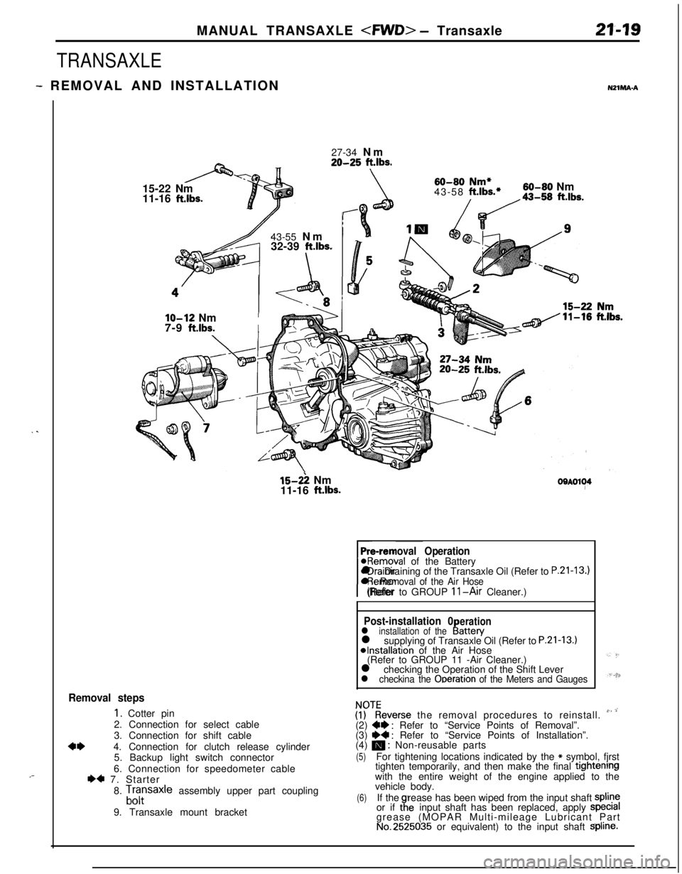
MANUAL TRANSAXLE - Transaxle21-19
TRANSAXLE
- REMOVAL AND INSTALLATIONNZlMA-A
. .
,-27-34 Nm
20-25 ft.lbs.15-22 Nm
11-16
ft.lbs.43-55 Nm
32-39
ft.lbs.
\
60-80 Nm*43-58 ft.lbs.*60-80 Nm
/da-,, ft.lbs.
lo-12 NmI7-9
ft.lbs.I
15-2: Nm
11-16 ft.lbs.OOAOl~4
Pre-removal Operation@Removal of the Battery
rl Draining of the Transaxle Oil (Refer to
P.21-13.)l Removal of the Air Hose(Refer to GROUP 11-Air Cleaner.)
Post-installation 0erationl installation of theI!attery
l supplying of Transaxle Oil (Refer to P.21-13.)*Installation of the Air Hose
(Refer to GROUP 11 -Air Cleaner.)
l checking the Operation of the Shift Lever
l checkina the Ooeration of the Meters and Gauges
Removal steps
1. Cotter pin
2. Connection for select cable
3. Connection for shift cable
4*4. Connection for clutch release cylinder
5. Backup light switch connector
6. Connection for speedometer cable
I)* 7. Starter
8.
Lfrsaxle assembly upper part coupling
9. Transaxle mount bracket
ZKeverse the removal procedures to reinstall. ” ’(2) W : Refer to “Service Points of Removal”.
(3) ~~ : Refer to “Service Points of Installation”.
(4) m : Non-reusable parts
(5)For tightening locations indicated by the * symbol, fjrst
tighten temporarily, and then make the final tightenrngwith the entire weight of the engine applied to the
vehicle body.
(6)If therease has been wiped from the input shaft spline
or if taeinput shaft has been replaced, apply specralgrease (MOPAR Multi-mileage Lubricant Part
No.2525035 or equivalent) to the input shaft Spline.
Page 776 of 1216
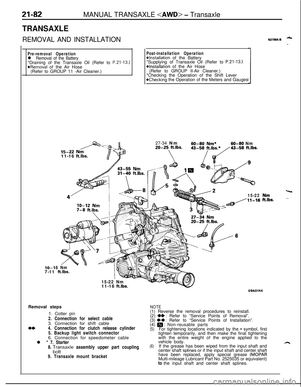
21-82MANUAL TRANSAXLE - Transaxle
TRANSAXLE
REMOVAL AND INSTALLATION
Pre-removal Operationl Removal of the Battery*Draining of the Transaxle Oil (Refer to P.Zl-13.)
@Removal of the Air Hose
(Refer to GROUP 11 -Air Cleaner.)IO-1
7-1111-16
ftlbs.
Post-installation Operation@Installation of the Battery
*Supplying of Transaxle Oil (Refer to P.21-13.)*Installation of the Air Hose
(Refer to GROUP II-Air Cleaner.)
*Checking the Operation of the Shift Lever
@Checking the Operation of the Meters and Gauges
27-34 Nm
60-60 Nm*60-80 Nm20-25 ft.lbs.
\
43-58/t.,b~43-58 ft.lbs.
15-22
6 Nm
ftlbs.
15-22 Nm
vt11-16
ft.lbs.Removal steps
1. Cotter pin
2. Connection for select cable
3. Connection for shift cable
*I)4. Connection for clutch release cylinder
5. Backup light switch connector
6. Connection for speedometer cable
l * 7. Starter
8.
A;;saxle assembly upper part coupling
9. Transaxle mount bracket
NZlMA-B -
,“rr,s.
09AOl44
NOTE(1) Reverse the removal procedures to reinstall.
(2)
+e : Refer to “Service Points of Removal”.
(3) I)+ : Refer to “Service Points of Installation”.
(4) m : Non-reusable parts(5)For tightening locations indicated by the * symbol, first
tighten temporarily, and then make the final tightening
with the entire weight of the engine applied to the
(6)vehicle body.
If the grease has been wiped from the input shaft and
center shaft splines or if the input shaft and center shaft
have been replaced, apply special grease
(MOPARMulti-mileage Lubricant Part No. 2525035 or equivalent)
to the input shaft and center shaft splines.
Page 1043 of 1216
WHEELS AND TIRES - Wheel and Tire22-5
WHEEL AND TIRE
- REMOVAL AND INSTALLATIONSteel typeAluminium type
120-140 Nm87-101 ft.lbs.
1 lA0267
Removal steps
1. Wheel cover 2. Center cover
I)+ 3. Hub nuts4. Center cap
5. Spring
6. Ornament
7. Balance weight
8. Tire
9. WheelNUGA-
120-140 Nm87-101 ftlbs.liA0334
o-140 Nm87-101 ft.lbs.
/llA0336
7
NOTE(1) Reverse the removal procedures to reinstall.(2) l 4 : Refer to “Service Points of Installation”
llAO2661 lAO265
SERVICE POINT OF INSTALLATIONNUGDABa
2. INSTALLATION OF HUB NUTS
On the high speed tire (205/55R16 88V) vehicle, the left andright tires are respectively specified. Attach the tires as
follows :Observe the wheel in the
P direction as illustrated, and the
direction characters will be found.
Attach the
(a Cl ROTATION LEFT SIDE) tire on the left
wheel, and the (ROTATION RIGHT SIDE
DD) tire on the
right wheel.
Page 1044 of 1216
22-6WHEELS AND TIRES - Wheel and Tire
INSTRUCTIONS FOR ALUMINUM TYPE
WHEELSUzzGfM
1. Aluminum is vulnerable to alkalies. If a vehicle
washing detergent has been used, or salt from
sea water or road chemicals has adhered, washthe vehicle as soon as possible. After washing
the vehicle, apply body or wheel wax to the
aluminum type wheels to prevent corrosion.
2. When cleaning the vehicle with steam, do not
direct steam onto the aluminum type wheels.
When tightening nuts for aluminum type
wheels, particularly observe the following:
(1) Clean the hub surface of aluminum type
wheels.(2) After finger-tightening wheel nuts, tighten
them to specifications.
(3) Do not use an impact wrench or push the
wrench by foot to tighten the wheel nuts.
(4) Do not apply oil to the threaded portions.
INSTRUCTIONS FOR TIRE CHAINS AND
SNOW TIRESNZZGGAA
1.Use tire chains only on front wheels. Do not usetire chains on rear wheels.
2. When using snow tires, use them on all four
wheels for maneuverability and safety.
INSTRUCTIONS FOR COMPACT SPARE
TIRE;c.1. The compact spare tire is designed to. save
space in the luggage compartment, and its
L’lighter weight makes it easier to use if a fiat tire
occurs.
2.The following instructions for the compact sparetire should be observed.
(1) Check the inflation pressure after installing
the spare, and adjust to the specified pres-
sure.(2) Avoid driving through automatic car washes
and over obstacles that could possibly dam-
age the vehicle’s undercarriage. Because
the tire is smaller than the original tire, car
ground clearance is slightly reduced.
(3) The compact spare tire should not be used
on any other wheels, nor should standard
tires, snow tires, wheel covers or trim rings
be used with the compact spare wheel. If
such use is attempted, damage to these
items or other vehicle components may
occur.