Page 252 of 1216
7-4COOLING - Specifications
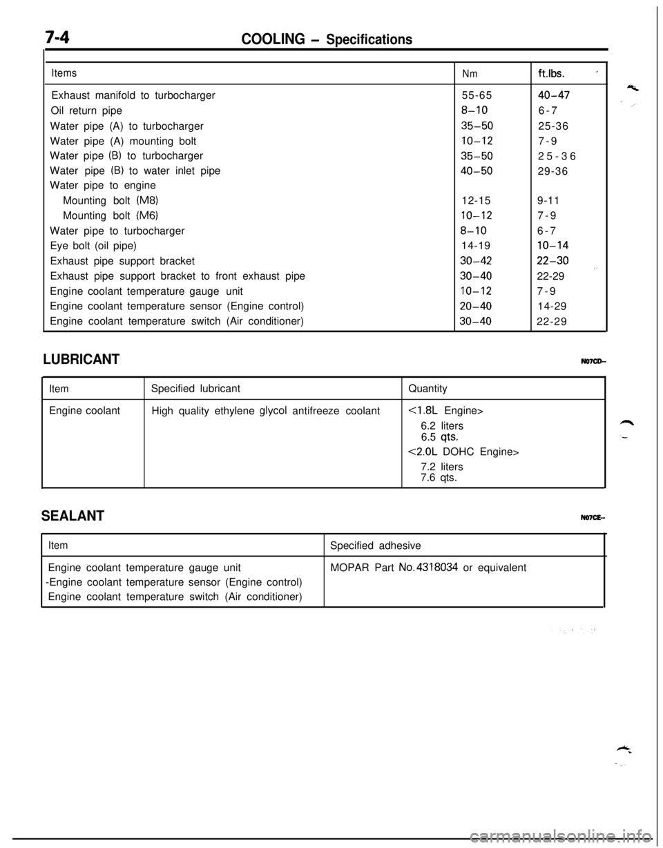
ItemsExhaust manifold to turbocharger
Oil return pipe
Water pipe (A) to turbocharger
Water pipe (A) mounting bolt
Water pipe
(B) to turbocharger
Water pipe
(B) to water inlet pipe
Water pipe to engine
Mounting bolt
(M8)Mounting bolt
(M6)Water pipe to turbocharger
Eye bolt (oil pipe)
Exhaust pipe support bracket
Exhaust pipe support bracket to front exhaust pipe
Engine coolant temperature gaugeunit
Engine coolant temperature sensor (Engine control)
Engine coolant temperature switch (Air conditioner)
Nmft.lbs. _155-65
40-47
8-106-7
35-5025-36
10-127-9
35-5025-36
40-5029-36
12-159-11
10-127-9
8-106-7
14-19
10-14
30-4222-30
30-4022-29 .’
10-127-9
20-4014-29
30-4022-29
LUBRICANT
ItemEngine coolantSpecified lubricant
High quality ethylene
glycol antifreeze coolantQuantity
6.2 liters
6.5
qts.
<2.0L DOHC Engine>
7.2 liters
7.6 qts.
SEALANTNO7CE-.
ItemEngine coolant temperature gauge unit
-Engine coolant temperature sensor (Engine control)
Engine coolant temperature switch (Air conditioner)Specified adhesive
MOPAR Part No.4318034 or equivalent
Page 253 of 1216

COOLING - Troubleshootina7-5
TRO,UBLESHOOTlNG
Symptom
OverheatProbable causeInsufficient engine coolant
Too high an anti-freeze concentrationRemedy
Replenish
Correct anti-freeze
concentration
Loose or broken drive belt
Replace
Inoperative electric cooling fan
Faulty thermosensor
Replace
Faulty electrical motorReplace
Faulty radiator fan relayReplace
Damaged or blocked (insufficiently ventilated) radiator finsCorrect
Water leaks
Damaged radiator core joint
Replace
Corroded or cracked hosesReplace
(radiator hose, heater hose, etc.)
Loose bolt or leaking gasket in water outlet fitting
(thermostat)
Loose water pump mounting bolt or leaking gasket
Faulty cap valve or setting of spring
Loose intake manifold bolts or leaking from gasket
Cracked intake manifold
Faulty automatic transaxle oil cooler operation
Blocked or collapsed hose and pipe
Loose hose and pipe connection
Faulty thermostat operation
Faulty water pump operation
Water passage clogged with slime or rust deposit or
foreign substanceCorrect or replace
Correct or replace
Replace
Retorque bolts or replace
gasket
Replace
Replace
Correct
Replace
Replace
Clean
Jo rise in temperatureFaulty thermostatReplace
Page 255 of 1216
COOLING - Troubleshooting7A7
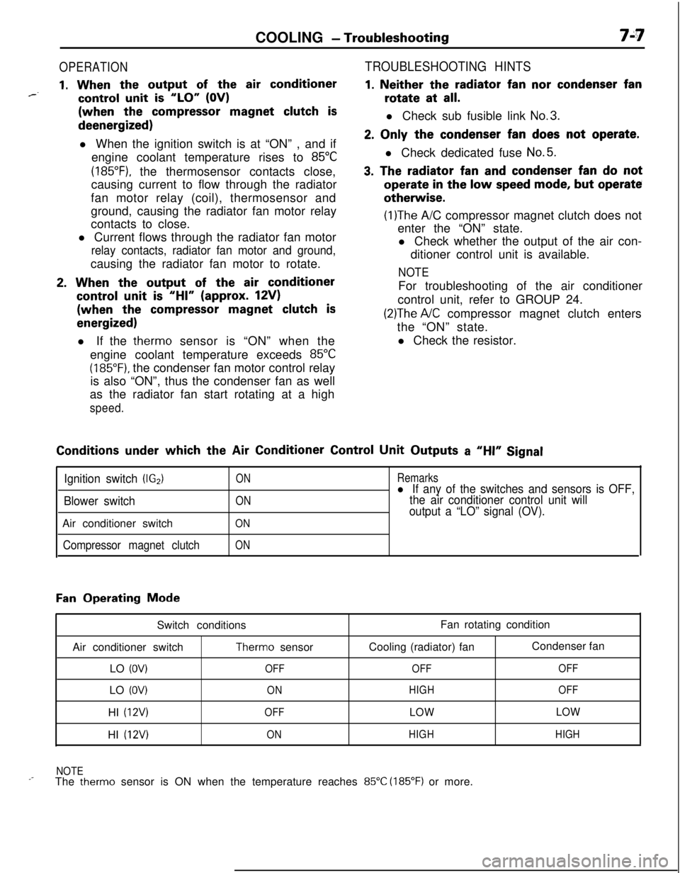
OPERATION
1. When the output of the air conditioner*--control unit is “LO” (OV)(when the
compressor magnet clutch isdeenergized)
l When the ignition switch is at “ON” , and if
engine coolant temperature rises to
85°C
(185”F), the thermosensor contacts close,
causing current to flow through the radiator
fan motor relay (coil), thermosensor and
ground, causing the radiator fan motor relay
contacts to close.
l Current flows through the radiator fan motor
relay contacts, radiator fan motor and ground,causing the radiator fan motor to rotate.
2. When the output of the air conditioner
control unit is “HI” (approx. 12V)(when the
compressor magnet clutch is
energized)l If the therm0 sensor is “ON” when the
engine coolant temperature exceeds
85°C
(185°F). the condenser fan motor control relay
is also “ON”, thus the condenser fan as well
as the radiator fan start rotating at a high
speed.
TROUBLESHOOTING HINTS
1. Neither the radiator fan nor condenser fanrotate at
all.l Check sub fusible link
No.3.
2. Only the condenser fan does not operate.l Check dedicated fuse
No.5.
3. The radiator fan and condenser fan do notoperate
in the low speed mode, but operateotherwise.
(1)The A/C compressor magnet clutch does not
enter the “ON” state.
l Check whether the output of the air con-
ditioner control unit is available.
NOTEFor troubleshooting of the air conditioner
control unit, refer to GROUP 24.
(2)The A/C compressor magnet clutch enters
the “ON” state.
l Check the resistor.Conditions
under which the Air Conditioner Control Unit Outputs a “HI” Signal
Ignition switch (IG2)
Blower switchAir conditioner switch
Compressor magnet clutch
ON
ON
ON
ON
Remarksl If any of the switches and sensors is OFF,
the air conditioner control unit will
output a “LO” signal (OV).
Fan Operating Mode
Switch conditions
Air conditioner switch
Therm0 sensor
LO
(OV)OFFLO
(OV)ONHI
(12V)OFFHI
(12V)ONFan rotating condition
Cooling (radiator) fanCondenser fan
OFFOFF
HIGHOFF
LOWLOW
HIGHHIGH
NOTE
_-The therm0 sensor is ON when the temperature reaches 85°C (185°F) or more.
Page 282 of 1216
7-34 COOLINGWater Hose and Water Pipe <2.0L DOHC Engine (Turbo)>/Engine Coolant Temperature- Gauge Unit. Engine Coolant Temoerature Sensor and Enoine Coolant Temoerature Switch
05A0026
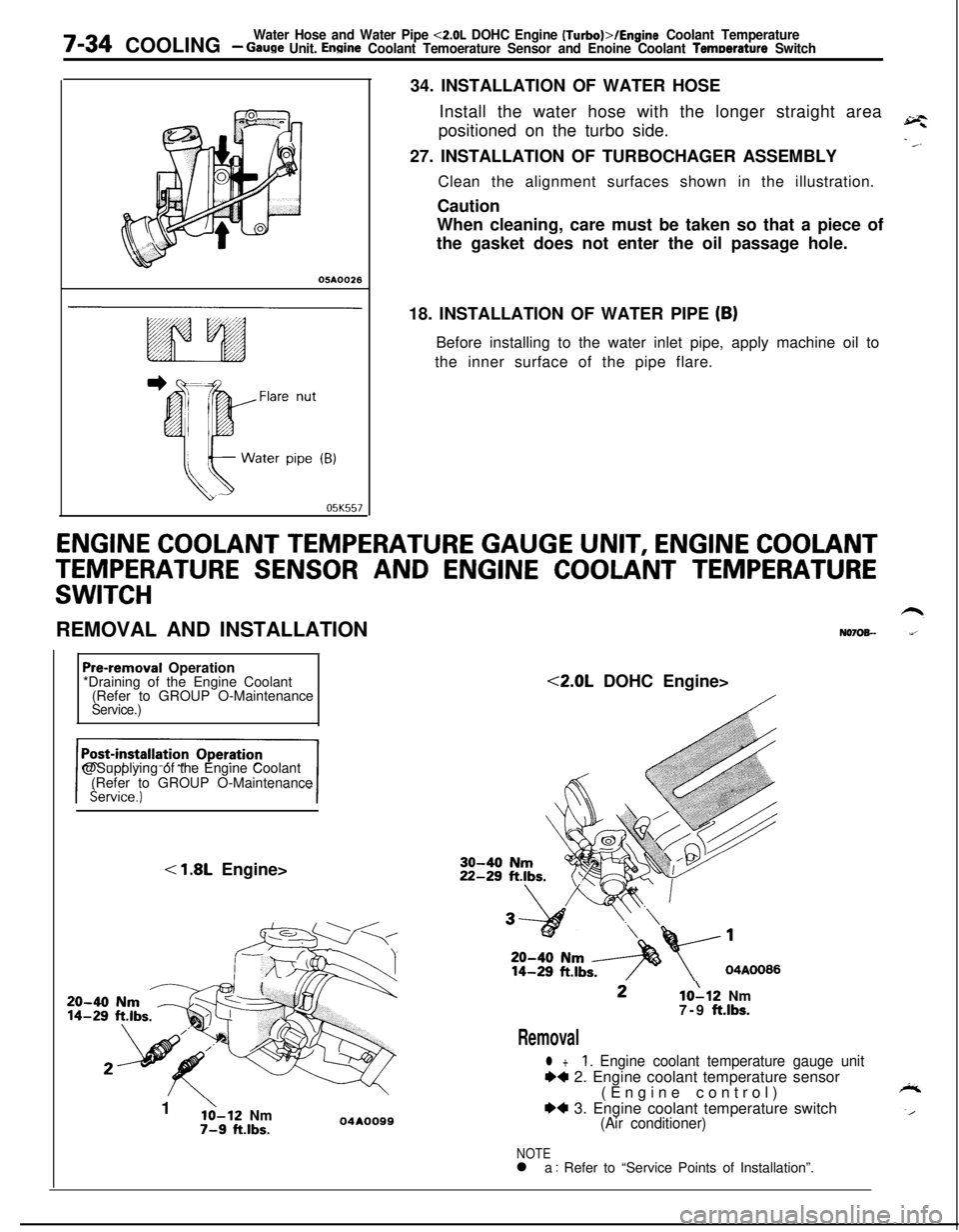
05K55734. INSTALLATION OF WATER HOSE
Install the water hose with the longer straight area
positioned on the turbo side.
27. INSTALLATION OF TURBOCHAGER ASSEMBLY
Clean the alignment surfaces shown in the illustration.
Caution
When cleaning, care must be taken so that a piece of
the gasket does not enter the oil passage hole.
18. INSTALLATION OF WATER PIPE
(B)Before installing to the water inlet pipe, apply machine oil to
the inner surface of the pipe flare.
ENGINE COOLANT TEMPERATURE GAUGE UNIT, ENGINE COOLANT
TEMPERATURE SENSOR AND ENGINE COOLANT TEMPERATURE
SWITCHREMOVAL AND INSTALLATION
N070%-
Pre-removal Operation
*Draining of the Engine Coolant
(Refer to GROUP O-Maintenance
Service.)@Supplying of the Engine Coolant
(Refer to GROUP O-Maintenance
< 1.8L Engine>
20-4014-291
’lo-12 Nm7-9 ft.lbs.04AOO99<2.0L DOHC Engine>10112 Nm
7-9 ft.lbs.
Removal
l +1. Engine coolant temperature gauge unit
++ 2. Engine coolant temperature sensor
(Engine control)
*4 3. Engine coolant temperature switch(Air conditioner)
NOTEl a : Refer to “Service Points of Installation”.
Page 283 of 1216
COOLINGEngine Coolant Temperature Gauge Unit, Engine Coolant- TemDerature Sensor and Enaine Coolant Temperature Switch7-35
.---
Sensor04GO033
0400032
1c0010
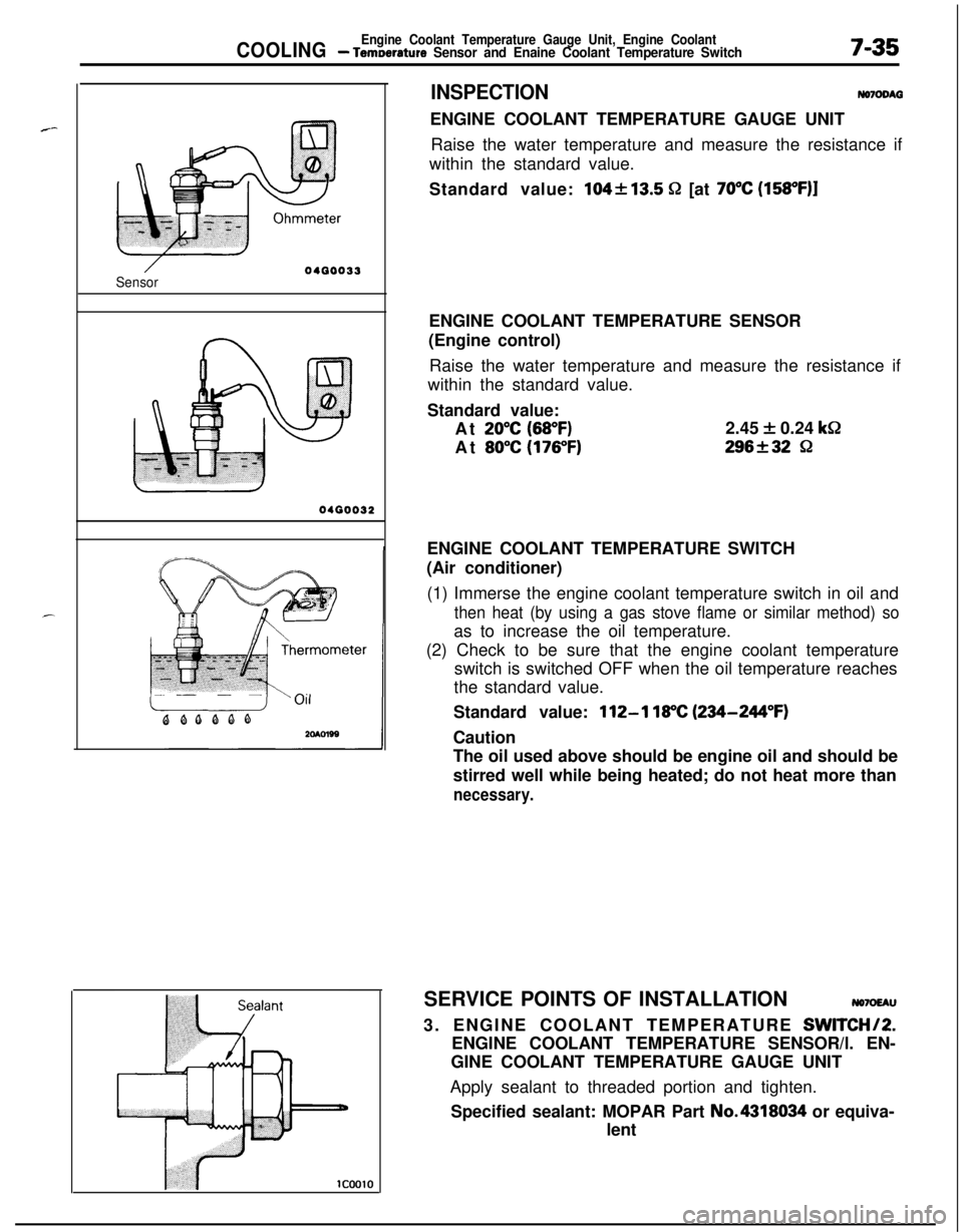
INSPECTIONNomDM3ENGINE COOLANT TEMPERATURE GAUGE UNIT
Raise the water temperature and measure the resistance if
within the standard value.
Standard value:
104213.5 52 [at 70°C (158OF)lENGINE COOLANT TEMPERATURE SENSOR
(Engine control)
Raise the water temperature and measure the resistance if
within the standard value.
Standard value:
At
20°C (68°F)2.45 + 0.24 k&
At
80°C (176°F)296f32 8ENGINE COOLANT TEMPERATURE SWITCH
(Air conditioner)
(1) Immerse the engine coolant temperature switch in oil and
then heat (by using a gas stove flame or similar method) soas to increase the oil temperature.
(2) Check to be sure that the engine coolant temperature
switch is switched OFF when the oil temperature reaches
the standard value.
Standard value:
112-l 18°C (234-244°F)Caution
The oil used above should be engine oil and should be
stirred well while being heated; do not heat more than
necessary.SERVICE POINTS OF INSTALLATION
NO7OEAU3. ENGINE COOLANT TEMPERATURE
SWITCHI2.ENGINE COOLANT TEMPERATURE SENSOR/l. EN-
GINE COOLANT TEMPERATURE GAUGE UNIT
Apply sealant to threaded portion and tighten.
Specified sealant: MOPAR Part No.4318034 or equiva-
lent
Page 296 of 1216

9-12ENGINE - Specifications3msStandard ValueLimit
Undersize rework dimension of pinmm (in.)
0.25
f.010) U.S.44.735-44.750
(1.7612-1.7618)0.50
(.020) U.S.44.485-44.500
(1.7514-1.7520)0.75
(030) U.S.44.235-44.250(1.7415-1.7421)
Undersize rework dimension of journalmm (in.)
0.25
(.OlO) U.S.56.735-56.750(2.2337-2.2342)
0.50
(020) U.S.56.485-56.500(2.2238-2.2244)
0.75
(.030) U.S.56.235-56.250
(2.2140-2.2146)
wheelRunoutmm (in.)Less than 0.13
(0051)I pressure at curb idle speedkPa (psi)80 (11.4) or more
onditions: oil temperature is 75 to
90°C67 to 194”F)l
1 w-wTip clearancemm (in.)
Drive gear
0.06-0.12 (.0024-.0047)0.20 i.0079)Driven gear
0.04-O. 12 (.0016-.0047)0.18 (.0071)Side clearancemm (in.)
Drive gear
0.10-0.16 (.0039-.0063)0.20 (.0079)Driven gear
0.02-0.05 (.0008-.0020)0.15 (.0059)
rlief spring
Free lengthmm (in.)
43.8 (1.724)
Load
[37N at 8.2 Ibs.]mm (in.)
40.1 (1.5787)
ive belt
For alternator
Deflection
mm (in.)
Inspection
9.0- 11.5 (.354-,453)New belt
7.5-9.0 (.295-.354)Used belt
10
i.394)TensionN (Ibs.)
Inspection
250-500 (55- 110)
New belt
500-700 (110-154)Used belt
400 (88)
For air conditioner compressor
Deflectionmm (in.)
Inspection
Approx. 8
(315)New belt
5.0-5.5 (.197-.217)Used belt
6.0-7.0 (.236-.276)
Page 300 of 1216

9-16ENGINE - SpecificationsItems
Connecting rod
Bendmm (in.)
Twistmm (in.)
Connecting rod big end to crankshaft
side clearancemm (in.)
Piston pin press-in loadN (Ibs.)Standard Value
0.05 or less per 100
(0020 or less per 3.937)
0.1 or less per 100
(0040 or less per 3.937)
0.10-0.25 (.0040-.0098)
75,000- 175,000
(1,653-3,858)Limit
0.4
(0157)Connectingrod bearing
Oil clearancemm (in.)
Crankshaft main bearing
Oil clearancemm (in.)
Crankshaft
Pin O.D.mm (in.)
Journal
0.D:mm (in.)
Out-of-roundness of journal and pinmm (in.)
Taper of journal and pinmm (in.)
End playmm (in.)
FlywheelRunoutmm (in.)
Oil pressure at curb idle speedkPa (psi)
[Conditions: oil temperature is 75 to
90°C(167 to 194”F)l
0.02-0.05 (.0008-.0020)
0.02-0.05 (.0008-.0020)
44.980-44.995
(1.7709-1.7715)
56.980-56.995
(2.2433-2.2439)Less than
0.015 (.0006)Less than
0.005 (.0002)
0.05-0.18 (.0020-.0070)80
(11.4) or more0.1
(.004)0.1
(004)0.25
LOO981Less than 0.13
(.0051)Oil pump
Tip clearancemm (in.)
Drive gear
0.16-0.21 (.0063-.0083)0.25 f.0098)Driven gear
0.13-0.18 (.0051-.0071)0.25 t.0098)Side clearancemm (in.)
Drive gear
0.08-0.14 (.0031-.0055)0.25 (.0098)Driven gear
0.06-0.12 (.0024-.0047)0.25 i.0098)
qelief spring
Free lengthmm (in.)
46.6 (1.835)
Load
[61N at 13.4 Ibs.]mm (in.)
40.1 (1.579)
Page 308 of 1216
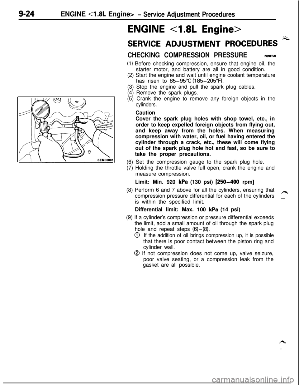
9-24ENGINE - Service Adjustment Procedures
ENGINE 4.8L Engine>
SERVICE ADJUSTMENT PROCEDURES -
CHECKING COMPRESSION PRESSURENOSFFAI
(1) Before checking compression, ensure that engine oil, the
starter motor, and battery are all in good condition.
(2) Start the engine and wait until engine coolant temperature
has risen to
85-95°C (185-205°F).
(3) Stop the engine and pull the spark plug cables.
(4) Remove the spark plugs.
(5) Crank the engine to remove any foreign objects in the
cylinders.Caution
Cover the spark plug holes with shop towel, etc., in
order to keep expelled foreign objects from flying out,
and keep away from the holes. When measuring
compression with water, oil, or fuel having entered the
cylinder through a crack, etc., these will come flying
out of the spark plug hole hot and fast, so be sure to
take the proper precautions.
(6) Set the compression gauge to the spark plug hole.
(7) Holding the throttle valve full open, crank the engine and
measure compression.
Limit: Min. 920
kPa (130 psi) [250-400 rpm]
(8) Perform 6 and 7 above for all the cylinders, ensuring that
compression pressure differential for each of the cylinders
/Iis within the specified limit.
__Differential limit: Max. 100
kPa (14 psi)
(9) If a cylinder’s compression or pressure differential exceeds
the limit, add a small amount of oil through the spark plug
hole and repeat steps (6)-(8).
0If the addition of oil brings compression up, it is possiblethat there is poor contact between the piston ring and
cylinder wall.
@ If not compression does not come up, valve seizure,
poor valve seating, or a compression leak from the
gasket are all possible.
/y
-