1991 MITSUBISHI ECLIPSE oil temperature
[x] Cancel search: oil temperaturePage 1163 of 1216

-.
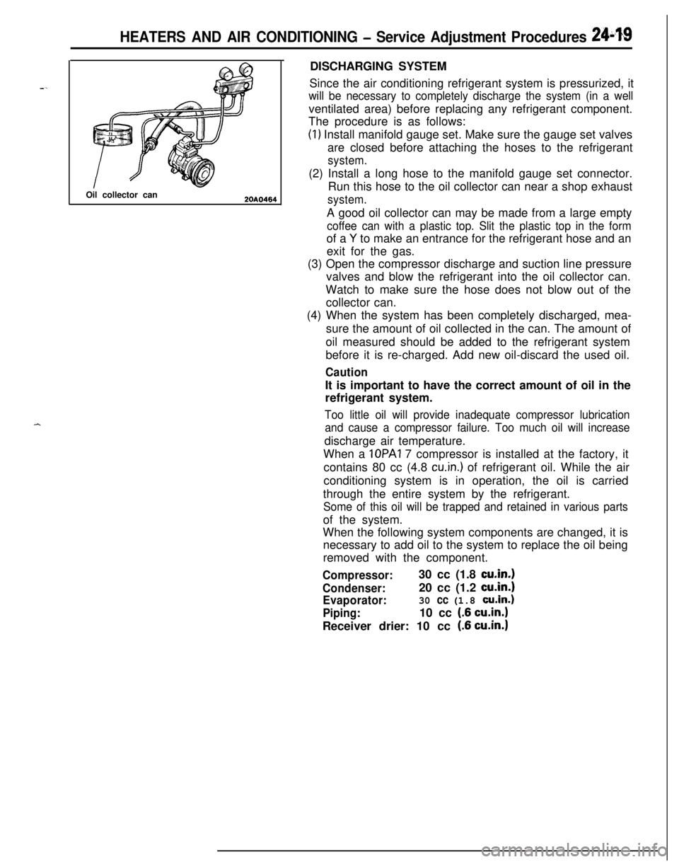
HEATERS AND AIR CONDITIONING - Service Adjustment Procedures 241$19Oil collector can
2OAO464DISCHARGING SYSTEM
Since the air conditioning refrigerant system is pressurized, it
will be necessary to completely discharge the system (in a wellventilated area) before replacing any refrigerant component.
The procedure is as follows:
(1) Install manifold gauge set. Make sure the gauge set valves
are closed before attaching the hoses to the refrigerant
system.(2) Install a long hose to the manifold gauge set connector.
Run this hose to the oil collector can near a shop exhaust
system.A good oil collector can may be made from a large empty
coffee can with a plastic top. Slit the plastic top in the formof a
Y to make an entrance for the refrigerant hose and an
exit for the gas.
(3) Open the compressor discharge and suction line pressure
valves and blow the refrigerant into the oil collector can.
Watch to make sure the hose does not blow out of the
collector can.
(4) When the system has been completely discharged, mea-
sure the amount of oil collected in the can. The amount of
oil measured should be added to the refrigerant system
before it is re-charged. Add new oil-discard the used oil.
CautionIt is important to have the correct amount of oil in the
refrigerant system.
Too little oil will provide inadequate compressor lubrication
and cause a compressor failure. Too much oil will increasedischarge air temperature.
When a IOPAI 7 compressor is installed at the factory, it
contains 80 cc (4.8
cu.in.) of refrigerant oil. While the air
conditioning system is in operation, the oil is carried
through the entire system by the refrigerant.
Some of this oil will be trapped and retained in various partsof the system.
When the following system components are changed, it is
necessary to add oil to the system to replace the oil being
removed with the component.
Compressor:30 cc (1.8 cu.in.1
Condenser:20 cc (1.2 cu.in.1
Evaporator:30 cc (1.8 cu.in.)
Piping:10 cc (.6 cu.in.1Receiver drier: 10 cc
(.6 cu.in.1
Page 1168 of 1216

24-24 HEATERS AND AIR CONDITIONING - Service Adjustment Procedures
COMPRESSOR NOISENUFIABWhen investigating an air conditioning related noise, you must
first know the conditions when the noise occurs. These
conditions are: weather, vehicle speed, in gear or neutral,
engine temperature or any other special conditions.
Noises that develop during air conditioning operation can oftenbe misleading. For example: what sounds like a failed front
bearing or connecting rod, may be caused by loose bolts, nuts,mounting brackets, or a loose clutch assembly. Verify acces-
sory drive belt tension (power steering, or alternator).
Improper accessory drive belt tension can cause a misleading
noise when the compressor is engaged and little or no noise
when the compressor is disengaged.
Drive belts are speed sensitive. That is, at different engine
speeds, and depending upon belt tension, belts can develop
unusual noises that are often mistaken for mechanical prob-
lems within the compressor.
Adjustment Procedures
(1) Select a quiet area for testing. Duplicate conditions as
much as possible. Switch compressor on and off several
times to clearly identify compressor noise.
To duplicate high ambient conditions (high head pressure),restrict air flow through condenser. Install manifold gauge
set to make sure discharge pressure doesn’t exceed 2,070
kPa (300 psi).
(2) Tighten all compressor mounting bolts, clutch mounting
bolt, and compressor drive belt. Check to assure clutch coilis tight (no rotation or wobble).
(3) Check refrigerant hoses for rubbing or interference that cancause unusual noises.
(4) Check refrigerant charge (See “Charging the System”).
(5) Recheck compressor noise as in Step 1.
(6) If noise still exists, loosen compressor mounting bolts and
retorque. Repeat Step 1.
(7) If noise continues, replace compressor and repeat Step 1.
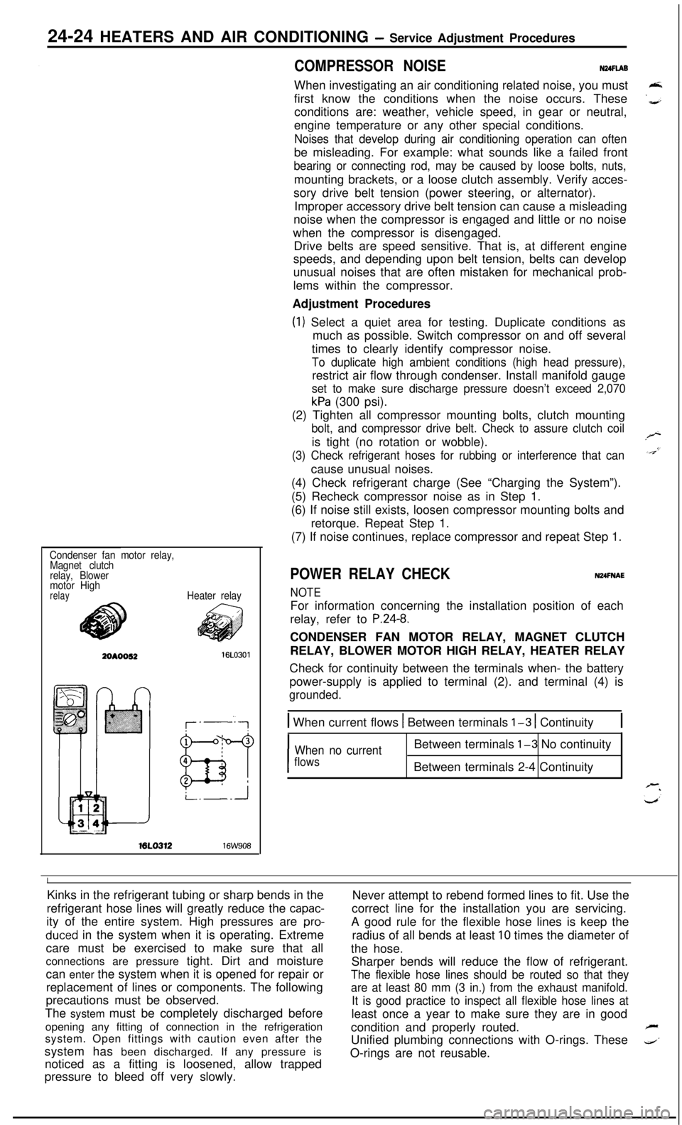
Condenser fan motor relay,
Magnet clutch
relay, Blower
motor High
relayHeater relayML0312
16W908
POWER RELAY CHECKNUFNAE
NOTEFor information concerning the installation position of each
relay, refer to
P.24-8.CONDENSER FAN MOTOR RELAY, MAGNET CLUTCH
RELAY, BLOWER MOTOR HIGH RELAY, HEATER RELAY
Check for continuity between the terminals when- the battery
power-supply is applied to terminal (2). and terminal (4) is
grounded.
1 When current flows 1 Between terminals l-3 1 Continuity1
I
When no currentBetween terminals l-3 No continuity
flowsBetween terminals 2-4 Continuity
IKinks in the refrigerant tubing or sharp bends in the
Never attempt to rebend formed lines to fit. Use the
refrigerant hose lines will greatly reduce the
capac-correct line for the installation you are servicing.
ity of the entire system. High pressures are
pro-A good rule for the flexible hose lines is keep the
duced in the system when it is operating. Extreme
radius of all bends at least 10 times the diameter of
care must be exercised to make sure that all
the hose.
connections are pressure tight. Dirt and moisture
Sharper bends will reduce the flow of refrigerant.
can enter the system when it is opened for repair or
The flexible hose lines should be routed so that theyreplacement of lines or components. The following
are at least 80 mm (3 in.) from the exhaust manifold.precautions must be observed.
It is good practice to inspect all flexible hose lines atThe system must be completely discharged before
least once a year to make sure they are in good
opening any fitting of connection in the refrigeration
condition and properly routed.
Fsystem. Open fittings with caution even after the
Unified plumbing connections with O-rings. These
4’system has been discharged. If any pressure is
noticed as a fitting is loosened, allow trappedO-rings are not reusable.
pressure to bleed off very slowly.
Page 1195 of 1216

HEATERS AND AIR CONDITIONING- Engine Coolant Temperature Switch24-51
ENGINE COOLANT TEMPERATURE SWITCH <2.0L DOHC Engine>
-.REMOVAL AND INSTALLATIONN24xA-
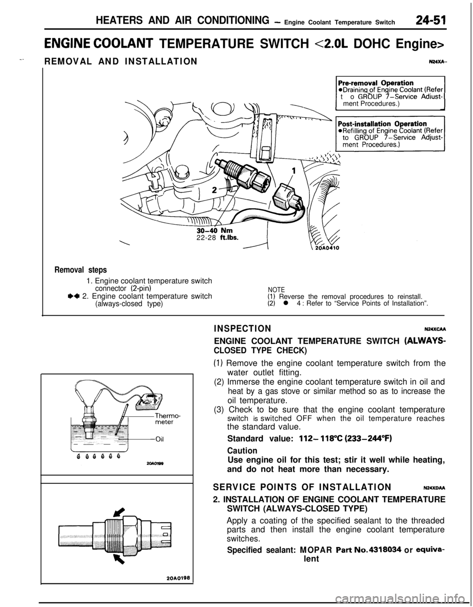
1 to GROUP f-service Adjust-1ment Procedures.)
22-28
ft.lbs.
Removal steps1. Engine coolant temperature switch
connector (2-pin)
.4 2. Engine coolant temperature switch(always-closed type)
NOTE(1) Reverse the removal procedures to reinstall.(2) l 4 : Refer to “Service Points of Installation”.
20A0190I
INSPECTIONN24XcAAENGINE COOLANT TEMPERATURE SWITCH
(ALWAYS-
CLOSED TYPE CHECK)
(1) Remove the engine coolant temperature switch from the
water outlet fitting.
(2) Immerse the engine coolant temperature switch in oil and
heat by a gas stove or similar method so as to increase theoil temperature.
(3) Check to be sure that the engine coolant temperature
switch is switched OFF when the oil temperature reaches
the standard value.
Standard value:
112- 118°C (233-244°F)
CautionUse engine oil for this test; stir it well while heating,
and do not heat more than necessary.
SERVICE POINTS OF INSTALLATIONN24XDM2. INSTALLATION OF ENGINE COOLANT TEMPERATURE
SWITCH (ALWAYS-CLOSED TYPE)
Apply a coating of the specified sealant to the threaded
parts and then install the engine coolant temperature
switches.
Specified sealant: MOPAR Part No.4318034 or ewiva-lent
Page 1198 of 1216

EMISSION CONTROL SYSTEMS - Specifications
SPECIFICATIONS
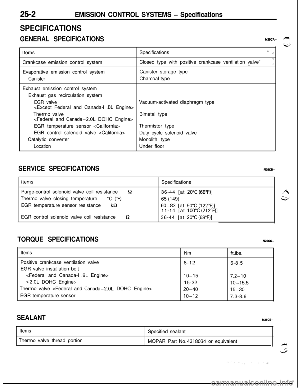
GENERAL SPECIFICATIONSN25CA-ItemsSpecifications
.,:..rCrankcase emission control systemClosed type with positive crankcase ventilation valve”I
‘:Evaporative emission control systemCanister storage type
CanisterCharcoal type
Exhaust emission control system
Exhaust gas recirculation system
EGR valveVacuum-activated diaphragm type
Therm0 valveBimetal type
EGR temperature sensor
EGR control solenoid valve
Duty cycle solenoid valve
Catalytic converterMonolith type
LocationUnder floor
SERVICE SPECIFICATIONSN25CB-
ItemsSpecifications
Purge-control solenoid valve coil resistance
&236-44 [at 20°C (68”F)I
Therm0 valve closing temperature“C (“F)65 (149)
EGR temperature sensor resistance
kQ60-83 [at 50°C (122”F)]11-14 [at
100°C (212”F)]EGR control solenoid valve coil resistance
S236-44 [at 20°C (68”F)]
TORQUE SPECIFICATIONSN25CC-
ItemsPositive crankcase ventilation valve
EGR valve installation bolt
<2.0L DOHC Engine>
Therm0 valve
EGR temperature sensor
Nmftlbs.8-12
6-8.5
IO-157.2-1015-22
10-15.5
20-4015-30
10-127.3-8.6
SEALANT
Items
Therm0 valve thread portionSpecified sealant
MOPAR Part No.4318034 or equivalent