1991 MITSUBISHI ECLIPSE clutch
[x] Cancel search: clutchPage 109 of 1216

REAR AXLE - Troubleshooting3-7
Symptom
NOTE
1 Probable cause1 Remedy
In addition to a malfunction of the differential carrier components, abnormal noise can also be caused by the universal
joint of the propeller shaft, the axle shafts, the wheel bearings, etc. Before disassembling any parts, take all
possibilities into consideration and confirm the source of the noise.
Abnormal noise when
Damaged differential gears
ReplacecorneringDamaged pinion shaftInsufficient gear oil quantity
Replenish
Gear noiseImproper final drive gear tooth contact adjustmentAdjust or replace
Incorrect final drive gear backlashAdjust
Improper drive pinion preload adjustment
Damaged, broken, and/or seized tooth surfaces of
Replacethe drive gear and drive pinion
Damaged, broken, and/or seized drive pinion bear-
ings
NOTE
Damaged, broken, and/or seized side bearings
Damaged differential case
Inferior gear oilInsufficient gear oil quantity
Replenish
Noise from the engine, muffler vibration, transaxle, propeller shaft, wheel bearings, tires, body, etc., is easily mistaken
as being caused by malfunctions in the differential carrier components. Be extremely careful and attentive whenperforming the driving test, etc.
Test methods to confirm the source of the abnormal noise include:coasting acceleration, constant speed driving,
raising the rear wheels on a jack, etc. Use the method most appropriate to the circumstances.
Gear oil leakageWorn or damaged front oil seal, or an improperlyReplace
installed oil seal
Damaged gasket
Seizure
VOTE
Loose companion flange self-locking nut
Loose filler or drain plug
Clogged or damaged vent plug
Insufficient final drive gear backlash
Excessive drive pinion preload
Excessive side bearing preload
Insufficient differential gear backlash
Excessive clutch plate preload
Inferior gear oilInsufficient gear oil quantityRetighten or replace
Retighten or apply adhesive
Clean or replaceAdjust
Replace
Replenish
n the event of seizure, disassemble and replace the parts involved, and also be sure to check all components for any
rregularities and repair or replace as necessary.
3reak downIncorrect final drive gear backlashAdjustInsufficient drive pinion preload
Insufficient side bearing preload
Excessive differential gear backlash
Loose drive gear clamping boltsRetighten
VOTEn addition to disassembling and replacing the failed parts, be sure to check all components for irregularities and repairIr
replace as necessary.
The limited slip differentialThe limited slip device is damagedDisassemble, check the func-
lees not function (ontioning, and replace the dam-
;now, mud, ice, etc.)aged parts
Page 144 of 1216

5-4BRAKES - Specifications
SERVICE SPECIFICATIONS
NO5CB-
ItemsSpecifications
Standard value
Brake pedal heightmm (in.) 176-181 (6.9-7.1)
Brake pedal free playmm (in.) 3-8
(l-.3)Brake pedal to floorboard clearance
mm (in.) 80 (3.1) or more
Parking brake lever stroke
5-7 notches
Output pressure proportioning valve
MPa (psi)
Split point
Output pressure [input pressure]
N (Ibs.) [Nm (ftlbs.)]70 (15) or less [4 (3) or less1Booster push rod to master cylinder piston clearance
mm (in.)
9 inch brake booster
0.8-l .O (.031-,039)
7
+8 inch brake booster0.5-0.7 (.020-.028)
Speed sensor’s internal resistance
kQ 0.8-l .2*
Clearance between the speed pole piece and
the toothed rotor
mm (in.)
0.3-0.9 (.012-,035)”Limit
Left/right proportioning valve out pressure difference
MPa (psi)0.4 (57)
Disc brake pad thickness
mm (in.) 2.0 (08)
Front disc thickness
mm (in.) 22.4 (882)
Rear disc thickness
mm (in.) 8.4
(.331)Disc
runoutmm (in.) 0.08 (.0031)Hub end play
mm (in.) 0.008
(.00031)
NOTE
*: Vehicles with ABS
TORQUE SPECIFICATIONS
ItemsNmft.lbs.
Pedal support bracket installation bolts
8-12
6-9
Pedal support bracket installation nut
IO-157-11
Pedal rod to pedal support bracket
17-26
12-19
Pedal rod to clutch pedal bracket
17-26
12-19
Clutch pedal bracket installation bolt
8-12
6-9
Turn-over spring mounting bolt
17-26
12-19
Stop lamp switch mounting nut
IO-157-l 1‘Clutch master cylinder installation nuts
10-157-11
Clutch pedal installation nut
20-2514-18
Lever assembly (A) installation nut
20-2514-18
Lever assembly
(B) installation nut20-2514-18
Page 194 of 1216

5-54BRAKES -Brake Pedal
IO-15 Nm
7-11 ft.lbs.
\
20-25 Nm
14-18 ft.lbs.I17-26 Nm
12-19 ft.lbs.
18-12 Nm
- 6-9 ft.lbs.- /-
117-11 ft.lbs.
13clutch switch Stop light switchconnectorStop light switch
Clutch switch connector andInter lock switch connector
Return springReturn spring
Clip
Turn over spring
Cotter pin
Washer
Clevis pin
1::16.
1::19.
22.
23.
W 25.
4*26.I)4 27.28.
Brake booster push rod
Pedal and bracket assembly
Clutch pedal mounting nut
Lever assembly
Clutch pedal bracketInter lock switch
Pedal support bracket
Clutch pedal
Bushing
P,;$;d
Brake pedal
14AG451
Fyfeverse the removal procedures to reinstall.
(2) 4* : Refer to “Service Points of Removal”.
(3) l 4 : Refer to “Service Points of Installation”.# m : Non-reusabje parts*: Vehicles with auto-cruise control system
SERVICE POINTS OF REMOVAL
NO5GBAHa
26. REMOVAL OF PEDAL RODUsing a plastic hammer, remove the pedal rod from the
pedal support bracket.
Page 195 of 1216

BRAKES - Brake Pedal5-55
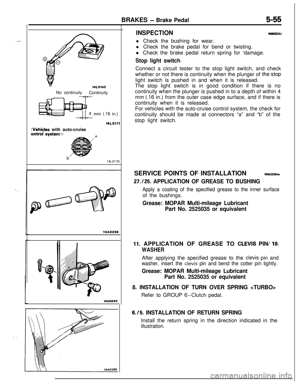
14L0142No continuity
Continuity
mm
t.16 in.)
14LO171
:Vehicles with auto-cruiseontrol svstem>
14A0256
14ll0050
INSPECTIONNoMicAll Check the bushing for wear.
l Check the brake pedal for bend or twisting.
l Check the brake pedal return spring for ‘damage.
Stop light switchConnect a circuit tester to the stop light switch, and check
whether or not there is continuity when the plunger of the’stop
light switch is pushed in and when it is released.
The stop light switch is in good condition if there is no
continuity when the plunger is pushed in to a depth of within 4
mm
(.I6 in.) from the outer case edge surface, and if there is
continuity when it is released.
For vehicles with the auto-cruise control system, the check for
continuity should be made at connectors “a” and “b” of the
stop light switch.
SERVICE POINTS OF INSTALLATIONN05GDBAa
27.125. APPLICATION OF GREASE TO BUSHING
Apply a coating of the specified grease to the inner surfaceof the bushings.
Grease: MOPAR Multi-mileage Lubricant
Part No. 2525035 or equivalent
11. APPLICATION OF GREASE TO CLEVIS PIN/ IO.
WASHERAfter applying the specified grease to the
clevis pin and
washer, insert the clevis pin and bend the cotter pin tightly.
Grease: MOPAR Multi-mileage Lubricant
Part No. 2525035 or equivalent
8. INSTALLATION OF TURN OVER SPRING
6-Clutch pedal.
6.15. INSTALLATION OF RETURN SPRINGInstall the return spring in the direction indicated in the
illustration.
Page 231 of 1216

6-I
CLUTCH
CONTENTS
CLUTCH CONTROL. . . . . . . . . . . . . . . . . . . . . . . . . . . . . . . . . . . . . . . . .9SPECIFICATIONS. . . . . . . . . . . . . . . . . . ..m........................2
GeneralSpecifications..................................2CLUTCH COVER AND DISC..........................16Lubricants......................................................3
CLUTCH MASTER CYLINDER........................11Service Specifications...................................2Torque Specifications
...................................3
CLUTCH PEDAL..............................................7
TROUBLESHOOTING. . . . . . . . . . . . . . . . . . . . . . . ..*............4
CLUTCHRELEASE CYLINDER . . . . . . . ..a.............13Clutch chatters
SERVICE ADJUSTMENT PROCEDURES . . . . . . .5Clutch noise
Bleeding. . . . . . . . . . . . . . . . . . . . . . . . . . . . . . . . . . . . . . . . . . . . . . . . . . . . . . . .6Clutch pedal feels “heavy”
Clutch Pedal Inspection and Adjustment . . . .
5Clutch slips
SPECIAL TOOL,.,#mmm,.*......B......................*........3Gear shift malfunctionCAUTIONWhen
servicing clutch assemblies or com-
ponents for vehicles with 1.8L engine, doNOT
create dust by sanding or by cleaning
clutch parts with a dry brush or with
compressed air. (A water dampened cloth
should be used). The clutch disc contains
“Asbestos Fibers” which can become air-
borne if dust is created during serviceoperations. Breathing dust containing
“Asbestos Fibers”may cause seriousbodily
harm.
Page 232 of 1216

6-2CLUTCH - SDecifications
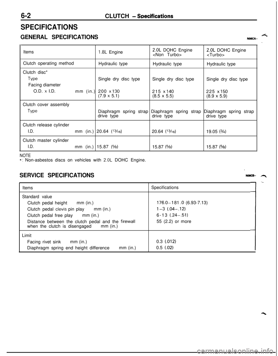
SPECIFICATIONS
GENERAL SPECIFICATIONS
Items1.8L Engine2.0L DOHC Engine
Clutch operating method
Hydraulic type
Hydraulic type
Hydraulic type
Clutch disc*
TypeSingle dry disc type
Single dry disc type
Single dry disc type
Facing diameter
O.D.
x I.D.
mm (in.) 200 x 130215 x 140225 x 150(7.9 x 5.1)
(8.5 x 5.5)
(8.9 x 5.9)
Clutch cover assembly
TypeDiaphragm spring strap Diaphragm spring strap Diaphragm spring strap
drive type
drive type
drive type
Clutch release cylinder
I.D.mm (in.) 20.64 (13/16)20.64 (13/6)19.05 (3h)Clutch master cylinder
I.D.mm (in.) 15.87 (%)15.87 (%)15.87 (543)
NOTE*: Non-asbestos discs on vehicles with 2.0L DOHC Engine.
SERVICE SPECIFICATIONS
Items
Standard valueClutch pedal heightmm (in.)
Clutch pedal
clevis pin playmm (in.)
Clutch pedal free playmm (in.)
Distance between the clutch pedal and the firewall
when the clutch is disengagedmm (in.)
Limit
Facing rivet sinkmm (in.)
Diaphragm spring end height differencemm (in.)
NO6lX- .H,
Specifications
176.0-I 81 .O (6.93-7.13)
l-3 (.04-.12)6-13 (.24-.51)
55 (2.2) or more
0.3 (012)
0.5
(.02)L-
Page 233 of 1216

CLUTCH - Specifications/Special Tool6-3
TORQUE SPECIFICATIONSNMCC-Items
Nmftlbs.Clutch pedal to clutch pedal support bracket
20-2514-18
Clutch pedal support bracket
8-12
6-9
Clutch pedal support bracket to firewall
10-157-l 1Stop light switch
10-157-11
Brake booster installation nut
11-17
8-12
Master cylinder to firewall
10-157-11
Pedal rod to clutch pedal support bracket
17-2612-19
Clutch pedal bracket
8-l 26-9
Pedal rod to clutch pedal bracket
17-2612-19
Clutch tube flare nut
13-17
9-12
Air cleaner bracket
8-12
6-9
Clutch tube clamp to body
8-l 26-9
Reservoir band
5-7
4-5
Clutch release cylinder
15-22
11-16Clutch release cylinder to union bolt
2518Bleeder plug
9-13
7-9
Fulcrum35-4225-30Clutch cover assembly
15-22
11-16
- LUBRICANTSNOSCD-Items
Contact surface of release bearing and fulcrum of clutch
release fork
Inner surface of clutch release bearing
Inner surface of clutch disc splineSpecified lubricants
MOPAR Multi-mileage Lubricant
Part
No.2525035 or equivalent
Contact portion of release fork to release cylinder push rod
Bushing,
clevis pin, washer and bushing
Inner surface of clutch release cylinder and outer
circumference of piston and cupMOPAR Brake Fluid/Conforming to
DOT3Inner surface of clutch master cylinder and outer
circumference of piston assembly
SPECIAL TOOL
ToolNumber
MD9981 26
NameUse
Clutch disc center
guideClutch disc center hole alignment
\\
Page 234 of 1216

6-4CLUTCH - Troubleshooting
TROUBLESHOOTINGNO6hi.J
SymptomProbable causeRemedy
Clutch slipsInsufficient clutch pedal playAdjust
Excessive wear of clutch disc facingReplace
Hardening of clutch disc facing, or adhesion of oilReplace
Clutch release fork catchingRepair or replace parts
Weak or damaged diaphragm spring
Replace
Clogging of hydraulic systemRepair or replace parts
Gear shift malfunctionExcessive clutch pedal playAdjust
Distorted clutch disc, excessive oscillation
Replace
Clutch cover assembly wornReplace
Clutch disc spline worn or corrodedReplace
Clutch disc facing peelingReplace
Clutch release bearing wornReplace
Damaged pressure plate or flywheelReplace
Leakage, air introduction or clogging of hydraulic systemRepair or replace parts
Clutch noiseInsufficient clutch pedal playAdjust
Improper installation of clutch cover assemblyRepair or replace parts
Excessive wear of clutch disc facing
Replace
Clutch release fork catchingRepair or replace parts
Clutch release bearing worn
Replace
Weak or damaged torsion springReplace
Damaged pilot bushingReplace
Insufficient lubrication of bearing sleeve sliding surfaceRepairClutch pedal feels “heavy”
Insufficient lubrication of clutch pedalRepairInsufficient lubrication of clutch disc spline
Repair
Clutch release fork catchingRepair or replace parts
Insufficient lubrication of bearing sleeve sliding surface
Repair
Clutch chattersWorn or damaged clutch disc facingReplace
Oil adhered to clutch disc facingReplace
Uneven height of diaphragm springRepair or replace parts
Weak or damaged torsion spring
Replace
Damaged pressure plate or flywheelReplace
Loose or damaged mountingReplace or tighten
mounting