1991 MITSUBISHI ECLIPSE brake
[x] Cancel search: brakePage 245 of 1216

.-CLUTCH - Clutch Release Cvlinder6-15
\
Piston
@*
CUP6CLOOO3DCLOOE
,
INSPECTIONNWLCAV(1) Check the inner surface of the release cylinder for
scratches or irregular wear.
(2) Replace if the piston cup outer circumference is scratched
or shows signs of fatigue, or if there is excessive wear of
the lip where indicated in the figure.
SERVICE POINTS OF REASSEMBLYNO6LDAB
5. APPLICATION OF FLUID TO PISTON AND CUP
Apply specified brake fluid to the release cylinder inside andouter surface of the piston and piston cup and push the
piston cup assembly in the cylinder.
Specified brake fluid: MOPAR Brake Fluid/Conforming
to DOT3
Page 315 of 1216
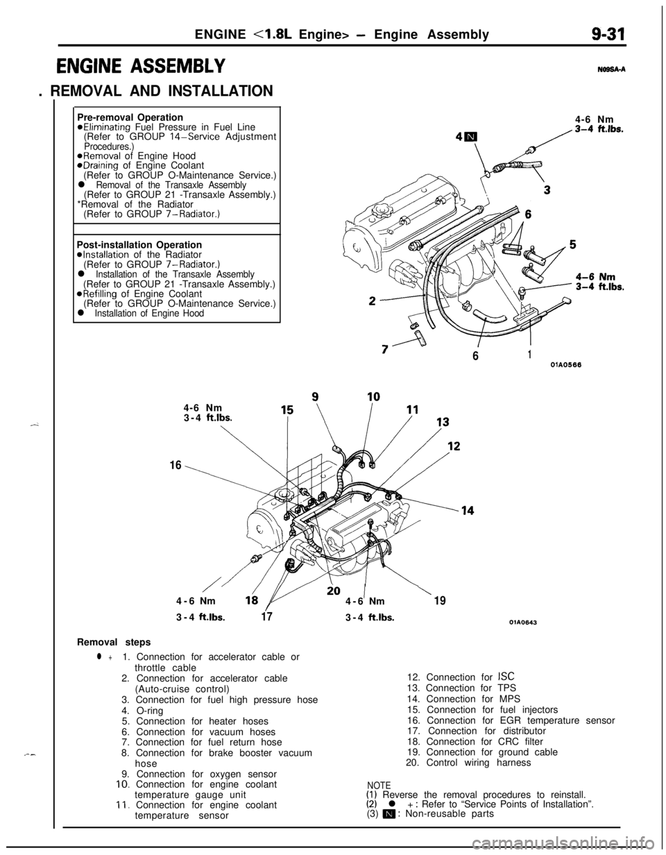
ENGINE <1.8L Engine> - Engine Assembly9-31
ENGINE ASSEMBLY
. REMOVAL AND INSTALLATION
N69SA-APre-removal Operation
@Eliminating Fuel Pressure in Fuel Line
(Refer to GROUP 14-Service AdjustmentProcedures.)@Removal of Engine HoodeDraining of Engine Coolant
(Refer to GROUP O-Maintenance Service.)
l Removal of the Transaxle Assembly(Refer to GROUP 21 -Transaxle Assembly.)
*Removal of the Radiator
(Refer to GROUP 7-Radiator.)
Post-installation Operation
@Installation of the Radiator
(Refer to GROUP 7-Radiator.)
l Installation of the Transaxle Assembly(Refer to GROUP 21 -Transaxle Assembly.)
@Refilling of Engine Coolant
(Refer to GROUP O-Maintenance Service.)
l Installation of Engine Hood4-6 Nm
“7
/61OlA05664-6 Nm
3-4
ft.lbs.
\
16
/io1\4-6Nm164-6Nm193-4ft.lbs.
173-4ft.lbs.OlA0643Removal steps
l +1. Connection for accelerator cable or
throttle cable
2. Connection for accelerator cable
(Auto-cruise control)
3. Connection for fuel high pressure hose
4. O-ring
5. Connection for heater hoses
6. Connection for vacuum hoses
7. Connection for fuel return hose
8. Connection for brake booster vacuum
hose
9. Connection for oxygen sensor
10. Connection for engine coolant
temperature gauge unit
11. Connection for engine coolant
temperature sensor12. Connection for
ISC13. Connection for TPS
14. Connection for MPS
15. Connection for fuel injectors
16. Connection for EGR temperature sensor
17. Connection for distributor
18. Connection for CRC filter
19. Connection for ground cable
20. Control wiring harness
NOTE(1) Reverse the removal procedures to reinstall.(2) l + : Refer to “Service Points of Installation”.
(3) m : Non-reusable parts
Page 320 of 1216
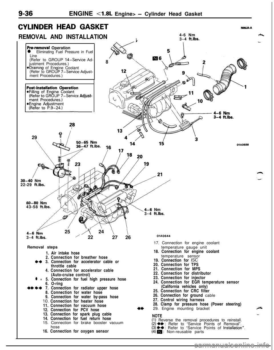
9-36ENGINE
CYLINDER HEAD GASKET
REMOVAL AND INSTALLATION4-6 Nm
73-4 ft.lbs.
NWJA-A
Pre-removal Operationl Eliminating Fuel Pressure in Fuel
Line(Refer to GROUP
14-Service Ad-
justment Procedures.)*Draining of En
ine Coolant
(Refer to GRO9P -/-Service Adjust-ment Procedures.)
(Refer to GROUP
7-Service Adjust-~~~~~~~n
?*
29?i
8
30-46 Nm
22-29 ft.lbs.
60-80 ium43-58 ftlbs.25
iy 24 \\3-4
ftlbs./2227 26
Removal steps
1. Air intake hose
2. Connection for breather hose
I)43. Connection for accelerator cable or
throttle cable
4. Connection for accelerator cable
(Auto-cruise control)
l +5. Connection for fuel high pressure hose
6. O-ring
+e W7. Connection for radiator upper hose
8. Connection for water hose
9. Connection for water by-pass hose
10. Connection for heater hose
11. Connection for vacuum hose
12. Connection for PCV hose
13. Connection for spark plug cable
14. Connection for fuel return hose
15. Connection for brake booster vacuum
hose
16. Connection for oxygen sensor
1\4-6 Nm
3-4 ftlbs.
OlAO556
QlAO64417. Connection for engine coolant
temperature gauge unit
18. Connection for engine coolant
temperature sensor
19. Connection for
ISC20. Connection for TPS
21. Connection for MPS
22. Connection for distributor
23. Connection for injector
24. Connection for EGR temperature sensor
(California vehicles only)
25. Connection for CRC filter
26. Connection for ground cable
27. Control wiring harness
28. Clamp for pressure hose (Power steering)
29. Engine mounting bracket
NOTE
(I) Reverse the removal procedures to reinstall.(2) Ce : Refer to “Service Points of Removal”.(3) ++ : Refer to “Service Points of Installation”.(4) m : Non-reusable parts
Page 365 of 1216
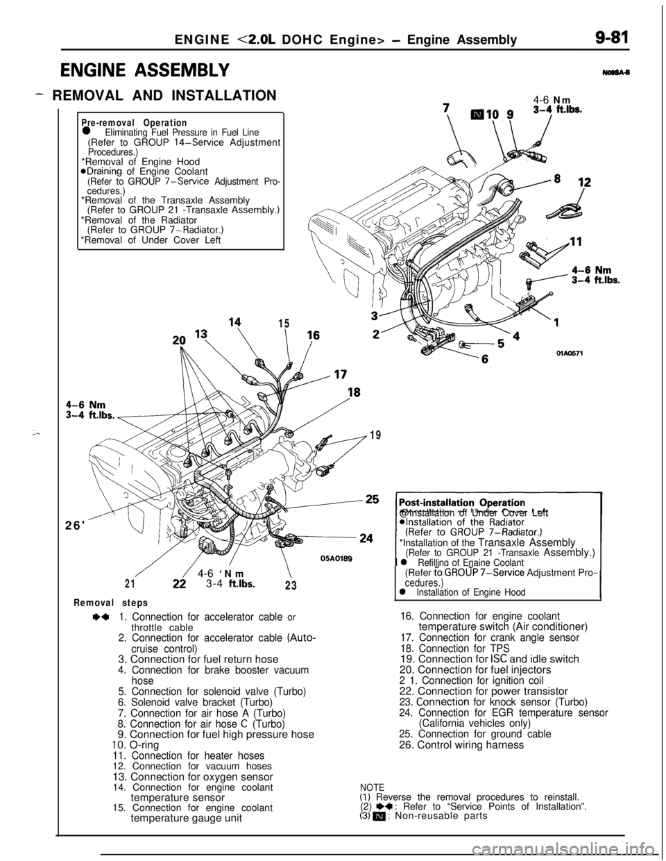
ENGINE <2.0L DOHC Engine> - Engine Assembly
ENGINE ASSEMBLY
- REMOVAL AND INSTALLATION
;-
Pre-removal Operationl Eliminating Fuel Pressure in Fuel Line(Refer to GROUP 14-Service AdjustmentProcedures.)*Removal of Engine Hood
@Draining of Engine Coolant(Refer to GROUP 7-Service Adjustment Pro-
cedures.)*Removal of the Transaxle Assembly
(Refer to GROUP 21 -Transaxle Assembly.)
*Removal of the Radiator
(Refer to GROUP 7-Radiator.)
*Removal of Under Cover Left
26'
15
I4-6 Nm\I /MAO571
19@Installation of Under Cover Left
*Installation of the Transaxle Assembly
(Refer to GROUP 21 -Transaxle Assembly.)
I l Refilling of Enaine Coolant
/22/ 4-6 ‘Nm\213-4 ftlbs.23
Removal steps
~~1. Connection for accelerator cable orthrottle cable
2. Connection for accelerator cable (Auto-
cruise control)3. Connection for fuel return hose
4. Connection for brake booster vacuum
hose
5. Connection for solenoid valve (Turbo)
6. Solenoid valve bracket (Turbo)
7. Connection for air hose A (Turbo)
8. Connection for air hose
C (Turbo)9. Connection for fuel high pressure hose
10. O-ring11. Connection for heater hoses12. Connection for vacuum hoses
13. Connection for oxygen sensor
14. Connection for engine coolant
temperature sensor
15. Connection for engine coolant
temperature gauge unit(Refer
t’o GROUP 7-Service Adjustment Pro-cedures.)l Installation of Engine Hood‘I
16. Connection for engine coolanttemperature switch (Air conditioner)
17. Connection for crank angle sensor
18. Connection for TPS19. Connection for
ISC and idle switch
20. Connection for fuel injectors
2 1. Connection for ignition coil22. Connection for power transistor
23. Connection for knock sensor (Turbo)
24. Connection for EGR temperature sensor
(California vehicles only)
25. Connection for ground cable26. Control wiring harness
NOTE(I) Reverse the removal procedures to reinstall.
(2) e+ : Refer to “Service Points of Installation”.(3) m : Non-reusable parts
Page 374 of 1216

9-90ENGINE <2.0L DOHC Engine> - Cylinder Head Gasket
CYLINDER HEAD GASKETNOSJA-S2.5-3.5 Nm 19
3 4 K
REIVIOVAL AND INSTALLATION2-3 ft.lbs.\ I i-6
Pre-removal Operation*Eliminating Fuel Pressure in Fuel20Line1\(Refer to GROUP 14-Service Ad-justment Procedures.)eDraining of Engine Coolant(Refer to GROUP 7-Service Adjust-
ment Procedures.)
,,vs4-6 Nm
’
II28
2936’
/w,=
3i38OlAO5.69
Removal stepsl
1. Connection for accelerator cable orthrottle cable
2. Connection for accelerator cable (Auto-
cruise control)3. Connection for oxygen sensor
temperature sensor
5. Connection for engine coolant
temperature gauge unit6. Connection for engine coolant
7. Connection for crank angle sensor
8. Connection for TPS
ISC and idle switch
10. Connection for fuel injector
12. Connection for power transistor
13. Connection for knock sensor (Turbo)
14. Connection for EGR temperature sensor
(California vehicles only)
15. Connection for ground cable
+e l + 17. Connection for radiator upper hose
/\05ADl9019. Center cover
20. Connection for spark plug cable assembly
21. Connection for air intake hose (Turbo)
22. Connection for breather hose (Turbo)
23.Airintakehose24. Connection for breather hose+e l 25. Connection for fuel high pressure hose26. O-ring
27. Connection for vacuum hoses
28. Connection for heater hose
29. Connection for water by-pass hose
30. Connection for PCV hose
31. Connection for vacuum hose (Turbo)
32. Connection for water hose (Turbo)
33. Eye-bolt (Turbo)
34. Gasket (Turbo)
35. Connection for oil pipe (Turbo)
36. Connection for vacuum hoses (Turbo)
37. Connection for fuel return hose
38. Connection for brake booster vacuum
hoseA
NOTE(1) Reverse the removal procedures to reinstall.(2) +I) : Refer to “Service Points of Removal”.
(3) ~~ : Refer to “Service Points of Installation”.
(4) m : Non-reusable parts
Page 435 of 1216
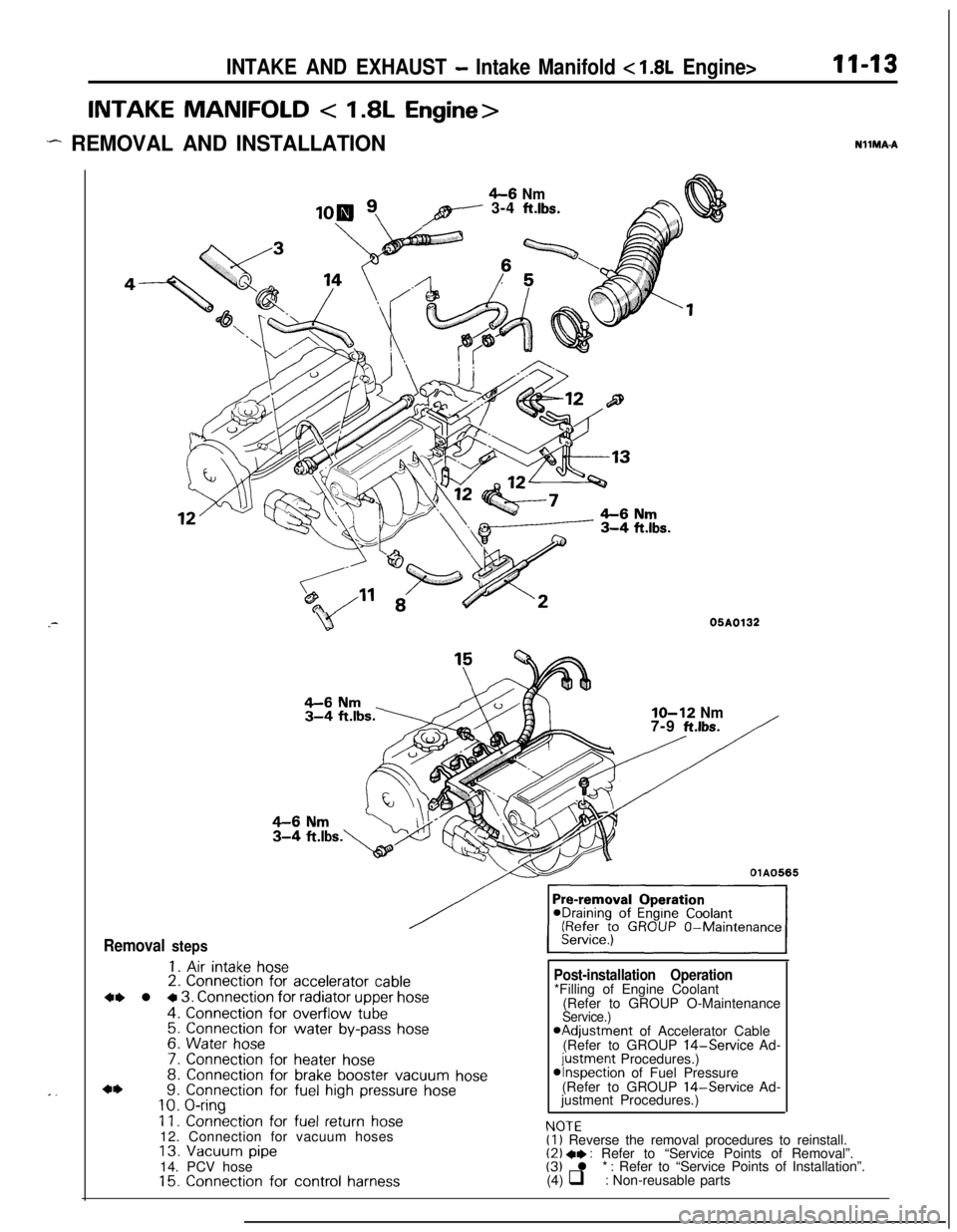
INTAKE AND EXHAUST - Intake Manifold < 1.8L Engine>
INTAKE MANIFOLD < 1.8L Engine>
.- REMOVAL AND INSTALLATION
11-13NllMA-A.-
. .
4-6 Nmpy---- 3-4 ft.lbs.
B05A0132
Removal steps
1. Air intake hose2. Connection for accelerator cable
4, l + 3. Connection for radiator upper hose
4. Connection for overflow tube5. Connection for water by-pass hose6. Water hose
7. Connection for heater hose8. Connection for brake booster vacuum hose9. Connection for fuel high pressure hose10. O-ring
11. Connection for fuel return hose12. Connection for vacuum hoses
13. Vacuum pipe14. PCV hose
15. Connection for control harness
IO-12 Nm7-9 ft.lbs.
OlA0565
Post-installation Operation
NfJTF*Filling of Engine Coolant
(Refer to GROUP O-Maintenance
Service.)aAdjustment of Accelerator Cable
(Refer to GROUP 14-Service Ad-
justment Procedures.)*Inspection of Fuel Pressure
(Refer to GROUP 14-Service Ad-
justment Procedures.)
I.” IL(1) Reverse the removal procedures to reinstall.(2) +* : Refer to “Service Points of Removal”.(3) l * : Refer to “Service Points of Installation”.
(4) q : Non-reusable parts
Page 439 of 1216
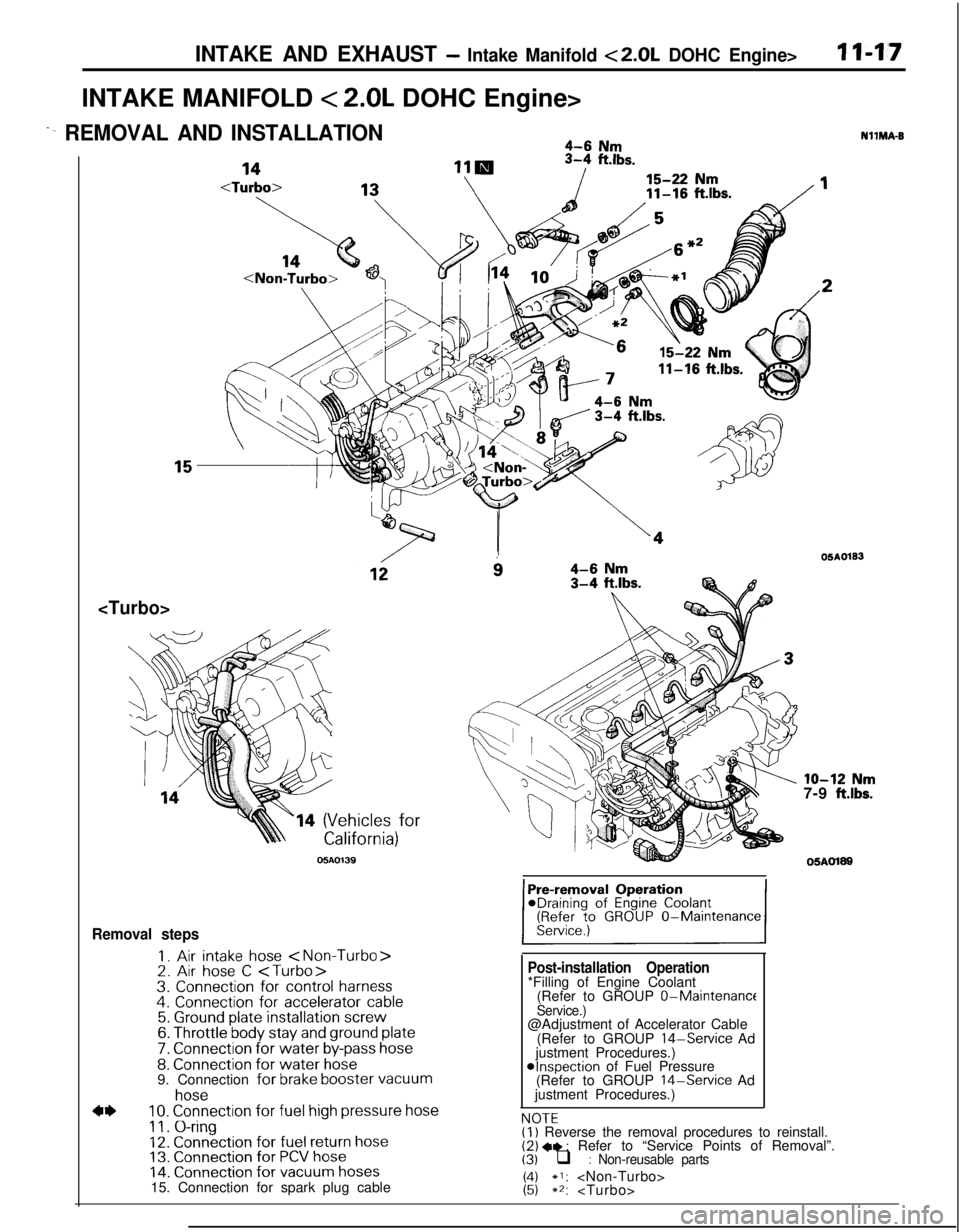
INTAKE AND EXHAUST - Intake Manifold <2.0L DOHC Engine>I I-1.7INTAKE MANIFOLD
< 2.0L DOHC Engine>
^- REMOVAL AND INSTALLATION4-6 Nm
ft.lbs.
14 (Vehicles for
05AO139
i34-6 Nm3-4 ftlbs.
Removal steps
I. Air intake hose
7. Connection for water by-pass hose8. Connection for water hose9. Connection for brake booster vacuum
4*
hose10. Connection for fuel high pressure hose
11. O-ring12. Connection for fuel return hose13. Connection for PCV hose14. Connection for vacuum hoses15. Connection for spark plug cable
Post-installation Operation*Filling of Engine Coolant
(Refer to GROUP 0-Maintenance
Service.)@Adjustment of Accelerator Cable
(Refer to GROUP
14-Service Ad
justment Procedures.)
@Inspection of Fuel Pressure
(Refer to GROUP 14-Service Ad
justment Procedures.)
NOTFNllMA-B
OSAO133
lo-12 Nm7-9 ft.lbs.
05AOl89
,.-.-(I) Reverse the removal procedures to reinstall.(2) +e : Refer to “Service Points of Removal”.(3) q : Non-reusable parts
1:;*I:
Page 565 of 1216

AUTO-CRUISE CONTROL SYSTEM - Troubleshooting144w
Auto-cruise control system cannot be set.
NOTEThis chart is to be used, then, for troubleshooting if it is not
possible to use the self-diagnosis for checking.
Prepare to conduct input check.
)( (Refer to P.14lrWhere codes
No.21, 22, 23, 25 and 26disolaved when, with the vehicle stationary,the’ input check codes were recalled?
‘#
No-8
cArc-3 ttie results of all inout checks normals?
L--y--
I
Check resultsProbable causeRemedy
ii”,:” chart
Code 21 remains even though SETSET switch ON mal-Replace the controlNo.2switch
is set to OFF.functionswitch
SET switch input lineRepair the harnessshort-circuit
:-Code 22 remains even though RE-SUME switch is set to OFF.RESUME switch ONmalfunction
RESUME switch input
line short-circuit
Replace the controlswitch
Repair the harnessNo.3
Code 23 is not canceled even if theMalfunction of stopReplace stop lightNo.6stop light switch
is turned OFF bylight switch circuit.switch or repair har-
releasing the brake pedal.ness.
Code 25 does not disappear, andMalfunction of theCheck or repair theNo.4
code 24 does not appear, evenvehicle-speed sensorvehicle speed sensor
though vehicle speed reaches appro-circuit (damaged or dis-circuit.ximately
40 km/h (25 mph) or higher.connected wiring, orshort-circuit)
Code 26 is not canceled even if theclutch switch is turned OFF by re-leasing the clutch pedal.Malfunction of clutch
switch circuit.
Replace clutch switchNo.8or repair harness.
Code 26 is not canceled even if theMalfunction of inhibitorReplace inhibitor switchNo. 7select lever is moved to anything butswitch circuit.or repair harness.
N, P
the auto-cruise vacuum pump circuit.NOTE_. . . e_,1 (Go to check chart No.5.)IIf the results of the check oT tne auro-crutse vacuum pump
circuit (check chart No. 5) and of the auto-cruise vacuum pump
and actuator itself (P.14-138.) reveal no abnormal
condition,replace
the electronic control unit (ECU).
-.