Page 981 of 1216
AUTOMATIC TRANSAXLE - Transaxle Assembly 21 b287
:\bearing #8 177006629. Assemble the forward sun gear, thrust race
#9, thrust
bearing
#8 and reverse sun gear.
30. Install the two sun gears assembled in the previous step inthe planetary carrier.
31. Install the reaction plate, brake disc and brake plate.
Caution
When using a new brake disc, first soak it for over 2
hours in ATF.
32. Install the pressure plate used during disassembly and theninstall the return spring.
Caution
Be sure to install the return spring in the correct
direction.
33. Apply a coating of petrolatum to the waved spring and
attach it to the center support.
Page 982 of 1216
21-288 AUTOMATIC TRANSAXLE - Transaxle Assemblv 34. Install the special tool on the center support, install new
O-rings (2 locations) pressing them into the transaxle case.Cautiona1. Apply ATF to the O-ring and align the oil hole.
L2. Install so the waved spring is aligned.
35. Install the snap ring.
36. Measure the end play of the low reverse brake with a
thickness gauge and select and adjust the pressure plate soit is within the standard value.
Standard value:
l.O- 1.2 mm (.039-.047 in.)v37. Install the air exhaust plug and then install the plug.
Air exhaust plug:
30-35 Nm (22-25 ft.lbs.)38. Install the anchor rod.
‘I
Page 992 of 1216

21-298 AUTOMATIC TRANSAXLE - Transaxle Assembly 91. Insert the center shaft and hit it with a plastic hammer or
similar instrument to install it securely
.
NOTEApply ATF to the oil seal lip and do not scratch it.
92. Apply ATF to the oil pump drive hub, install the torque
converter and push it in securely so dimension A shown in
the figure reaches the standard value.
Standard value: Approximately 16.3 mm
(.642 in.)
CAUTIONS DURING COMPONENT DISASSEM-
BLY AND REASSEMBLYGeneral cautions when cleaning
1. Clean each part, blow out oil passages and oil holes, etc.
with air and check that nothing is clogged.
2. For cleaning fluid, use the designated ATF (automatic
transmission fluid) or kerosene.3. When drying parts with air, be careful not to get ATF or
kerosene on your face.Cautions when handling parts
1. After washing the parts, arrange them in order so inspec-
tion, repairs and assembly can be performed properly.
2. When disassembling the valve body, store each valve,
making a group of the various springs.
3.Soak the new brake and clutch discs used for replacementin ATF for more than 2 hours before assembly.
General cautions during reassembly
1.Be sure to apply ATF to seal rings, clutch disc, clutch plateand rotating parts and sliding parts and then install.
2.Replace all gaskets and O-ring with new ones and do not
reuse the old ones.
3.Use petrolatum to hold the parts in their specified places.
Page 1017 of 1216
AUTOMATIC TRANSAXLE - Low-Reverse Brake21-323
LOW-REVERSE BRAKE
N21LSAA
c-
TFA0386
1. Low-reverse brake piston
2. D-ring
3. D-ring
4. Center support
!yTEeverse the disassembly procedures to reassemble.(2) q : Non-reusable parts
Page 1182 of 1216

24-38HEATERS AND AIR CONDITIONING - Compressor
2OAOO87
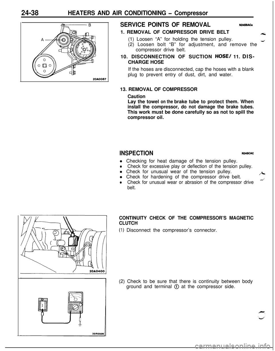
SERVICE POINTS OF REMOVALN248BACa1. REMOVAL OF COMPRESSOR DRIVE BELT
A;i(1) Loosen “A” for holding the tension pulley.
(2) Loosen bolt “B” for adjustment, and remove the
4compressor drive belt.
10. DISCONNECTION OF SUCTION
HOSE/ 11. DIS-
CHARGE HOSE
If the hoses are disconnected, cap the hoses with a blank
plug to prevent entry of dust, dirt, and water.
13. REMOVAL OF COMPRESSOR
Caution
Lay the towel on the brake tube to protect them. When
install the compressor, do not damage the brake tubes.This work must be done carefully so as not to spill the
compressor oil.
INSPECTIONN248CACl Checking for heat damage of the tension pulley.
lCheck for excessive play or deflection of the tension pulley.l Check for unusual wear of the tension pulley.
l Check for hardening of the compressor drive belt.
/J+-
lCheck for unusual wear or abrasion of the compressor drive&’
belt.
CONTINUITY CHECK OF THE COMPRESSOR’S MAGNETIC
CLUTCH
(1) Disconnect the compressor’s connector.
(2) Check to be sure that there is continuity between body
ground and terminal
@ at the compressor side.