1991 MITSUBISHI ECLIPSE specifications
[x] Cancel search: specificationsPage 1046 of 1216

23-2
SPECIFICATIONS
GENERAL SPECIFICATIONS
BODY - Specifications
N23CA--
Items
Hood
We
Door
Construction
Regulator system
Locking system
Liftgate
We
Slass installation method
Windshield glass
Quarter window glass
Liftgate window glass
Zlass thicknessmm (in.)
Windshield glass
Liftgate window glass
Door glass
Quarter window glass
‘ower window motor
Type
Revolutions under no loadwm
Revolutions under load
wmAt 1
Nm t.72 ft.lbs.1At 2
Nm (1.45 ft.lbs.1Bound current A
Direction of rotation
‘ower window main switch
Type
Rated load currentA
Lock switch
Power window switch
‘ower window sub switch
TvwRated load current A
‘ower window relay
Maximum contact currentA
Rated coil currentA
Voltage drop between terminalsV(At 12 V and the rated load current)
Specifications
Rear hinged, front opening type
Front-hinged, sash construction
Wire type
Pin-fork type
Inner-hinged, with gas damper
Adhesive type
Adhesive type
Adhesive type5.3
i.21)3.5
t.1413.5
t.1413.5
t.141
Permanent magnet type (Built-in circuit breaker)
75 or more65-95
50-80
34 or less
Clockwise and counter-clockwise
Automatic reset type
10
10
Automatic reset type
10
20
Max. 0.2
0.2 or less
Page 1047 of 1216
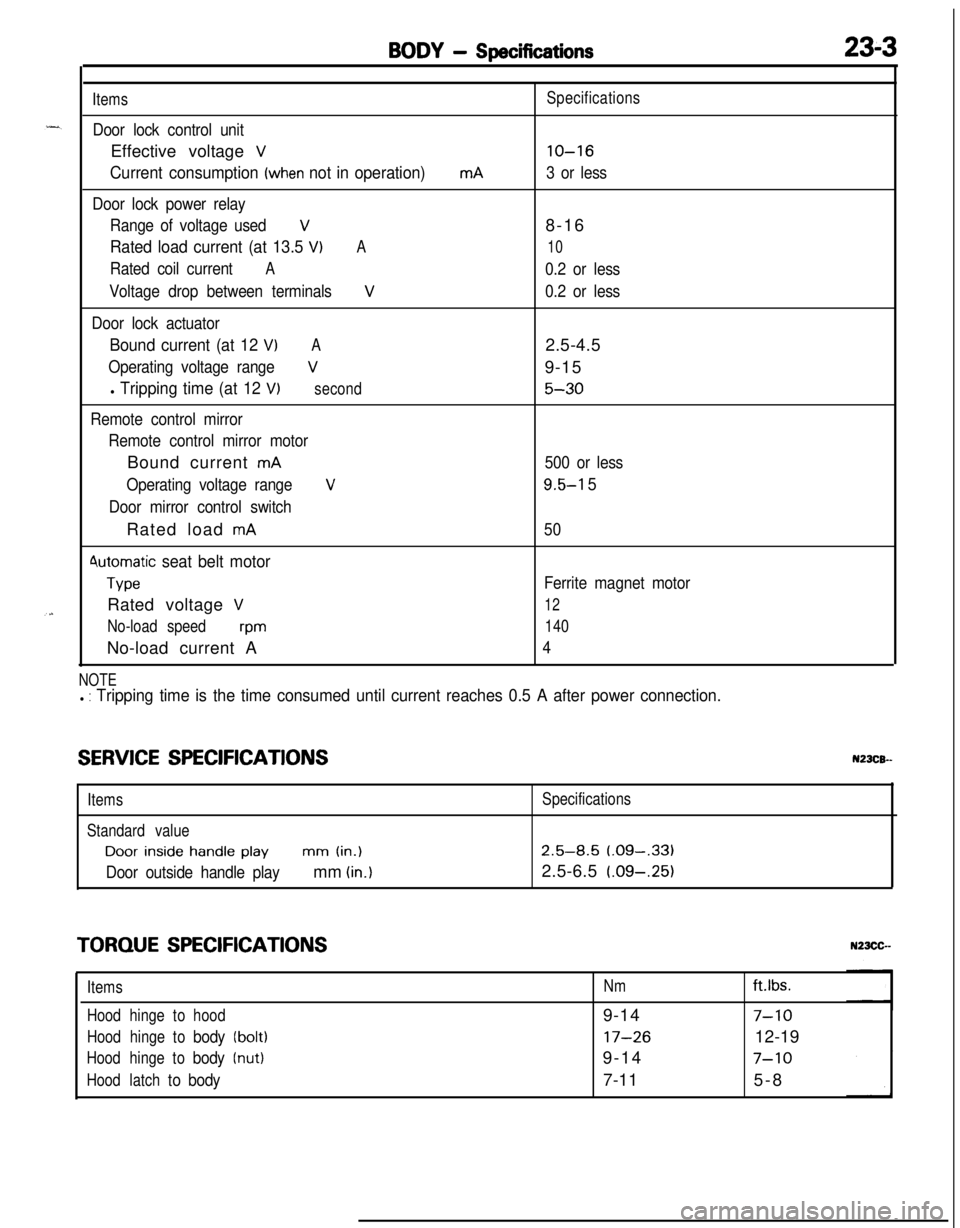
BODY - Specifications23-3
Items
Door lock control unitEffective voltage
V
Current consumption (when not in operation)
Door lock power relay
Range of voltage used
V
Rated load current (at 13.5 VIA
Rated coil currentA
Voltage drop between terminalsV
Door lock actuator
Bound current (at 12 VIA
Operating voltage rangeV
l Tripping time (at 12 V)second
Remote control mirror
Remote control mirror motorBound current
mA
Operating voltage range
V
Door mirror control switchRated load
mA
4utomatic seat belt motor
TypeRated voltage
V
No-load speedwmNo-load current A
mASpecifications
lo-16
3 or less8-16
10
0.2 or less
0.2 or less2.5-4.5
9-15
5-30
500 or less
9.5-l 5
50
Ferrite magnet motor
12
140
4
NOTEl : Tripping time is the time consumed until current reaches 0.5 A after power connection.
SERVICE SPECIFICATIONSN23CB--
ItemsSpecifications
Standard valueDoor
inside handle playmm (in.)2.5-8.5 (.09-,331
Door outside handle playmm (in.)2.5-6.5 (.09-.25)
TORQUE SPECIFICATIONS
ItemsNmft.lbs.
Hoodhingetohood9-14
7-10
Hoodhingetobody(bolt)17-2612-19
Hoodhingetobody(nut)9-147-10
Hoodlatchtobody7-115-8
Page 1049 of 1216
BODY - Specifications/Special Tools23-5
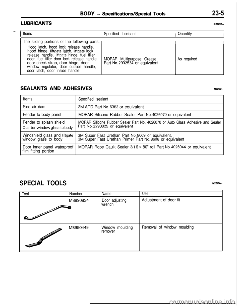
LUBRICANTSNZXD-
.^
IItemsSpecified lubricantIQuantityI
IThe sliding portions of the following parts:III
Hood latch, hood lock release handle,
hood hinge, liftgate latch, liftgate lock
release handle, liftgate hinge, fuel filler
door, fuel filler door lock release handle,
door check strap, door hinge, doorwindow regulator, door outside handle,
door latch, door inside handle
SEALANTS AND ADHESIVES
MOPAR Multipurpose Grease
Part No.2932524 or equivalent
As required
ItemsSpecified sealant
Side air dam
3M ATD Part No.6383 or equivalent
Fender to body panel
MOPAR Silicone Rubber Sealer Part No.4026070 or equivalent
Fender to splash shield
MOPAR Silicone Rubber Sealer Part No. 4026070 or Auto Glass Adhesive and Sealer
Quarter window glass to bodyh-t No.2298825 Or equivalent
Windshield glass and liftgate3M Super Fast Urethan Part No.8609 or equivalent,
window glass to body3M Super Fast Urethan Primer Part No.8608 or equivalent
Door inner panel waterproofMOPAR Rope Caulk Sealer
3/l 6 x 80” roll Part No.4026044 or equivalent
film fitting portion
SPECIAL TOOLS
ToolNumber
MB990834
Name
Door adjusting
wrench
Use
Adjustment of door fit
MB990449Window moulding
removerRemoval of window moulding
Page 1145 of 1216
24-l
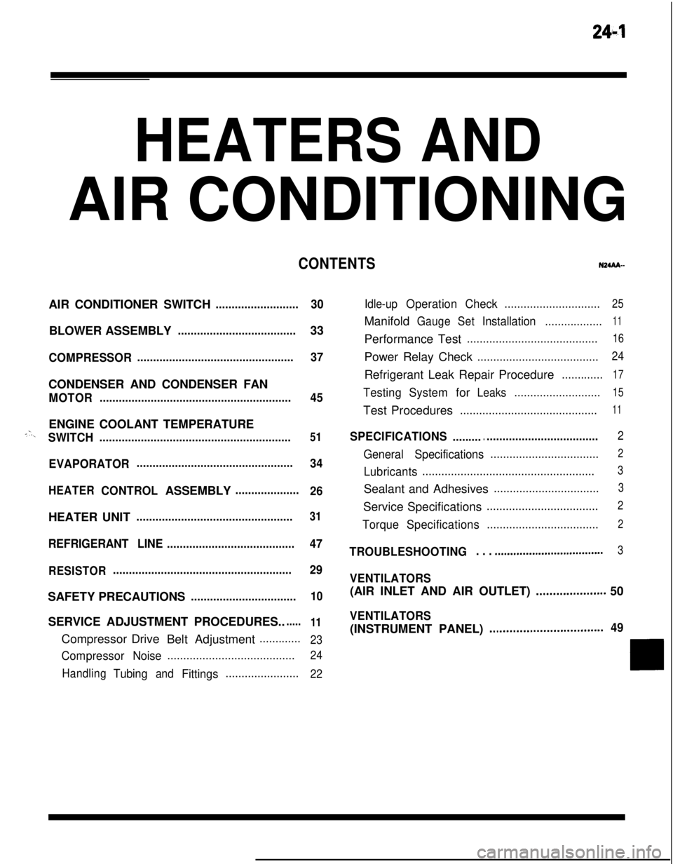
HEATERS ANDAIR CONDITIONING
CONTENTSN24M--AIR CONDITIONER SWITCH
..........................30BLOWER ASSEMBLY
.....................................33
COMPRESSOR.................................................37CONDENSER AND CONDENSER FAN
MOTOR............................................................45ENGINE COOLANT TEMPERATURE
-‘-.,SWITCH............................................................51
EVAPORATOR.................................................
34
HEATERCONTROLASSEMBLY....................
26HEATER UNIT
.................................................31
REFRIGERANTLINE........................................47
RESISTOR........................................................29SAFETY PRECAUTIONS
.................................10SERVICE ADJUSTMENT PROCEDURES..
.....11Compressor Drive
Belt Adjustment
.............
23
CompressorNoise........................................24
Handling
TubingandFittings.......................22Idle-up
OperationCheck..............................25Manifold
GaugeSetInstallation..................11Performance Test
.........................................16Power Relay Check
......................................24Refrigerant Leak Repair Procedure
.............17
TestingSystemforLeaks...........................15Test Procedures
...........................................11
SPECIFICATIONS.............................................2
General Specifications..................................2
Lubricants......................................................3Sealant and Adhesives
.................................3Service Specifications
...................................2
TorqueSpecifications...................................2
TROUBLESHOOTING. . . ..a................................3
VENTILATORS(AIR INLET AND AIR OUTLET)
..,....s............. 50
VENTILATORS(INSTRUMENT PANEL)
..,...................*...........49
Page 1146 of 1216
24-2HEATERS AND AIR CONDITIONING - Specifications
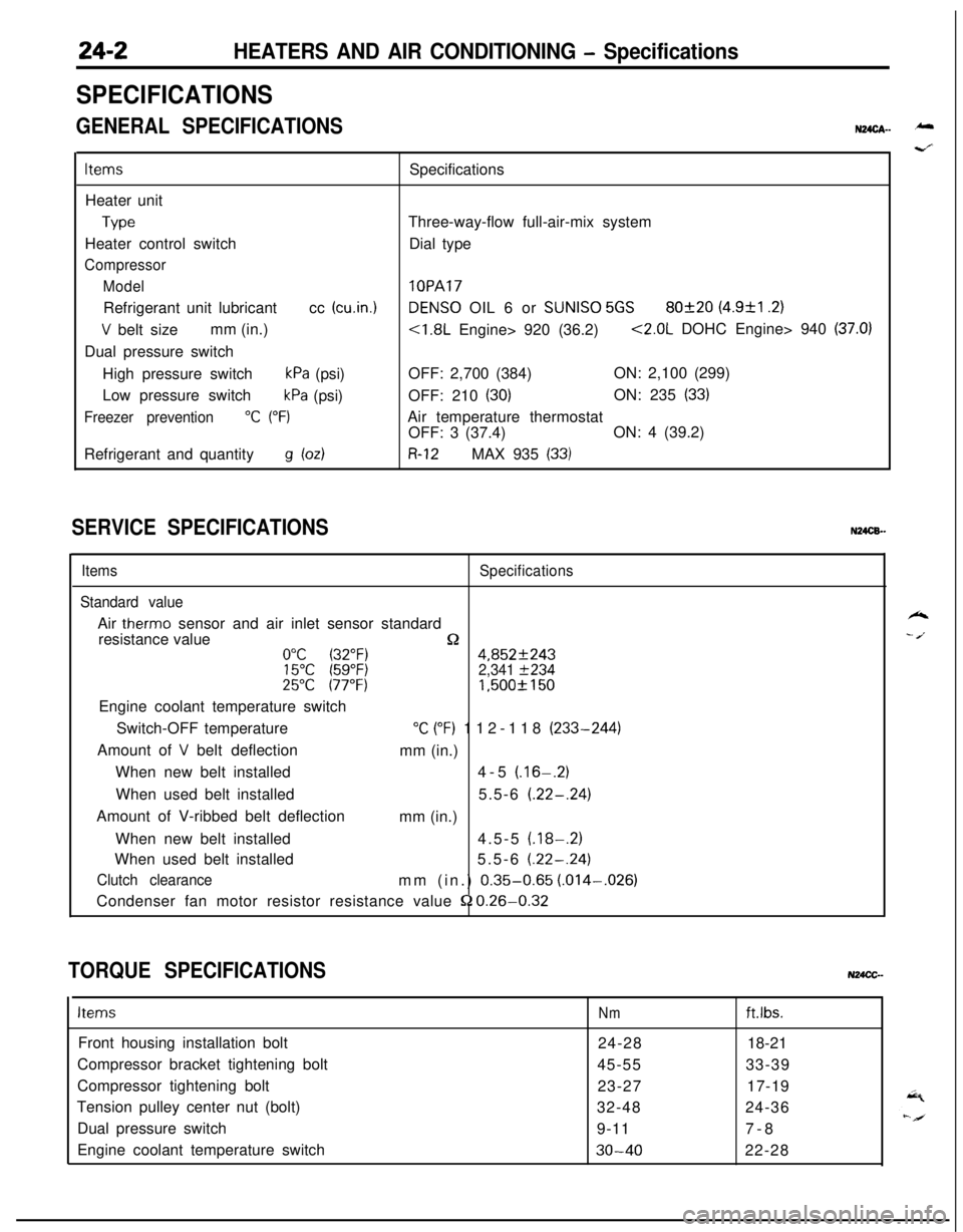
SPECIFICATIONS
GENERAL SPECIFICATIONSN24cA- -
ItemsSpecifications
Heater unit
TypeThree-way-flow full-air-mix system
Heater control switchDial type
Compressor
Model
lOPARefrigerant unit lubricantcc
(cu.in.1DENS0 OIL 6 or SUNISO 5GS80f20 (4.9&l .2)
V belt sizemm (in.)<1.8L Engine> 920 (36.2)<2.0L DOHC Engine> 940 (37.0)Dual pressure switch
High pressure switch
kPa (psi)OFF: 2,700 (384)ON: 2,100 (299)
Low pressure switch
kPa (psi)OFF: 210 (30)ON: 235 (33)
Freezer prevention“C (“F)Air temperature thermostat
OFF: 3 (37.4)ON: 4 (39.2)
Refrigerant and quantity
g bdR-12MAX 935 (33)
SERVICE SPECIFICATIONSN24CB.-
ItemsSpecifications
Standard valueAir
therm0 sensor and air inlet sensor standard
resistance value
n0°C (32°F)4,852f24315°C (59°F)2,341 f23425°C 177°F)1,500f 150Engine coolant temperature switch
Switch-OFF temperature
“C (“F) 112-118 (233-244)
Amount of
V belt deflection
mm (in.)
When new belt installed4-5
(.16-.2)When used belt installed5.5-6
(.22-.24)Amount of V-ribbed belt deflection
mm (in.)
When new belt installed4.5-5
(.18-.2)When used belt installed5.5-6
(.22-.24)
Clutch clearancemm (in.) 0.35-0.65 (.014-,026)
Condenser fan motor resistor resistance value
52 0.26-0.32
TORQUE SPECIFICATIONSN24CC-
ItemsNmft.lbs.Front housing installation bolt
24-2818-21
Compressor bracket tightening bolt
45-5533-39
Compressor tightening bolt
23-2717-19
Tension pulley center nut (bolt)
32-4824-36
Dual pressure switch
9-117-8
Engine coolant temperature switch
30-4022-28
k
- /.
Page 1147 of 1216
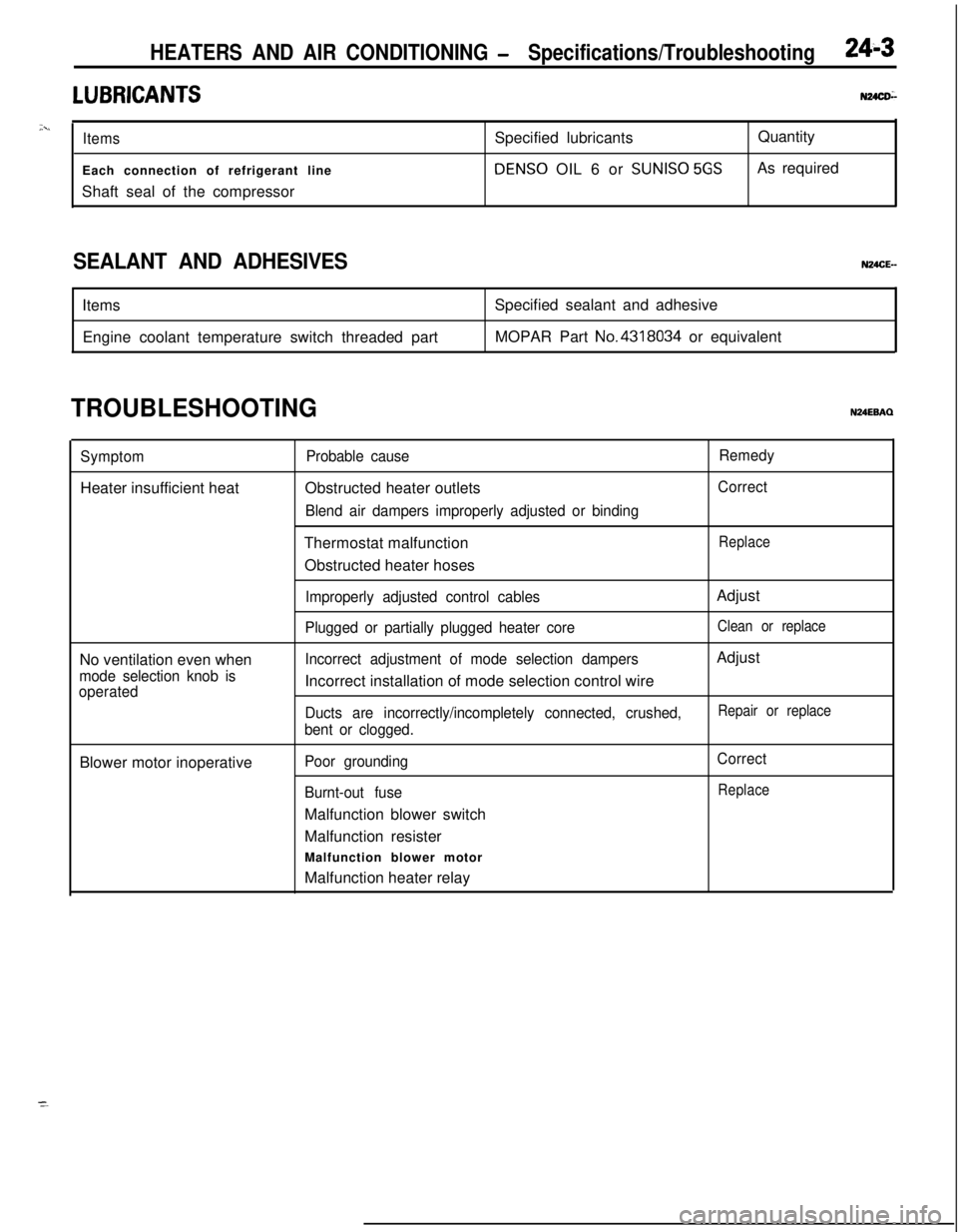
HEATERS AND AIR CONDITIONING - Specifications/Troubleshooting24-3LUBRICANTS
u24as-
;xiItemsSpecified lubricantsQuantity
Each connection of refrigerant lineDENS0 OIL 6 or
SUNISO 5GSAs required
Shaft seal of the compressor
SEALANT AND ADHESIVES, Items
Engine coolant temperature switch threaded partSpecified sealant and adhesive
MOPAR Part No.4318034 or equivalentN24CE-
TROUBLESHOOTINGN24EBAQ
SymptomHeater insufficient heat
No ventilation even when
mode selection knob is
operatedBlower motor inoperative
Probable causeObstructed heater outlets
Blend air dampers improperly adjusted or bindingThermostat malfunction
Obstructed heater hoses
Improperly adjusted control cables
Plugged or partially plugged heater core
Incorrect adjustment of mode selection dampersIncorrect installation of mode selection control wire
Ducts are incorrectly/incompletely connected, crushed,
bent or clogged.
Poor grounding
Burnt-out fuseMalfunction blower switch
Malfunction resister
Malfunction blower motor
Malfunction heater relay
Remedy
Correct
ReplaceAdjust
Clean or replaceAdjust
Repair or replace
Correct
Replace
Page 1197 of 1216
.^
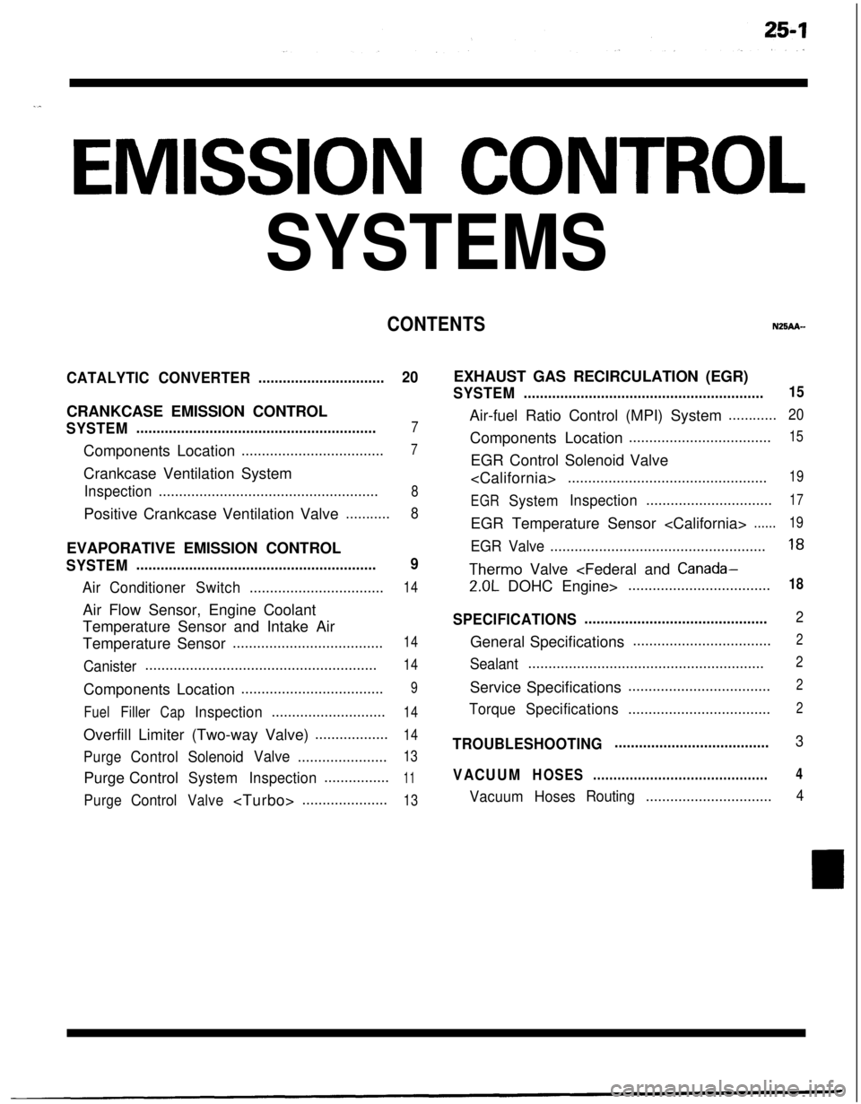
EMISSION CONTROL
SYSTEMS
CONTENTSN25AA-
CATALYTICCONVERTER...............................20CRANKCASE EMISSION CONTROL
SYSTEM...........................................................7Components Location
...................................7Crankcase Ventilation System
Inspection......................................................8Positive Crankcase Ventilation Valve
...........8EVAPORATIVE EMISSION CONTROL
SYSTEM...........................................................9
AirConditionerSwitch.................................14Air Flow Sensor, Engine Coolant
Temperature Sensor and Intake Air
Temperature Sensor
.....................................14
Canister.........................................................14Components Location
...................................9
FuelFillerCapInspection............................14Overfill Limiter (Two-way Valve)
..................14
PurgeControlSolenoidValve......................13Purge Control
SystemInspection................11
PurgeControlValve
SYSTEM...........................................................15Air-fuel Ratio Control (MPI) System
............20Components Location
...................................15EGR Control Solenoid Valve
.................................................19
EGR
SystemInspection...............................17EGR Temperature Sensor
......19
EGR Valve.....................................................18
Therm0 Valve
SPECIFICATIONS.............................................2General Specifications
..................................2
Sealant..........................................................2Service Specifications
...................................2
TorqueSpecifications...................................2
TROUBLESHOOTING......................................3
VACUUMHOSES...........................................4
VacuumHosesRouting...............................4
Page 1198 of 1216
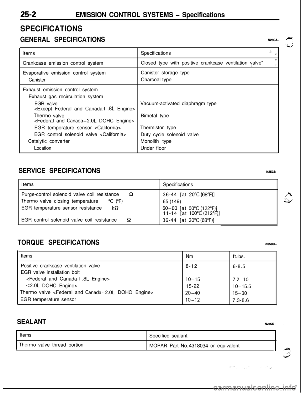
EMISSION CONTROL SYSTEMS - Specifications
SPECIFICATIONS
GENERAL SPECIFICATIONSN25CA-ItemsSpecifications
.,:..rCrankcase emission control systemClosed type with positive crankcase ventilation valve”I
‘:Evaporative emission control systemCanister storage type
CanisterCharcoal type
Exhaust emission control system
Exhaust gas recirculation system
EGR valveVacuum-activated diaphragm type
Therm0 valveBimetal type
EGR temperature sensor
EGR control solenoid valve
Duty cycle solenoid valve
Catalytic converterMonolith type
LocationUnder floor
SERVICE SPECIFICATIONSN25CB-
ItemsSpecifications
Purge-control solenoid valve coil resistance
&236-44 [at 20°C (68”F)I
Therm0 valve closing temperature“C (“F)65 (149)
EGR temperature sensor resistance
kQ60-83 [at 50°C (122”F)]11-14 [at
100°C (212”F)]EGR control solenoid valve coil resistance
S236-44 [at 20°C (68”F)]
TORQUE SPECIFICATIONSN25CC-
ItemsPositive crankcase ventilation valve
EGR valve installation bolt
<2.0L DOHC Engine>
Therm0 valve
EGR temperature sensor
Nmftlbs.8-12
6-8.5
IO-157.2-1015-22
10-15.5
20-4015-30
10-127.3-8.6
SEALANT
Items
Therm0 valve thread portionSpecified sealant
MOPAR Part No.4318034 or equivalent