1991 MITSUBISHI 3000GT bulb
[x] Cancel search: bulbPage 118 of 1146

13-12FUEL SYSTEM - Troubleshooting
MALFUNCTION INDICATOR LIGHT INSPECTION
(1) Check that when the ignition switch is turned on, the lightilluminates for about 5 seconds and then goes out.
(2) If the light does not illuminate, check for open circuit in
dharness, blown fuse and blown bulb.
SELF-DIAGNOSIS
The engine control unit monitors the input/output signals (some
signals at all times and the others under specified conditions) ofthe engine control unit.
When it is noticed that an irregularity has continued for a
specified time or longer from when the irregular signal is
initially monitored, passing a certain number, the engine controlunit judges that an irregularity has occurred, memorizes the
malfunction code, and outputs the signal to the self-diagnosis
output terminal.
There are 21 diagnosis items, including the normal state, andthe diagnosis results can be read out with a voltmeter or
multi-use tester.Moreover, since memorization of the malfunction codes is
backed up directly by the battery, the diagnosis results are
memorized even if the ignition key is turned off. The malfunc-
tion codes will, however, be erased when the battery terminalor the engine control unit connector is disconnected.
The malfunction code can also be erased by turning on the
ignition switch and sending the malfunction code erase signalfrom the multi-use tester to the engine control unit.
CautionIf the sensor connector is disconnected with the ignition
_ _switch turned on, the malfunction code is memorized. Ind
this case, send the malfunction code erase signal from themulti-use tester to the engine control unit or disconnect
the battery terminal
(-) for 10 seconds or more, and the
diagnosis memory will be erased.
The 21 diagnosis items are provided as follows, and if plural
items are activated, they are all indicated sequentially from the
smallest code number.
CautionThe malfunction code for the ignition timing adjustment
signal is output when the line of the ignition timing
adjustment terminal is shorted to ground. Therefore, the
malfunction code is also output when the ignition timing
adjustment terminal is grounded to adjust the ignition
timing, but this does not show any abnormality.
TSB Revision
Page 268 of 1146

13-162CRUISE CONTROL SYSTEM - Troubleshooting
Trouble symptomProbable causeCheck chart No.
Remedy
Cannot accelerate or resume speedOpen or short circuit in
No. 2by using the RESUME switch.RESUME switch circuit inReplace the control switch
control switch
Vacuum pump assemblyNo. 5circuit poor contactRepair the harness or
replace the vacuum pump
Malfunction of thevacuum pump assembly
(including air leaks
from negative pressurepassage)assembly.
Malfunction of the ECU-Replace the ECU.
Even when CANCEL switch is set toON, cruise control is not canceled
Open or short circuit
in CANCEL switchIf the input check
Replace the control switch
(Cruise control, however, iscode No. 27 indicatescircuit in control switch
canceled when brake pedal isa malfunction.
depressed.)No. 2
Malfunction of the ECU-Replace the ECU
The cruise control system can be set
Malfunction of theNo. 4while traveling at a vehicle speedvehicle-speed sensorRepair the vehicle speed
of less than 40 km/h (25 mph), or
circuitsensor system, or replace
there is no automatic cancellationthe part.
at that speed.Malfunction of thespeedometer cable orthe speedometer drive
gear
Malfunction of the ECU
-Replace the ECU.
The cruise control indicator light
No. 3
of the combination meter does notDamaged or disconnectedbulb of indicator lightRepair the harness or
illuminate. (But cruise controlreplace the light bulb.
system is normal)Harness damaged or
disconnected
Malfunction of the ECU
-Replace the ECU.
Cruise control ON indicator light
No. 3
does not come on. (However, cruiseBurned-out indicator lightbulbRepair the harness or
control is functional.)replace the main switch.
Open or short circuit in
harness
Malfunction of control functionby
ON/OFF switching of ELC 4 AA
accelerator switch.
(Non-operation of damper clutch,
2nd gear hold, etc.)
Overdrive is not canceled during
fixed speed driving
No shift to overdrive during
manual driving.
Malfunction of circuitrelated to acceleratorswitch OFF function
Malfunction of the ECU
Malfunction of circuit
related to overdrive
cancellation, or mal-
function of ECU
No. IO
No. 11Repair the harness or
replace the part.
Repair the harness or
replace the part.
TSB Revision
Page 671 of 1146

ELECTRONIC CONTROL SUSPENSION (ECS) - Troubleshooting:33B-9
1 5 1 ECS indicator light does not switch when ECS switch is operated.
Yes
Does ECS indicator light flash?+Read diagnosis code and check area associated with dralgnosrs.---IIIcode.
Disconnect ECS switch connector
and check harness connector with
- No
No. 10 terminal voltage and
continuity between No. 11 terminal
and ground up to specification?Standards:
No.
10 terminal
5 V
No. 11 terminal
Continuity provided
YesCorrect harness.
Check ECS switch. (Refer to P.33B-
YesReplace ECS switch.
check ECS indicator light for burntReplace ECS indicator light bulb.
Is continuity provided across the- Correct harness.
combination meter andECS control unit
No. 10 and 2 terminals
No. 11 and 3 terminals
Yes
”No
Is continuity provided between No. 2> Correct harness.
terminal of combination meter andground?
I
Yes
No
Is trouble cleared by replacingcombination meter?
-Replace ECS control unit.
IYesTSB Revision
Page 748 of 1146

35-26SERVICE BRAKES -Anti-lock Braking System TroubleshootingI
TROUBLESHOOTING (ABS - AWD)Confirm condition in the following way and diagnosis accordingly.
Does the ABS warning light illuminate as described
below up to the time the engine starts?(2) With the ignition key in the “START” position,
(1) When the ignition key is turned to the “ON”power to the ABS ECU is interrupted and the
position, the ABS ECU causes the ABS warningABS warning light remains lit because the valve
relay is OFF.
light to flash four times in about one second (3) When the ignition key is returned from the
(during which the valve relay self check is made)
and then causes it to go out.“START” position to the “ON” position, the
ABS warning light flashes four times in about
one second (during which the valve relay self
-check is made again) and then goes out.
III
OFFu--I-II
ST
ONACC, LOCK
114A0594Yes
>CONTINUED ON NEXT PAGE
No
No.
Trouble condition
Major causesRemedy
1ABS warning light does not light up at all.l ABS warning light bulb is burnt out.
ACC,LOb--
l Open in ABS warning light electricalCheck, using flowchart A (Refer to
ABScircuit (check for blown fuse)P.35-31.)warningOFFlight
lgmtlon
key
14AO590
2When the ignition key is turned to the
“ON” position, it remains lighted.l Fail safe is functioning due to ECU
self diagnosis.Check, using flowchart B (Refer toABS,“,F
J-l Short in ECU warning light drive circuitP.35-34.)warningl Malfunction of ECUlight
Ignition
key.;i,LOi h
3Does not illuminate when ignition key is
in “START” position.l Malfunction of valve relayl Break in harness between ABS warningCheck, using flowchart C (Refer to
light and HUP.35-36.)l Break in harness between HU andwarning
body ground
TSB Revision1
Page 985 of 1146

INTERIOR - Troubleshooting52A-7OPERATION
Key-reminder warning
L0 Battery voltage is always supplied, through
fusible link No. 6 to the key-reminder switch.
l When the driver’s seat is opened while the
ignition key is still in the key cylinder, the door
switch is switched ON, electricity flows to
fusible link No. 6, the key-reminder switch, the
buzzer, the door switch, and ground, and the
buzzer sounds.
Seat belt warning
lBattery voltage is applied, through fuse No. 11
to the ETACS unit when the ignition key is at the
“ON” position.
l Electricity flows to fusible link No. 6, the seat
belt warning light, the ETACS unit, and ground,
and the seat belt warning light flashes for
approx. 6 seconds.
lIf the driver does not buckle the seat belt, the
seat belt switch is switched ON, electricity
flows to fusible link No. 6, the key-reminder
switch, the buzzer, the seat belt switch, the
ETACS unit, and ground, and the buzzer sounds
for approx. 6 seconds.
lWhen the driver buckles the seat belt, the seat
belt switch is switched OFF and the buzzer
stops.
COMPONENT LOCATION
Name1 Symbol (
ETACS unitIA t19FO134TROUBLESHOOTING HINTS
Key-reminder warning
The key-reminder warning doesn’t sound.
(I) The seat belt warning function is OK.
l Check the door switch.
(2) The seat belt warning also doesn’t function.
l Check the buzzer.
Seat belt warning
1. The seat belt warning doesn’t function.
(I) The seat belt warning light flashes.
l Check the seat belt switch.
(2) The seat belt warning light also does not
function (and the key-reminder warning also
does not function).
l Check the key-reminder switch.
2. The buzzer doesn’t stop even though the driv-
er’s seat belt has been buckled.
l Check the seat belt switch.
3. The seat belt warning light doesn’t flashes (but
the buzzer sounds).
l Check the light bulb.
NOTEFor the inspection of the ETACS unit, refer to
P.52A-25.16FO35
1 TSB Revision
Page 1004 of 1146

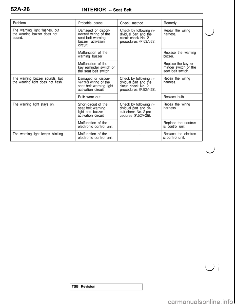
52A-26
INTERIOR - Seat Belt
Problem
The warning light flashes, but
the warning buzzer does not
sound.Probable cause
Damaged or discon-netted
wiring of the
seat belt warning
buzzer activationcircuit
Check method
Check by following in-dividual part and the
circuit check No. 2
procedures (P.52A-28).
Remedy
Repair the wiring
harness,
The warning buzzer sounds, but
the warning light does not flash.
The warning light stays on.
The warning light keeps blinking
Malfunction of theReplace the warning
warning buzzerbuzzer.
Malfunction of theReplace the key re-key reminder switch orminder switch or the
the seat belt switchseat belt switch.
Damaged or discon-Check by following in-Repair the wiringnetted wiring of thedividual part and theharness.seat belt warning lightcircuit check No. 2activation circuitprocedures (P.52A-28).
Bulb worn outReplace bulb.
Short-circuit of theCheck by following in-Repair the wiringseat belt warningdividual part and cir-harness.
light and buzzer
cuit check No. 2 pro-activation circuit
cedures (P.52A-28).
Malfunction of theReplace the electron-electronic control unitic control unit.
Malfunction of the-Replace the electron-electronic control unitic control unit.
‘dTSB Revision
Page 1058 of 1146

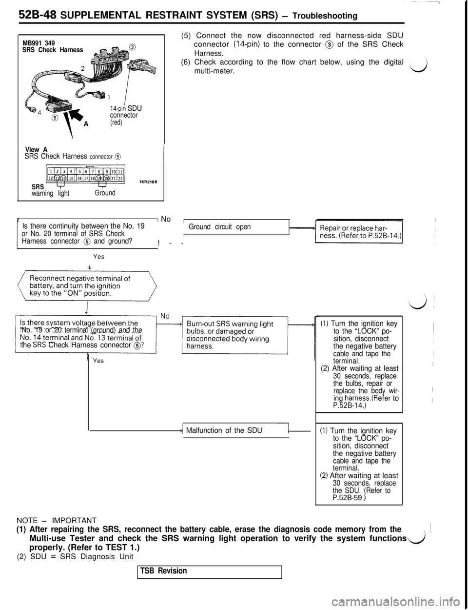
52B-48 SUPPLEMENTAL RESTRAINT SYSTEM (SRS) - Troubleshooting
MB991 349
SRS Check Harness
14-pin SDUconnector(red)
View ASRS Check Harness connector @
SRS
warning lightGround(5) Connect the now disconnected red harness-side SDU
connector
(14-pin) to the connector @ of the SRS Check
Harness.(6) Check according to the flow chart below, using the digital
’multi-meter.drI No
IIs there continuity between the No. 19or No. 20 terminal of SRS Check!--Ground circuit open
Harness connector
@ and ground?Yes
Reconnect negative terminal of
(()
No. 19 or 20 terminal (ground) and the
the SIX Check Harness connector @?Yes
)/ Malfunction of the SDU-1
(1) Turn the ignition key
to the “LOCK” po-
sition, disconnect
the negative battery
cable and tape the
terminal.
(2) After waiting at least30 seconds, replace
the bulbs, repair or
replace the body wir-
ing harness.(Refer toP.52B-14.)
(I ) Turn the ignition key
to the “LOCK” po-
sition, disconnect
the negative battery
cable and tape the
terminal.
(2) After waiting at least30 seconds, replace
the SDU. (Refer to
P.52B-59.)NOTE
- IMPORTANT
(1) After repairing the SRS, reconnect the battery cable, erase the diagnosis code memory from theMulti-use Tester and check the SRS warning light operation to verify the system functions
properly. (Refer to TEST 1.)
d(2) SDU
= SRS Diagnosis Unit
TSB Revision