1991 MITSUBISHI 3000GT lock
[x] Cancel search: lockPage 1001 of 1146
INTERIOR - Front Seat52A-23
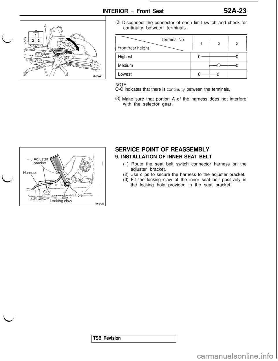
(2) Disconnect the connector of each limit switch and check for
continuity between terminals.
lFr= ) I / * / 3 j
Highest00
Medium0
Lowest0
0
NOTEO-O indicates that there is continurty between the terminals,
(3) Make sure that portion A of the harness does not interfere
with the selector gear.
SERVICE POINT OF REASSEMBLY9. INSTALLATION OF INNER SEAT BELT
(1) Route the seat belt switch connector harness on the
adjuster bracket.
(2) Use clips to secure the harness to the adjuster bracket.
(3) Fit the locking claw of the inner seat belt positively in
the locking hole provided in the seat bracket.
iJ
TSB Revision
Page 1002 of 1146
52A-24INTERIOR - Rear Seat
REAR SEAT
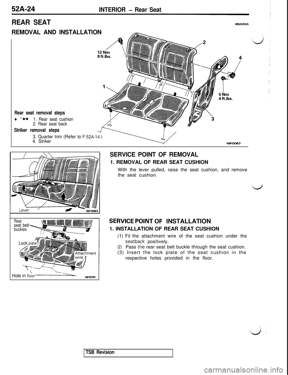
REMOVAL AND INSTALLATION
Rear seat removal steps
l * I)*1. Rear seat cushion
2. Rear seat back
Striker removal steps
3. Quarter trim (Refer to P.52A-14.)4. StrikerlQFtX-I67
Rearseat beltbuckles
Lock dat
Hole in flo\ori-19FOO95
SERVICE POINT OF REMOVAL1. REMOVAL OF REAR SEAT CUSHION
With the lever pulled, raise the seat cushion, and remove
the seat cushion.
SERVICE POINT OF INSTALLATION
1. INSTALLATION OF REAR SEAT CUSHION
(1) Fit the attachment wire of the seat cushion under theseatback positively.
(2)Pass the rear seat belt buckle through the seat cushion.
(3) Insert the lock plate of the seat cushion in the
respective holes provided in the floor.
TSB Revision
Page 1003 of 1146
INTERIOR - Seat Belt52A-25
Diagnosis connector”LJ’2OFOOl
GW161,338
With voltmeter___.-- -- ~~--~_. ___-- ..-.. .-.-
With multi-use tester
SEAT BELTM52UGEH
TROUBLESHOOTING GUIDE
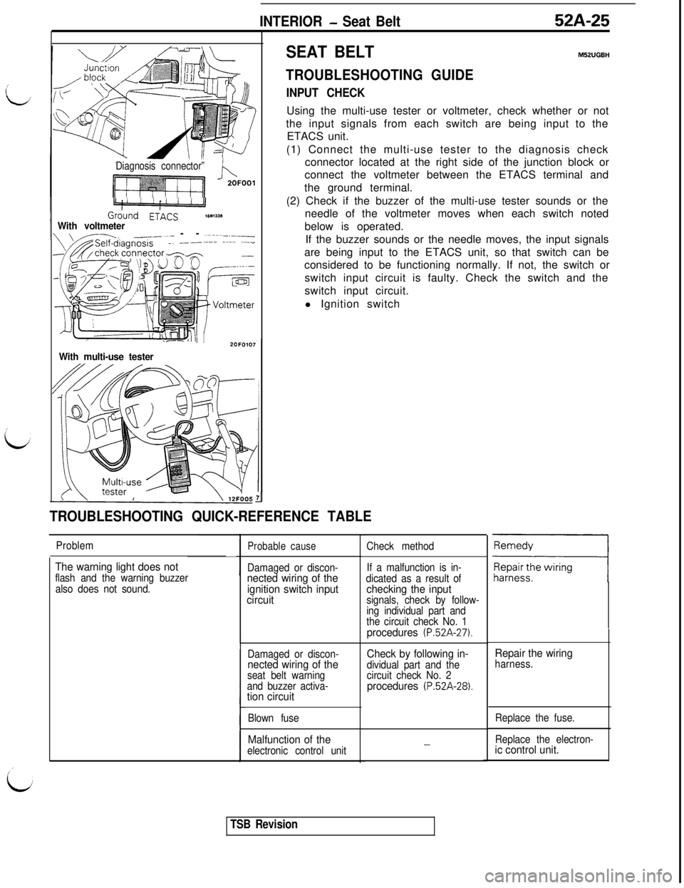
INPUT CHECKUsing the multi-use tester or voltmeter, check whether or not
the input signals from each switch are being input to the
ETACS unit.
(1) Connect the multi-use tester to the diagnosis check
connector located at the right side of the junction block or
connect the voltmeter between the ETACS terminal and
the ground terminal.
(2) Check if the buzzer of the multi-use tester sounds or the
needle of the voltmeter moves when each switch noted
below is operated.
If the buzzer sounds or the needle moves, the input signals
are being input to the ETACS unit, so that switch can be
considered to be functioning normally. If not, the switch or
switch input circuit is faulty. Check the switch and the
switch input circuit.
l Ignition switch
II
TROUBLESHOOTING QUICK-REFERENCE TABLE
Problem
The warning light does notflash and the warning buzzer
also does not sound.
Probable cause
Damaged or discon-nected wiring of the
ignition switch input
circuit
Damaged or discon-nected wiring of theseat belt warning
and buzzer activa-
tion circuit
Blown fuse
Malfunction of theelectronic control unitCheck method
If a malfunction is in-
dicated as a result of
checking the inputsignals, check by follow-
ing individual part and
the circuit check No. 1
procedures (P.52A-27).
Check by following in-dividual part and the
circuit check No. 2
procedures (P.52A-28).
-
Repair the wiringharness.
Replace the fuse.
Replace the electron-
ic control unit.
TSB Revision
Page 1005 of 1146
INTERIOR - Seat Belt52A-27
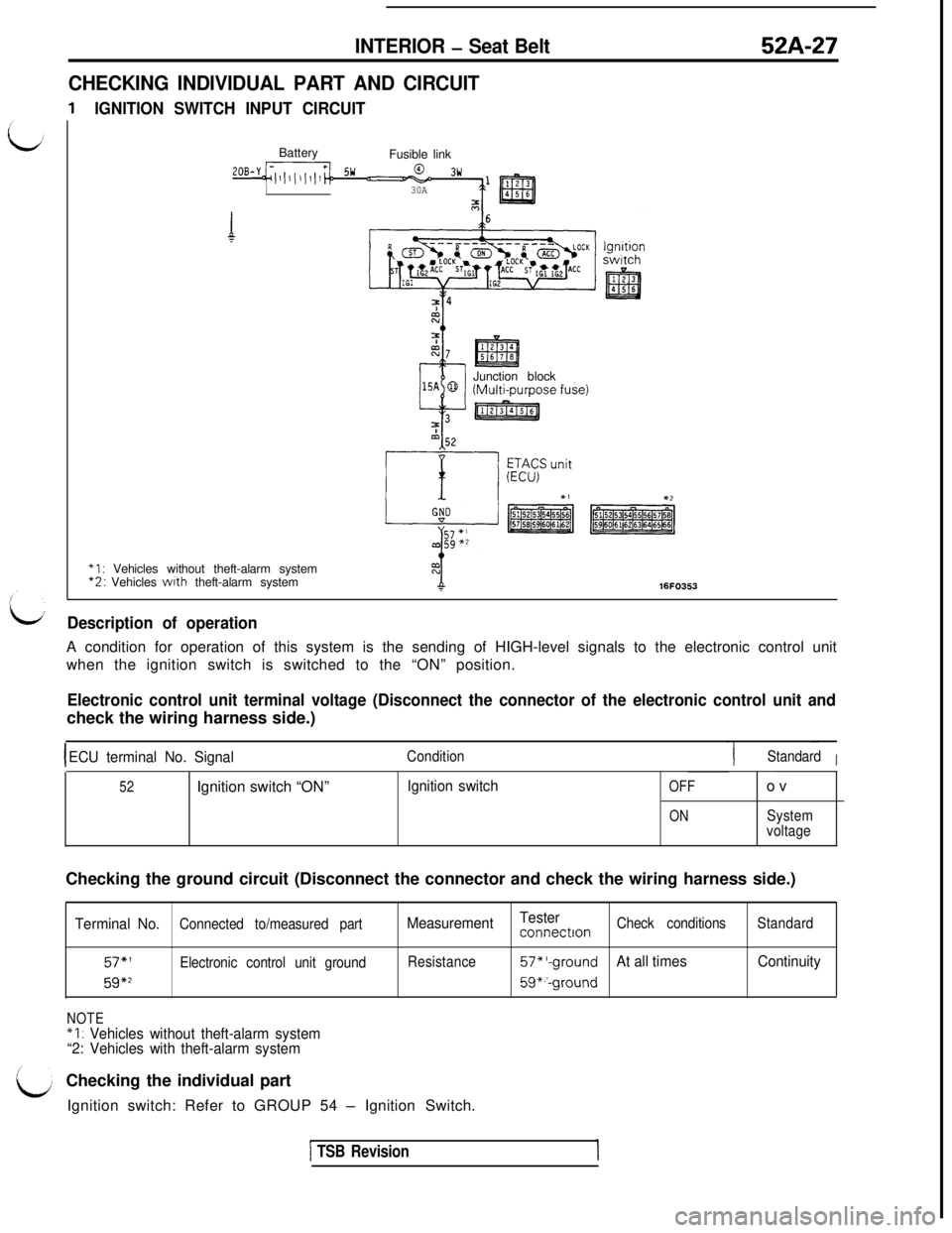
CHECKING INDIVIDUAL PART AND CIRCUIT
IGNITION SWITCH INPUT CIRCUITBattery
Fusible link
2oB-y~~/l,l(l,l,,~~ !jw u03w
30AJunction block
*I : Vehicles without theft-alarm system“2: Vehicles wtth theft-alarm system16FO35.3
It/Description of operationA condition for operation of this system is the sending of HIGH-level signals to the electronic control unit
when the ignition switch is switched to the “ON” position.
Electronic control unit terminal voltage (Disconnect the connector of the electronic control unit andcheck the wiring harness side.)
IECU terminal No. SignalCondition-1 ~StandardI
52Ignition switch “ON”Ignition switchOFF
ONov
System
voltageChecking the ground circuit (Disconnect the connector and check the wiring harness side.)
Terminal No.Connected to/measured part
57,’Electronic control unit ground
59*2
NOTE
*I : Vehicles without theft-alarm system
“2: Vehicles with theft-alarm systemMeasurementTester
connectronCheck conditionsStandard
Resistance
57*‘-groundAt all timesContinuity
59*.‘-groundChecking the individual part
Ignition switch: Refer to GROUP 54
- Ignition Switch.
1 TSB Revision
Page 1006 of 1146
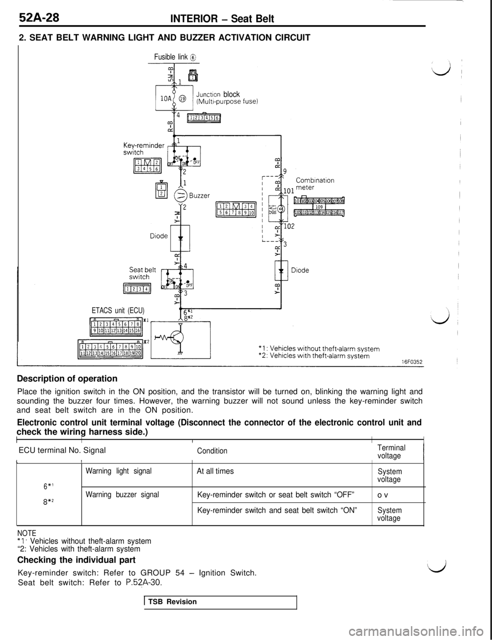
52A-28INTERIOR - Seat Belt2. SEAT BELT WARNING LIGHT AND BUZZER ACTIVATION CIRCUIT
Fusible link @
Junctron block(Multr-purpose fuse)
ETACS unit (ECU)Description of operation
Place the ignition switch in the ON position, and the transistor will be turned on, blinking the warning light and
sounding the buzzer four times. However, the warning buzzer will not sound unless the key-reminder switch
and seat belt switch are in the ON position.
Electronic control unit terminal voltage (Disconnect the connector of the electronic control unit andcheck the wiring harness side.)
IIIIIECU terminal No. Signal
ConditionTerminal
voltageI\!
Warning light signalAt all timesSystem
6*1voltage
Warning buzzer signal
Key-reminder switch or seat belt switch “OFF”ov8*2
Key-reminder switch and seat belt switch “ON”System
voltage
NOTE“1. Vehicles without theft-alarm system
“2: Vehicles with theft-alarm systemChecking the individual part
Key-reminder switch: Refer to GROUP 54
- Ignition Switch.dSeat belt switch: Refer to
P.5?A-30.
1 TSB Revision
Page 1008 of 1146
52A-30
INTERIOR - Seat Belt
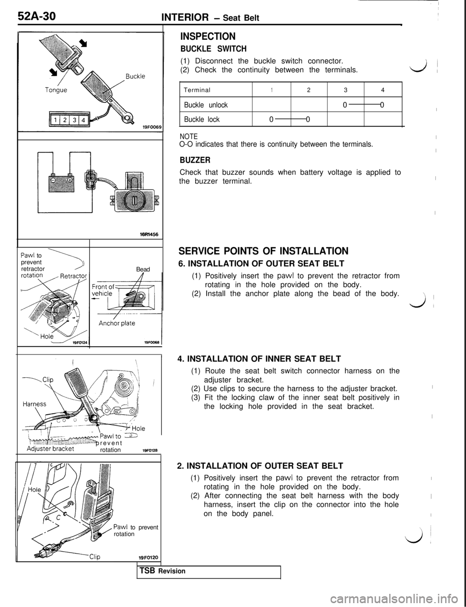
16M456
NOTEO-O indicates that there is continuity between the terminals.
BUZZERCheck that buzzer sounds when battery voltage is applied to
the buzzer terminal.
Paw1 to
prevent
\1retractor
Bead
INSPECTION
BUCKLE SWITCH(1) Disconnect the buckle switch connector.
(2) Check the continuity between the terminals.
Terminal
1234
Buckle unlock00
Buckle lock00
i
“..i,Tlmdsmrawlro -6I J3JJAdjuster’bracketJ’JJ’ prevent
rotation19FO128
Paw1 to prevent
rotation19FO120
SERVICE POINTS OF INSTALLATION6. INSTALLATION OF OUTER SEAT BELT
(1) Positively insert the
paw1 to prevent the retractor from
rotating in the hole provided on the body.
(2) Install the anchor plate along the bead of the body.
4. INSTALLATION OF INNER SEAT BELT
(1) Route the seat belt switch connector harness on the
adjuster bracket.
(2) Use clips to secure the harness to the adjuster bracket.
(3) Fit the locking claw of the inner seat belt positively in
the locking hole provided in the seat bracket.
2. INSTALLATION OF OUTER SEAT BELT
(1) Positively insert the
paw1 to prevent the retractor from
rotating in the hole provided on the body.
(2) After connecting the seat belt harness with the body
harness, insert the clip on the connector into the hole
on the body panel.
LA
I
I
I
I
I\
Jl
I
I
I
I
I
\ ~
L&l
TSB Revision
Page 1011 of 1146
528-l
L’ SUPPLEMENTAL
RESTRAINT
SYSTEM (SRS)
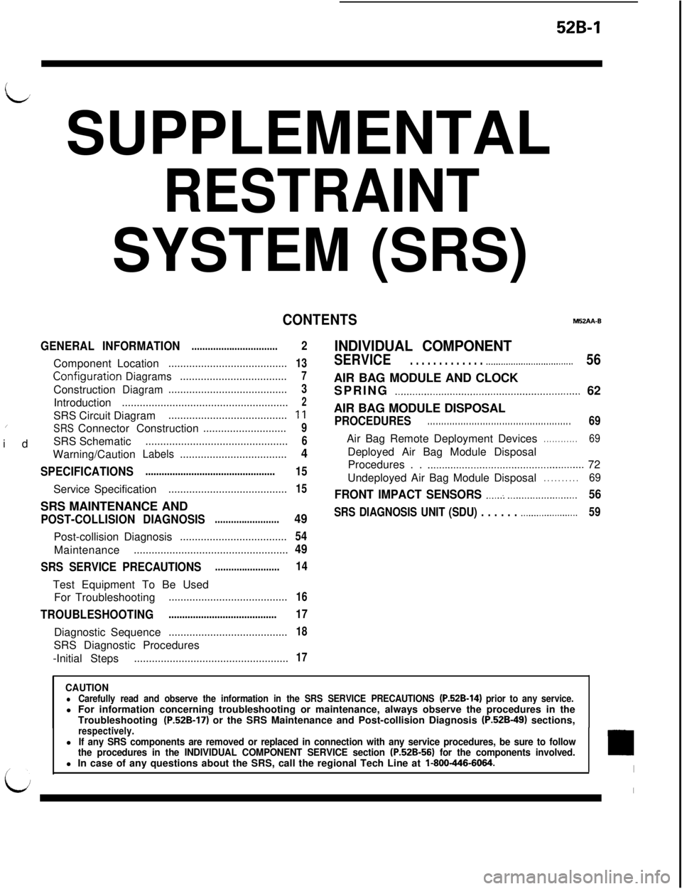
CONTENTSM52AA-B
GENERAL INFORMATION
................................ComponentLocation
........................................
Configurati0.nDiagrams....................................Construction
Diagram........................................Introduction
........................................................SRS Circuit Diagram
......................................../idSRSConnector Construction............................SRS Schematic
................................................Warning/Caution
Labels....................................
SPECIFICATIONS................................................ServiceSpecification
........................................SRS MAINTENANCE AND
POST-COLLISION DIAGNOSIS........................Post-collisionDiagnosis
....................................Maintenance
....................................................
SRS SERVICE PRECAUTIONS........................Test Equipment To Be Used
For Troubleshooting
........................................
TROUBLESHOOTING........................................DiagnosticSequence
........................................SRS Diagnostic Procedures
-Initial Steps
....................................................
2
13
7
3
2
11
9
6
4
15
15
49
54
49
14
16
17
18
17
INDIVIDUAL COMPONENT
SERVICE. . . . . . . . . . . . . .._................................56AIR BAG MODULE AND CLOCK
SPRING
._..........._......................._.........._............... 62
AIR BAG MODULE DISPOSAL
PROCEDURES. . . . . . . . . . . . . . . . . . . . . . . . . . . . . . . . . . . . . . . . . . . . . . . . . . . .69Air Bag Remote Deployment Devices
. . . . . . . . . . . .69Deployed Air Bag Module Disposal
Procedures . .
.._..........._....................................... 72
Undeployed Air Bag Module Disposal
. . . . . . . . . .69
FRONT IMPACT SENSORS ._....: _._..._..................56
SRS DIAGNOSIS UNIT (SDU) . . . . . . .._...................59
CAUTIONlCarefully read and observe the information in the SRS SERVICE PRECAUTIONS (P.52B-14) prior to any service.l For information concerning troubleshooting or maintenance, always observe the procedures in the
Troubleshooting
(P.52B-17) or the SRS Maintenance and Post-collision Diagnosis (P.52B-49) sections,_respectively.lIf any SRS components are removed or replaced in connection with any service procedures, be sure to follow
the procedures in the INDIVIDUAL COMPONENT SERVICE section (P.52B-56) for the components involved.l In case of any questions about the SRS, call the regional Tech Line at l-800-446-6064.
Page 1012 of 1146
52B-2SUPPLEMENTAL RESTRAINT SYSTEM (SRS) - General informationGENERAL INFORMATION
INTRODUCTIONThe Supplemental Restraint System (SRS) is de-
signed to supplement the driver’s seat belt to help
reduce the risk or severity of injury to the driver by
activating and deploying a driver’s-side air bag in
certain frontal collisions.
The SRS consists of: left front and right front impact
sensors located, one each, on the right and left front
upper frame lowers; an air bag module located in
the center of the steering wheel, which contains the
folded air bag and an inflator unit; the SRS diagnosis
unit located under the rear console assembly, which
monitors the system, and which contains a safing
impact sensor; an SRS warning light located on the
instrument panel, which indicates the operational
status of the SRS; a clock spring interconnection
located within the steering column; system wiring
and wiring connectors; and a knee bolster located
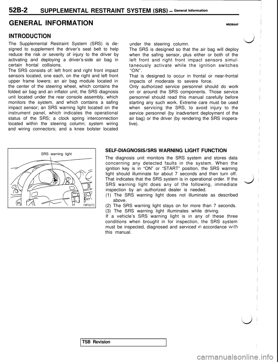
SRS warning light
M52BAAFunder the steering column.
The SRS is designed so that the air bag will deploy
when the safing sensor, plus either or both of the
left front and right front impact sensors simul-
taneously activate while the ignition switches
“ON”.
That is designed to occur in frontal or near-frontal
impacts of moderate to severe force.
Only authorized service personnel should do work
on or around the SRS components. Those service
personnel should read this manual carefully before
starting any such work. Extreme care must be used
whenservicing the SRS, to avoid injury to the
service personnel (by inadvertent deployment of the
air bag) or the driver (by rendering the SRS inopera-
tive).
SELF-DIAGNOSIS/SRS WARNING LIGHT FUNCTION
The diagnosis unit monitors the SRS system and stores data
concerning any detected faults in the system. When the
ignition key is in “ON” or “START” position, the SRS warning
light should illuminate for about 7 seconds and then turn off.
That indicates that the SRS system is in operational order. If the
SRS warning light does any of the following, immediate
inspection by an authorized dealer is needed.
(1) The SRS warning light does not illuminate as described
above.
(2) The SRS warning light stays on for more than 7 seconds.
(3) The SRS warning light illuminates while driving.
If a vehicle’s SRS warning light is in any of these three
conditions when brought in for inspection, the SRS system
must be inspected, diagnosed and serviced
In accordance wrth
this manual.
TSB Revision