Page 1730 of 4087
37. INSTALL A/C COMPRESSOR(a) In sta ll th e A/C co mp re sso r, co mp re sso r sta y an dground cable with the three bolts and nut.
Torque: Bolt 49 N Vm (500 kgf Vcm, 36 ft Vlbf)
Nut 29 N Vm (300 kgf Vcm, 22 ft Vlbf)
(b) Connect the A/C compressor connector.
38. INSTALL RADIATOR AND RESERVOIR TANK (See steps 25 and 26 on pages EM±174 to 175)
39. INSTALL DRIVE BELT Install the drive belt by turning the drive belt tensioner coun-
terclockwise.
HINT: The pully bolt for the belt tensioner has a lefthand
thread.
40. INSTALL BATTERY
41. FILL WITH ENGINE COOLANT (See page CO±7)
42. CHECK IGNITION TIMING (See page IG±28)
Ignition timing:
8±125 BTDC @ idle
(w/ Terminals TE1 and E1 connected)
43. INSTALL ENGINE UNDER COVER
±
ENGINE MECHANICAL Timing BeltEM±57
WhereEverybodyKnowsYourName
Page 1735 of 4087
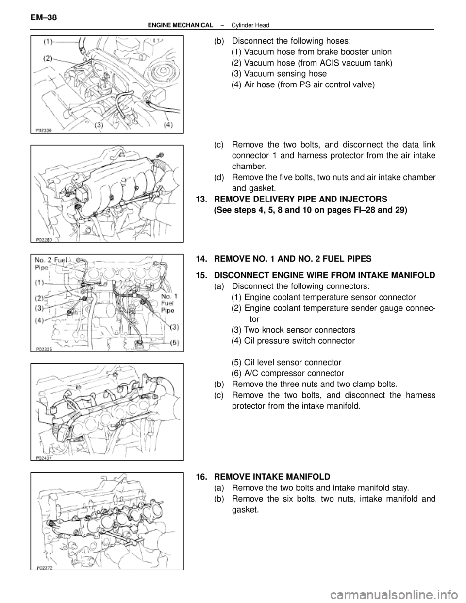
(b) Disconnect the following hoses:(1) Vacuum hose from brake booster union
(2) Vacuum hose (from ACIS vacuum tank)
(3) Vacuum sensing hose
(4) Air hose (from PS air control valve)
(c) Remove the two bolts, and disconnect the data link connector 1 and harness protector from the air intake
chamber.
(d) Remove the five bolts, two nuts and air intake chamber and gasket.
13. REMOVE DELIVERY PIPE AND INJECTORS (See steps 4, 5, 8 and 10 on pages FI±28 and 29)
14. REMOVE NO. 1 AND NO. 2 FUEL PIPES
15. DISCONNECT ENGINE WIRE FROM INTAKE MANIFOLD (a) Disconnect the following connectors:
(1) Engine coolant temperature sensor connector
(2) Engine coolant temperature sender gauge connec- tor
(3) Two knock sensor connectors
(4) Oil pressure switch connector
(5) Oil level sensor connector
(6) A/C compressor connector
(b) Remove the three nuts and two clamp bolts.
(c) Remove the two bolts, and disconnect the harness
protector from the intake manifold.
16. REMOVE INTAKE MANIFOLD (a) Remove the two bolts and intake manifold stay.
(b) Remove the six bolts, two nuts, intake manifold andgasket.
EM±38
±
ENGINE MECHANICAL Cylinder Head
WhereEverybodyKnowsYourName
Page 1739 of 4087
3. REMOVE ENGINE HANGERS
4. REMOVE ENGINE COOLANT TEMPERATURE SENSORAND SENDER GAUGE
5. REMOVE THROTTLE CABLE BRACKET AND GROUND STRAP
6. REMOVE EGR COOLER
INSPECTION, CLEANING AND REPAIR
OF CYLINDER HEAD COMPONENTS
1. CLEAN TOP SURFACES OF PISTONS AND CYLINDER BLOCK
(a) Turn the crankshaft, and bring each piston to top deadcenter (TDC). Using a gasket scraper, remove all the
carbon from the piston top surface.
(b) Using a gasket scraper, remove all the gasket material from the top surface of the cylinder block.
(c) Using compressed air, blow carbon and oil from the bolt
holes.
CAUTION: Protect your eyes when using high±com-
pressed air.
2. CLEAN CYLINDER HEAD
A. Remove gasket material Using a gasket scraper, remove all the gasket material from
the cylinder block surface.
NOTICE: Be careful not to scratch the cylinder block con-
tact surface.
EM±42
±
ENGINE MECHANICAL Cylinder Head
WhereEverybodyKnowsYourName
Page 1749 of 4087
ASSEMBLY OF CYLINDER HEAD
(See Components on page EM±35)HINT:
wThoroughly clean all parts to be assembled.
w Before installing the parts, apply new engine oil to all
sliding and rotating surfaces.
w Replace all gaskets and oil seals with new ones.
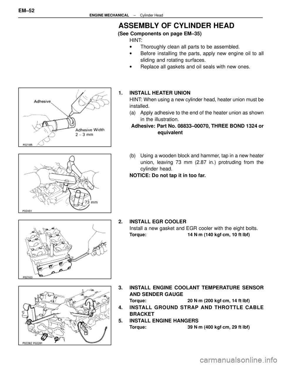
1. INSTALL HEATER UNION HINT: When using a new cylinder head, heater union must be
installed.
(a) Apply adhesive to the end of the heater union as shownin the illustration.
Adhesive: Part No. 08833±00070, THREE BOND 1324 or equivalent
(b) Using a wooden block and hammer, tap in a new heater
union, leaving 73 mm (2.87 in.) protruding from the
cylinder head.
NOTICE: Do not tap it in too far.
2. INSTALL EGR COOLER Install a new gasket and EGR cooler with the eight bolts.
Torque: 14 N Vm (140 kgf Vcm, 10 ft Vlbf)
3. INSTALL ENGINE COOLANT TEMPERATURE SENSOR
AND SENDER GAUGE
Torque: 20 N Vm (200 kgf Vcm, 14 ft Vlbf)
4. INSTALL GROUND STRAP AND THROTTLE CABLE
BRACKET
5. INSTALL ENGINE HANGERS
Torque: 39 N Vm (400 kgf Vcm, 29 ft Vlbf)
EM±52±
ENGINE MECHANICAL Cylinder Head
WhereEverybodyKnowsYourName
Page 1756 of 4087
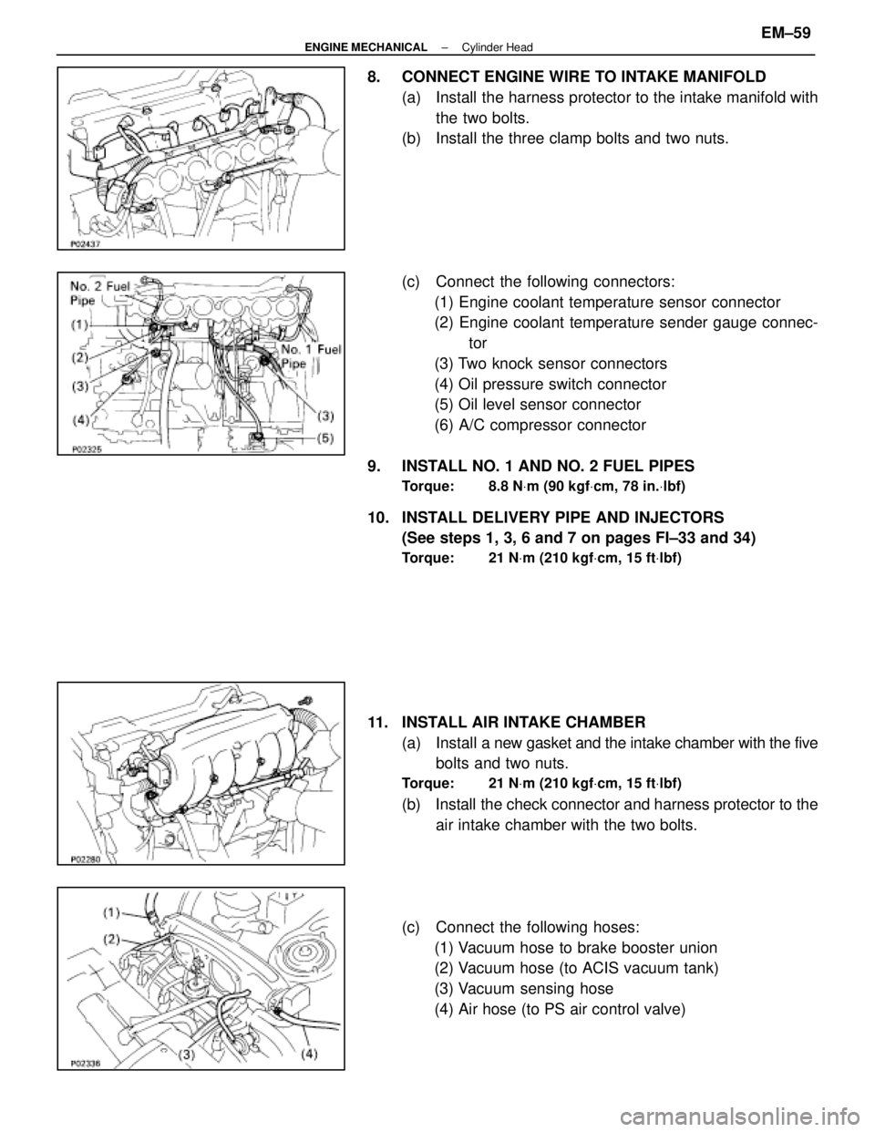
8. CONNECT ENGINE WIRE TO INTAKE MANIFOLD(a) Install the harness protector to the intake manifold withthe two bolts.
(b) Install the three clamp bolts and two nuts.
(c) Connect the following connectors:
(1) Engine coolant temperature sensor connector
(2) Engine coolant temperature sender gauge connec- tor
(3) Two knock sensor connectors
(4) Oil pressure switch connector
(5) Oil level sensor connector
(6) A/C compressor connector
9. INSTALL NO. 1 AND NO. 2 FUEL PIPES
Torque: 8.8 N Vm (90 kgf Vcm, 78 in. Vlbf)
10. INSTALL DELIVERY PIPE AND INJECTORS
(See steps 1, 3, 6 and 7 on pages FI±33 and 34)
Torque: 21 N Vm (210 kgf Vcm, 15 ft Vlbf)
11. INSTALL AIR INTAKE CHAMBER
(a) Install a new gasket and the intake chamber with the five
bolts and two nuts.
Torque: 21 N Vm (210 kgf Vcm, 15 ft Vlbf)
(b) Install the check connector and harness protector to the
air intake chamber with the two bolts.
(c) Connect the following hoses: (1) Vacuum hose to brake booster union
(2) Vacuum hose (to ACIS vacuum tank)
(3) Vacuum sensing hose
(4) Air hose (to PS air control valve)
±
ENGINE MECHANICAL Cylinder HeadEM±59
WhereEverybodyKnowsYourName
Page 1758 of 4087
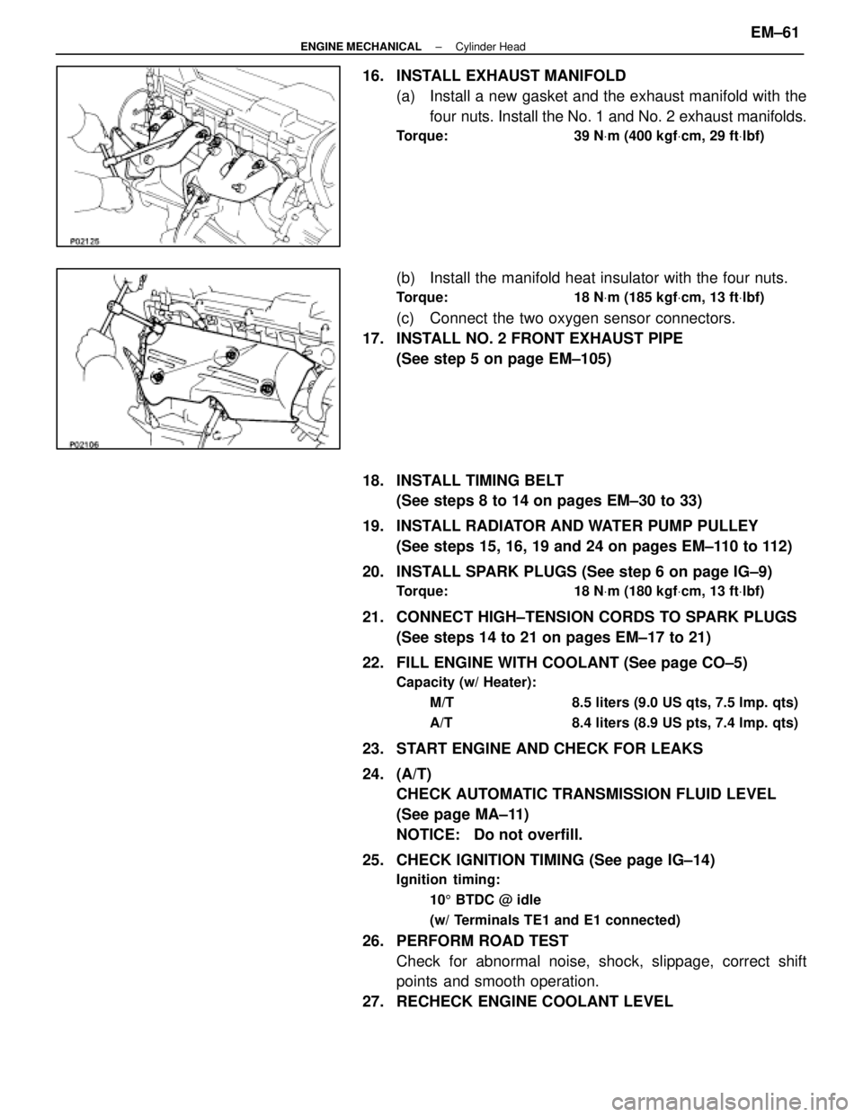
16. INSTALL EXHAUST MANIFOLD(a) Install a new gasket and the exhaust manifold with thefour nuts. Install the No. 1 and No. 2 exhaust manifolds.
Torque: 39 N Vm (400 kgf Vcm, 29 ft Vlbf)
(b) Install the manifold heat insulator with the four nuts.
Torque: 18 N Vm (185 kgf Vcm, 13 ft Vlbf)
(c) Connect the two oxygen sensor connectors.
17. INSTALL NO. 2 FRONT EXHAUST PIPE (See step 5 on page EM±105)
18. INSTALL TIMING BELT (See steps 8 to 14 on pages EM±30 to 33)
19. INSTALL RADIATOR AND WATER PUMP PULLEY (See steps 15, 16, 19 and 24 on pages EM±110 to 112)
20. INSTALL SPARK PLUGS (See step 6 on page IG±9)
Torque: 18 N Vm (180 kgf Vcm, 13 ft Vlbf)
21. CONNECT HIGH±TENSION CORDS TO SPARK PLUGS
(See steps 14 to 21 on pages EM±17 to 21)
22. FILL ENGINE WITH COOLANT (See page CO±5)
Capacity (w/ Heater): M/T 8.5 liters (9.0 US qts, 7.5 lmp. qts)
A/T 8.4 liters (8.9 US pts, 7.4 lmp. qts)
23. START ENGINE AND CHECK FOR LEAKS
24. (A/T)CHECK AUTOMATIC TRANSMISSION FLUID LEVEL
(See page MA±11)
NOTICE: Do not overfill.
25. CHECK IGNITION TIMING (See page IG±14)
Ignition timing: 105 BTDC @ idle
(w/ Terminals TE1 and E1 connected)
26. PERFORM ROAD TEST Check for abnormal noise, shock, slippage, correct shift
points and smooth operation.
27. RECHECK ENGINE COOLANT LEVEL
±
ENGINE MECHANICAL Cylinder HeadEM±61
WhereEverybodyKnowsYourName
Page 1819 of 4087
COMPONENTS FOR REMOVAL AND
INSTALLATION OF ENGINE WITH
TRANSMISSION (Cont'd)
REMOVAL OF ENGINE WITH
TRANSMISSION
1. REMOVE BATTERYCAUTION: Turn the ignition switch to ºLOCKº. Discon-
nect the cable from the negative (±) terminal of the bat-
tery. Wait at least 20 seconds before proceeding with
work.
2. REMOVE ENGINE UNDER COVER
3. DRAIN ENGINE COOLANT
4. DISCONNECT CONTROL CABLES FROM THROTTLE BODY
Disconnect the following cables:(1) Accelerator cable
(2) (A/T)Throttle control cable
(3) Cruise control actuator cable
EM±64
±
ENGINE MECHANICAL Cylinder Block
WhereEverybodyKnowsYourName
Page 1867 of 4087
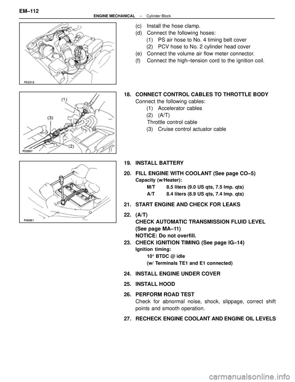
(c) Install the hose clamp.
(d) Connect the following hoses:(1) PS air hose to No. 4 timing belt cover
(2) PCV hose to No. 2 cylinder head cover
(e) Connect the volume air flow meter connector.
(f) Connect the high±tension cord to the ignition coil.
18. CONNECT CONTROL CABLES TO THROTTLE BODY Connect the following cables:(1) Accelerator cables
(2) (A/T)
Throttle control cable
(3) Cruise control actuator cable
19. INSTALL BATTERY
20. FILL ENGINE WITH COOLANT (See page CO±5)
Capacity (w/Heater): M/T 8.5 liters (9.0 US qts, 7.5 lmp. qts)
A/T 8.4 liters (8.9 US qts, 7.4 lmp. qts)
21. START ENGINE AND CHECK FOR LEAKS
22. (A/T)CHECK AUTOMATIC TRANSMISSION FLUID LEVEL
(See page MA±11)
NOTICE: Do not overfill.
23. CHECK IGNITION TIMING (See page IG±14)
Ignition timing:
105 BTDC @ idle
(w/ Terminals TE1 and E1 connected)
24. INSTALL ENGINE UNDER COVER
25. INSTALL HOOD
26. PERFORM ROAD TEST Check for abnormal noise, shock, slippage, correct shift
points and smooth operation.
27. RECHECK ENGINE COOLANT AND ENGINE OIL LEVELS
EM±112
±
ENGINE MECHANICAL Cylinder Block
WhereEverybodyKnowsYourName