Page 643 of 4087
28CD playerSOUND QUALITY POOR
Is radio operating normally?
Is speaker properly installed? Temporarily install another speaker
Functions OK? Temporarily install another CD auto changer.
Functions OK?
Temporarily install another power amplifier.
Functions OK? Radio receiver assembly faulty. Speaker faulty. Speaker installation faulty
Power amplifier faulty. Radio receiver assem-
bly faulty CD changer faulty.
29CD playerVOLUME REMAINS AT MAXIMUM LEVEL
Is radio operating normally?
Radio receiver assembly faulty.
Wire harness faulty.
Is there continuity between the following terminals
with connector disconnected?
� Radio receiver assembly B1 ± Power switch 14
� Radio receiver assembly B3 ± Power switch 11
Power switch faulty.
Radio receiver assembly faulty.
When the volume switch is turned from minimum to
maximum, does resistance between terminal 11±14
of power switch changes from 0 to 50 k
�?
±
BODY ELECTRICAL SYSTEM AUDIO SYSTEMBE±257
WhereEverybodyKnowsYourName
Page 644 of 4087
30NoiseNOISE PRODUCED BY VIBRATION OR SHOCK
WHILE DRIVING
Is radio properly installed?
Is radio receiver assembly properly installed?
*1 Is radio power amplifier properly installed?
*2 Is woofer amplifier properly installed?*1 Is CD auto changer properly installed?
With vehicle stopped, lightly tap each part.
Is noise produced? Speaker installation faulty.
Radio receiver assembly installation faulty.
Power amplifier installation faulty.
Woofer amplifier installation faulty.
CD auto changer installation faulty. Each part faulty.
Noise produced by static electricity is accululating in the vehicle body\
.
BE±258±
BODY ELECTRICAL SYSTEM AUDIO SYSTEM
WhereEverybodyKnowsYourName
Page 645 of 4087
31NoiseNOISE PRODUCED WHEN ENGINE STARTS
Whistling noise which becomes high±pitched when
accelerator strongly depressed, disappears shortly
after engine stops.Whining noise occurs when A/C is operating.
Scratching noise occurs during sudden accel-
eration, driving on rough roads or when ignition
switch is turned on.
Clicking sound heard when horn button is
pressed, then released. Whirring/grating sound
when pushed continuously.
Murmuring sound, stops when engine stops. Tick±tock noise, occurs in coordination with
blinking of flasher.
Noise occurs during window washer operation.Scratching noise occurs while engine is running,
continues a while even after engine stops.Scraping noise in time with wiper beat.
Other type of noise. Alternator noise.
A/C noise.
Fuel gauge noise.
Horn noise.
Ignition noise. Turn signal flasher noise.
Washer noise. Water temp. gauge noise.
Wiper noise.
±
BODY ELECTRICAL SYSTEM AUDIO SYSTEMBE±259
WhereEverybodyKnowsYourName
Page 646 of 4087

32AntennaANTENNA±RELATED
Does antenna extend when radio switched ON?Wire harness faulty.
Is there battery voltage between the following
terminals with connector disconnected?
�
Motor antenna control relay 6 ± ground
� Motor antenna control relay 14 ± ground
� Motor antenna control relay 3 ± ground
Wire harness faulty.Replace fuses.
Radio receiver assembly faulty.
Check if ECU±IG, RADIO No. 1 and RADIO No.
2 fuse are OK.
ªAMº button turned ON.
Is there battery voltage between the following
terminals with connector connected?
� Radio receiver assembly A9 (*A1) ± ground
� Radio receiver assembly A8 ± ground
� Radio receiver assembly D4 ± ground
� Radio receiver assembly D10 ± ground Radio receiver side
faulty.
Motor antenna faulty.
Temporarily install another motor antenna is
radio operating normally?
Glass printed antenna faulty.
Check if glass printed antenna is OK.
Is there continuity between the following terminals
with connector disconnected?
� Motor antenna control relay 4 ± ground
Continued on next page.
BE±260±
BODY ELECTRICAL SYSTEM AUDIO SYSTEM
WhereEverybodyKnowsYourName
Page 647 of 4087
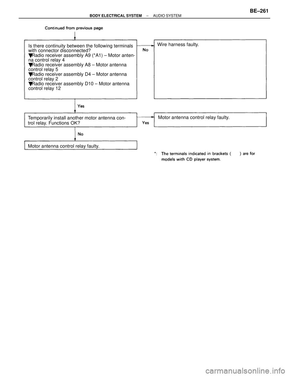
Wire harness faulty.
Is there continuity between the following terminals
with connector disconnected?
� Radio receiver assembly A9 (*A1) ± Motor anten-
na control relay 4
� Radio receiver assembly A8 ± Motor antenna
control relay 5
� Radio receiver assembly D4 ± Motor antenna
control relay 2
� Radio receiver assembly D10 ± Motor antenna
control relay 12
Temporarily install another motor antenna con-
trol relay. Functions OK? Motor antenna control relay faulty.
Motor antenna control relay faulty.
±
BODY ELECTRICAL SYSTEM AUDIO SYSTEMBE±261
WhereEverybodyKnowsYourName
Page 803 of 4087

PRECAUTIONS
Take care to observe the following precautions when performing inspection\
s or removal and replacement
of body electrical related parts.
1. SRS AIR±BAG SYSTEM
�Work must be started approx. 20 seconds after the ignition is set to the Loc\
k position and the negative
(±) terminal cable is disconnected from the battery. (See page AB±2)
� When disconnecting any of the connectors in the SRS AIR±BAG system, be su\
re to Lock the ignition
switch and disconnect the battery negative (±) terminal first. Since the connectors are twin \
lock type
connectors, disconnect the connectors only after releasing the first stage lock.
� When connecting SRS AIR±BAG system connectors, be sure to lock them secur\
ely. (If the connectors
are not locked securely, the system may not operate when needed.)
� Always store the steering wheel pad with the pad surface facing upward. (Stor\
ing the pad with its
metallic surface up may lead to a serious accident if the air bag inflates for s\
ome reason.)
� When installing the spiral cable, be sure the vehicle is in the straight ahe\
ad condition and confirm that
the spiral cable is in the neutral position when it is installed. (See pag\
e BE±40)
� INFORMATION LABELS (NOTICE) are attached to the periphery of the air bag componen\
ts. Follow
the NOTICE.
2. MICRO COMPUTER PRESET DRIVING POSITION SYSTEM
Power Seat Control System
Power Mirror Control System
Power Tilt and Telescopic Steering System
�If the battery negative (±) terminal is disconnected, the preset driv\
ing positions stored in memory are
erased, so be sure to note the positions and reset them after the battery termi\
nal is reconnected.
3. AUDIO SYSTEM
�If the battery negative (±) terminal is disconnected, the preset AM, F\
M 1 and FM 2 stations stored in
memory are erased, so be sure to note the stations and reset them after the battery terminal is
reconnected.
� If the battery negative (±) terminal is disconnected, the ºANTI±\
THEFT SYSTEMº will operate when
the terminal is reconnected, but the radio, tape player and CD player will \
not operate. Be sure to input
the correct ID number so that the radio, tape player and CD player can be o\
perated again.
±
BODY ELECTRICAL SYSTEM PrecautionsBE±7
WhereEverybodyKnowsYourName
Page 814 of 4087

Description
The power source supplies power to each of the vehicle's electrical devices. It is composed of the battery, fuses
and relays, which are located centrally at relay block No. 2 and relay block No. 6 i\
n the engine compartment
and junction block No. 1 relay block No. 4 and relay block No. 5 in the \
cabin near the driver's feet.
Related systems for each Fuse
No.Part NameRelated Systems or Parts
1IGN � Charging System � AIR±BAG System1IGN � Engine
2ST � Starter
3WIPER � Wiper and Washer System
4HTR � Defogger System � A/C System
5ENGINE � Charging System
6RADIO NO. 2 � Audio System � Power Mirror System
� Cigarette Lighter � A/C System
7CIG � Combination Meter System � AIR±BAG System7CIG � Shift Lock System � Theft Deterrent System
� TEL System
8STOP � Stop Light System � Cruise Control System
9TURN � Turn Signal and Hazard
Warning Light System � Cornnering Light System
10MIR HTR � Mirror Heater System
11PANEL � Illumination Light System
12ECU±B � Combination Meter System � AIR±BAG System
� Combination Meter System � ECT System
13GAUGE � Back±Up Light � Transmission Indicator
� Light Failare Sensor � ABS and TRAC
� Power Seat System � Door Lock Control System
� TEL System � Shift Lock System
14ECU±IG � Radiator Fan � Auto Antenna
� Electric Tension Reducer System � Power Steering
� Auto±Tilt away Steering � Cruise Control System
15TAIL � Taillight System � Side Marker15TAIL � Clearance Light
16DOOR � Power Seat System � Luggage Door Opener16DOOR � Door Lock Control System � Fuel Lid Opener System
17IG SWUpstream of ECU±IG, ENGINE, WIP, HTR, TURN, GAUGE, and ST Fuse
18PWR � Power Window System � Sliding Roof System
19ABS NO. 1 � ABS and TRAC
20AM1Upstream of MIR HTR, TAIL, PANEL, STOP, ECUA±B, DOOR and PWR Fuse
21ALTUpstream of DEF, HTR, AM1, and ABS No. 1 Fuse
BE±18±
BODY ELECTRICAL SYSTEM Power Source
WhereEverybodyKnowsYourName
Page 815 of 4087
No.Part NameRelated Systems or Parts
22MAIN � Upstream of ALT±S and EFI Fuse
23AM2 � Charging System � Engine23AM2 � AIR±BAG System
24ABS NO. 2 � ABS and TRAC
25INJ � Charging System � Engine25INJ � AIR±BAG System
26DEF � Defogger System
� Power Seat System � Sliding Roof System
� A/C System � Liquid Crystal Inner Mirror System
27DOME � Combination Meter System � Interior Light System27DOME � ABS and TRAC � Wireless Door Lock Control System
� Cruise Control System � Auto±Tilt away Steering
� Theft Deterrent System
28EFI � Engine
29HAZ HORN � Turn Signal and Hazard Warning Light System29HAZ±HORN � Horn System
30RADIO NO. 1 � Audio System
31TEL � TEL System
32ALT±S � Charging System
33TRAC � ABS and TRAC
34HEAD (RH±LWR) � Headlight System
35HEAD (LH±LWR) � Headlight System
36HEAD (RH±UPR) � Headlight System
37HEAD (LH±UPR) � Headlight System
38HTR � Blow Motor
±
BODY ELECTRICAL SYSTEM Power SourceBE±19
WhereEverybodyKnowsYourName