Page 1696 of 4087

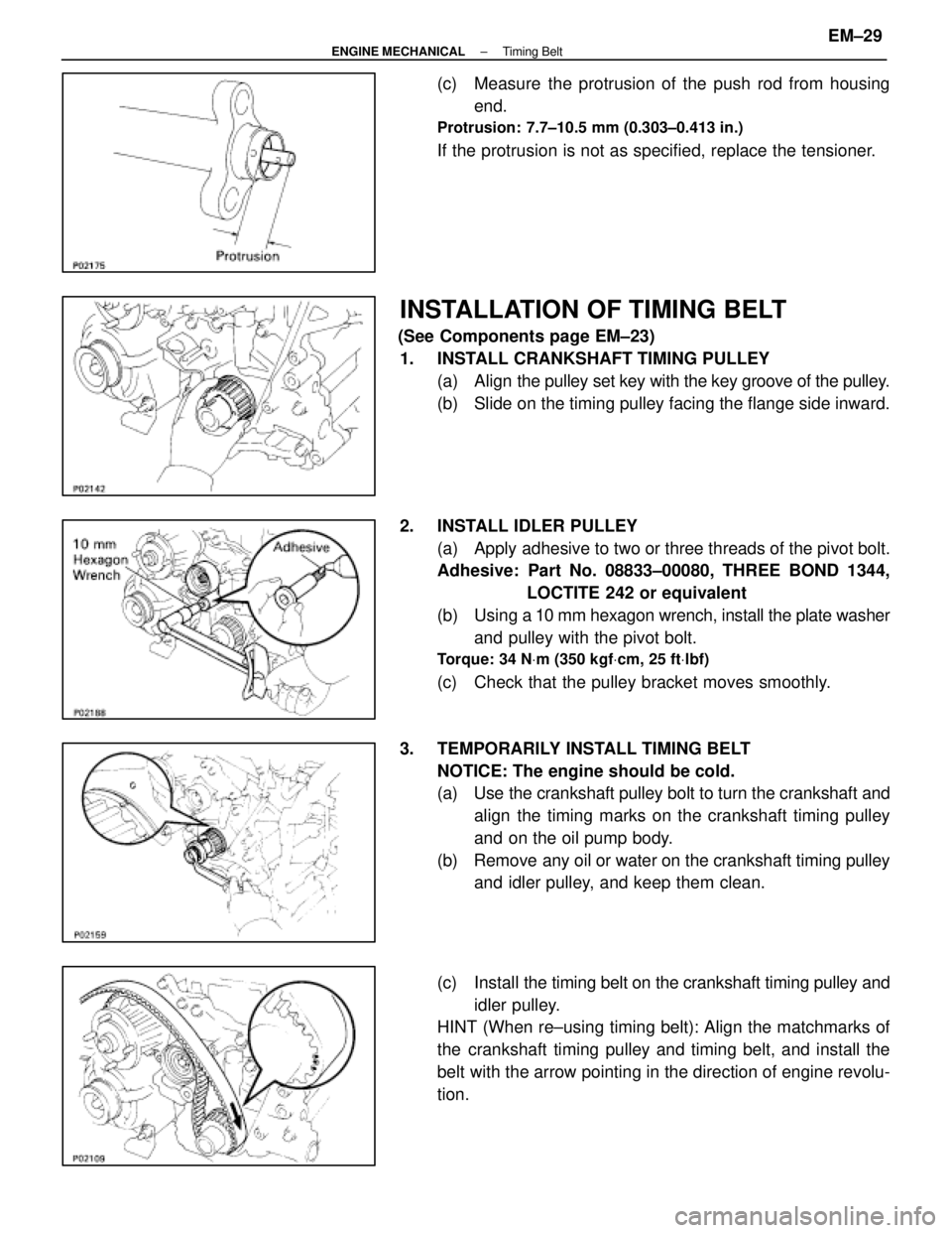
(c) Measure the protrusion of the push rod from housingend.
Protrusion: 7.7±10.5 mm (0.303±0.413 in.)
If the protrusion is not as specified, replace the tensioner.
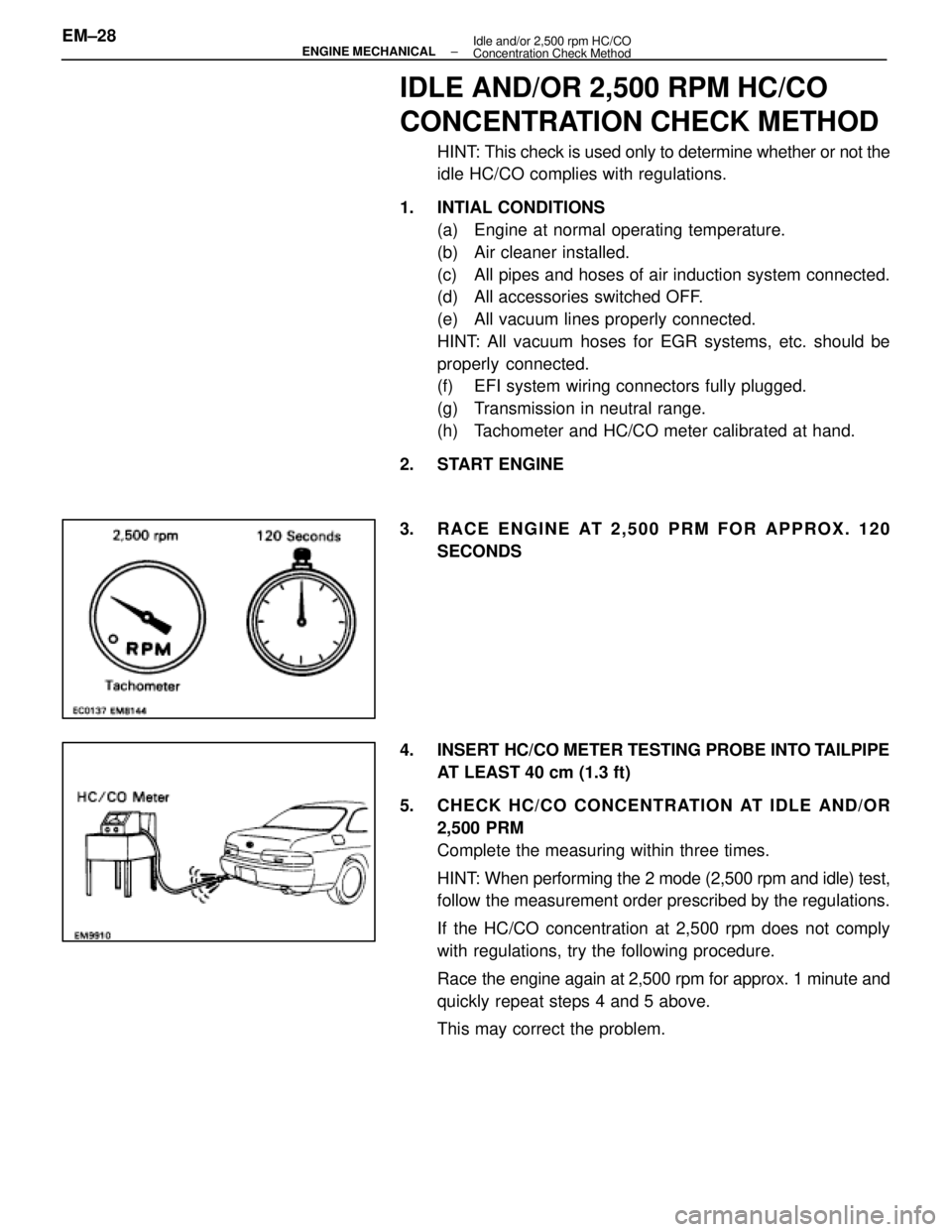
INSTALLATION OF TIMING BELT
(See Components page EM±23)1. INSTALL CRANKSHAFT TIMING PULLEY (a) Align the pulley set key with the key groove of the pulley.
(b) Slide on the timing pulley facing the flange side inward.
2. INSTALL IDLER PULLEY (a) Apply adhesive to two or three threads of the pivot bolt.
Adhesive: Part No. 08833±00080, THREE BOND 1344, LOCTITE 242 or equivalent
(b) Using a 10 mm hexagon wrench, install the plate washer
and pulley with the pivot bolt.
Torque: 34 N Vm (350 kgf Vcm, 25 ft Vlbf)
(c) Check that the pulley bracket moves smoothly.
3. TEMPORARILY INSTALL TIMING BELT NOTICE: The engine should be cold.
(a) Use the crankshaft pulley bolt to turn the crankshaft andalign the timing marks on the crankshaft timing pulley
and on the oil pump body.
(b) Remove any oil or water on the crankshaft timing pulley and idler pulley, and keep them clean.
(c) Install the timing belt on the crankshaft timing pulley and
idler pulley.
HINT (When re±using timing belt): Align the matchmarks of
the crankshaft timing pulley and timing belt, and install the
belt with the arrow pointing in the direction of engine revolu-
tion.
±
ENGINE MECHANICAL Timing BeltEM±29
WhereEverybodyKnowsYourName
Page 1697 of 4087
4. INSTALL TIMING BELT GUIDEInstall the guide, facing the cup side outward.
5. INSTALL NO. 1 TIMING BELT COVER (a) Install the two gaskets to the timing belt cover.
(b) Install the timing belt cover with the five bolts.
6. INSTALL CRANKSHAFT PULLEY (a) Align the pulley set key with the key groove of the pulley,
and slide on the pulley.
(b) Using SST, install and torque the bolt.
SST 09213±54015 (09651±60855) and 09330±00021
Torque: 324 N Vm (3,300 kgf Vcm, 239 ft Vlbf)
7. INSTALL CAMSHAFT TIMING PULLEYS
(a) Align the camshaft knock pin with the groove on thepulley, and slide on the timing pulley.
(b) Using SST to hold the pulley, torque the pulley bolt.
SST 09278±54012
Torque: 79 N Vm (810 kgf Vcm, 59 ft Vlbf)
8. SET NO. 1 CYLINDER TO TDC/COMPRESSION
(a) Turn the crankshaft pulley, and align its groove withtiming mark º0º of the No. 1 timing belt cover.
EM±30
±
ENGINE MECHANICAL Timing Belt
WhereEverybodyKnowsYourName
Page 1698 of 4087
(b) Turn the camshaft, and align the timing marks of thecamshaft timing pulleys and No. 4 timing belt cover.
SST 09278±54012
9. INSTALL TIMING BELT HINT (When re±using timing belt): Align the matchmarks of
the timing belt and camshaft timing pulleys.
(a) Remove any oil or water on the camshaft timing pulley,and keep it clean.
(b) Install the timing belt, checking the tension between the
crankshaft timing pulley and exhaust camshaft timing
pulley.
10. SET TIMING BELT TENSIONER (a) Using a press, slowly press in the push rod using981±9,807N (100±1,000 kgf, 220±2,205 lbf) of
pressure.
(b) Align the holes of the push rod and housing, pass a 1.50
mm hexagon wrench through the holes to keep the push
rod retracted.
(c) Release the press.
(d) Install the dust boot onto the tensioner.
±
ENGINE MECHANICAL Timing BeltEM±31
WhereEverybodyKnowsYourName
Page 1699 of 4087
11. INSTALL TIMING BELT TENSIONER(a) Temporarily install the tensioner with the two bolts.
(b) Alternately tighten the two bolts.
Torque: 26 N Vm (270 kgf Vcm, 20 ft Vlbf)
(c) R e m o v e t h e 1 . 5 0 m m h e x agon wrench from the
tensioner with pliers.
12. CHECK VALVE TIMING (a) Turn the crankshaft pulley two revolutions from TDC toTDC.
NOTICE: Always turn the crankshaft clockwise.
(b) Check that each pulley aligns with the timing marks as shown in the figure.
If the marks do not align, remove the timing belt and reinstall
it.
13. INSTALL DRIVE BELT TENSIONER Install the tensioner with the three bolts.
Torque: 21 N Vm (210 kgf Vcm, 15 ft Vlbf)
NOTICE: Be careful not to drop the bolts inside the timing
belt cover.
EM±32
±
ENGINE MECHANICAL REPAIR INSTRUCTIONS
WhereEverybodyKnowsYourName
Page 1700 of 4087
14. INSTALL NO. 2 AND NO. 3 TIMING BELT COVERS(a) Install the gasket on the timing belt cover.
(b) Using a 5 mm hexagon wrench, install the belt coverswith the nine bolts.
(c) Install the oil filler cap.
15. INSTALL RADIATOR AND WATER PUMP PULLEY (See steps 15, 16, 19 and 24 on pages EM±110 to 112)
16. FILL ENGINE WITH COOLANT (See page CO±5)
Capacity (w/ Heater):
M/T 8.5 liters (9.0 US qts, 7.5 Imp. qts)
A/T 8.4 liters (8.9 US qts, 7.4 Imp. qts)
17. (A/T)CHECK AUTOMATIC TRANSMISSION FLUID LEVEL
(See page MA±11)
NOTICE: Do not overfill.
18. START ENGINE AND CHECK FOR LEAKS
19. CHECK IGNITION TIMING (See page IG±14)
Ignition timing:
105 BTDC @ idle
(w/ Terminals TE1 and E1 connected)
20. PERFORM ROAD TEST Check for abnormal noise, shock, slippage, correct shift
points and smooth operation.
21. RECHECK ENGINE COOLANT LEVEL
±
ENGINE MECHANICAL Timing BeltEM±33
WhereEverybodyKnowsYourName
Page 1701 of 4087

IDLE AND/OR 2,500 RPM HC/CO
CONCENTRATION CHECK METHOD
HINT: This check is used only to determine whether or not the
idle HC/CO complies with regulations.
1. INTIAL CONDITIONS (a) Engine at normal operating temperature.
(b) Air cleaner installed.
(c) All pipes and hoses of air induction system connected.
(d) All accessories switched OFF.
(e) All vacuum lines properly connected.
HINT: All vacuum hoses for EGR systems, etc. should be
properly connected.
(f) EFI system wiring connectors fully plugged.
(g) Transmission in neutral range.
(h) Tachometer and HC/CO meter calibrated at hand.
2. START ENGINE
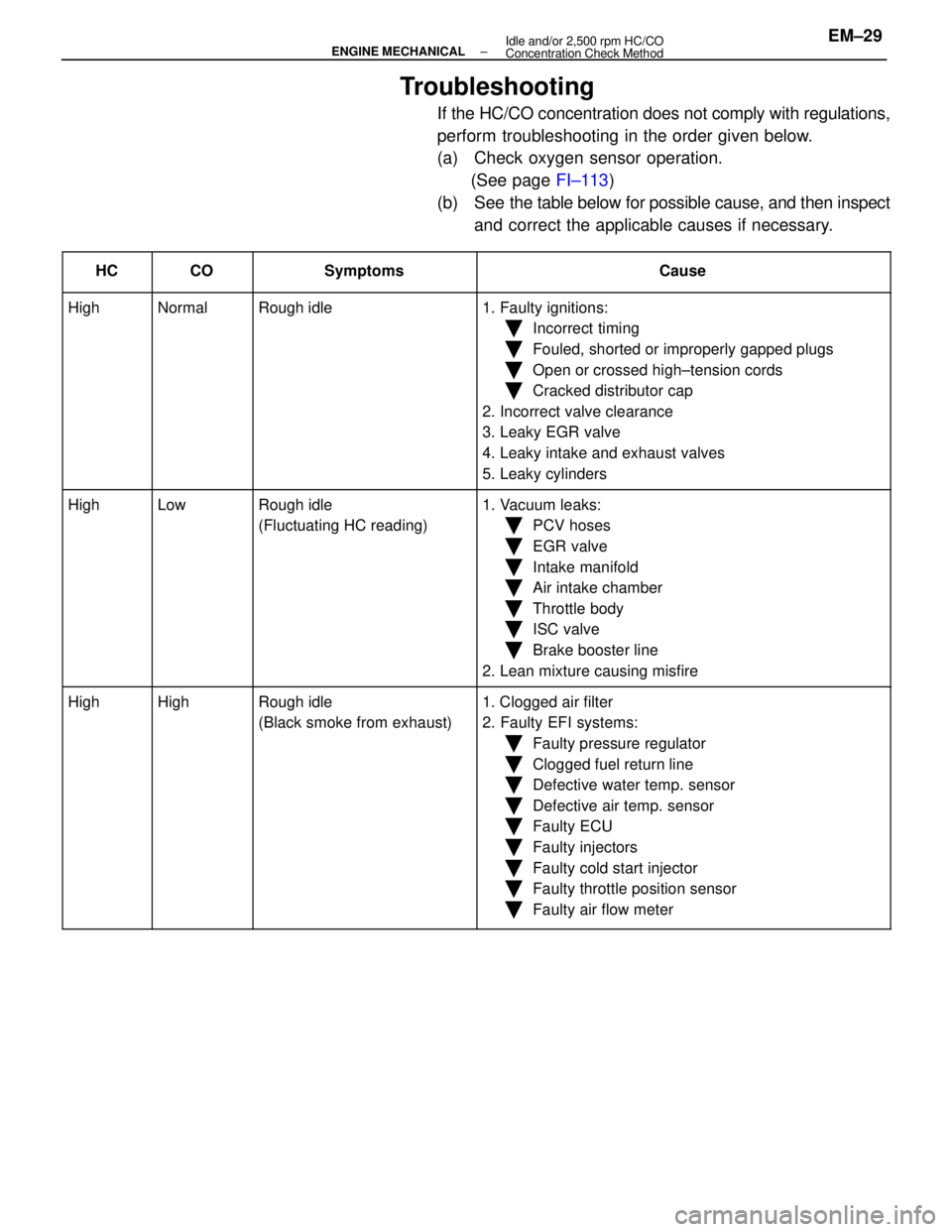
3. RACE ENGINE AT 2,500 PRM FOR APPROX. 120 SECONDS
4. INSERT HC/CO METER TESTING PROBE INTO TAILPIPE AT LEAST 40 cm (1.3 ft)
5. CHECK HC/CO CONCENTRATION AT IDLE AND/OR 2,500 PRM
Complete the measuring within three times.
HINT: When performing the 2 mode (2,500 rpm and idle) test,
follow the measurement order prescribed by the regulations.
If the HC/CO concentration at 2,500 rpm does not comply
with regulations, try the following procedure.
Race the engine again at 2,500 rpm for approx. 1 minute and
quickly repeat steps 4 and 5 above.
This may correct the problem.
EM±28
±
ENGINE MECHANICAL Idle and/or 2,500 rpm HC/CO
Concentration Check Method
WhereEverybodyKnowsYourName
Page 1702 of 4087

Troubleshooting
If the HC/CO concentration does not comply with regulations,
perform troubleshooting in the order given below.
(a) Check oxygen sensor operation.(See page FI±113)
(b) See the table below for possible cause, and then inspect
and correct the applicable causes if necessary.
����� �
����
�����HC����� �
����
�����CO���������� �
���������
����������Symptoms������������������\
� �
������������������
������������������\
�Cause
����� �����High����� �����Normal���������� ����������Rough idle������������������\
� ������������������\
�1. Faulty ignitions:
����� ���������� ��������������� ����������������������������\
� ������������������\
��Incorrect timing
����� ���������� ��������������� ����������������������������\
� ������������������\
��Fouled, shorted or improperly gapped plugs
����� ���������� ��������������� ����������������������������\
� ������������������\
��Open or crossed high±tension cords
Ckddiib��������������������������������������\
��Cracked distributor cap
Ill����� ���������� ��������������� ����������������������������\
� ������������������\
�2. Incorrect valve clearance
3 L k EGR l����� ���������� ��������������� ����������������������������\
� ������������������\
�3. Leaky EGR valve
4L k i k d h l����� ���������� ��������������� ����������������������������\
� ������������������\
�4. Leaky intake and exhaust valves
L k li d����� ���������� ��������������� ����������������������������\
� ������������������\
�5. Leaky cylinders
����� �����High����� �����Low���������� ����������Rough idle������������������\
� ������������������\
�1. Vacuum leaks:
����� ���������� ��������������� ����������(Fluctuating HC reading)������������������\
� ������������������\
��PCV hoses
����� ���������� ��������������� ����������������������������\
� ������������������\
��EGR valve
����� ���������� ��������������� ����������������������������\
� ������������������\
��Intake manifold
Ai i k h b����� ���������� ��������������� ����������������������������\
� ������������������\
��Air intake chamber
Th l b d����� ���������� ��������������� ����������������������������\
� ������������������\
��Throttle body
ISC l��������������������������������������\
��ISC valve
Bkb li����� ���������� ��������������� ����������������������������\
� ������������������\
��Brake booster line
2L i i ifi����� ���������� ��������������� ����������������������������\
� ������������������\
�2. Lean mixture causing misfire
����� �����High����� �����High���������� ����������Rough idle������������������\
� ������������������\
�1. Clogged air filter����� �����g����� �����g���������� ����������g
(Black smoke from exhaust)������������������\
� ������������������\
�gg
2. Faulty EFI systems:����� ���������� ��������������� ����������()������������������\
� ������������������\
�yy
�Faulty pressure regulator
����� ���������� ��������������� ����������������������������\
� ������������������\
�
yg
�Clogged fuel return line
����� ���������� ��������������� ����������������������������\
� ������������������\
�
gg
�Defective water temp. sensor
����� ���������� ��������������� ����������������������������\
� ������������������\
��Defective air temp. sensor
����� ���������� ��������������� ����������������������������\
� ������������������\
��Faulty ECU
����� ���������� ��������������� ����������������������������\
� ������������������\
�
y
�Faulty injectors
��������������������������������������\
�
yj
�Faulty cold start injector����� ���������� ��������������� ����������������������������\
� ������������������\
�yj
�Faulty throttle position sensor����� ���������� ��������������� ����������������������������\
� ������������������\
��Faulty air flow meter
±
ENGINE MECHANICAL Idle and/or 2,500 rpm HC/CO
Concentration Check MethodEM±29
WhereEverybodyKnowsYourName
Page 1703 of 4087
COMPRESSION CHECK
HINT: If there is lack of power, excessive oil consumption or
poor fuel economy, measure the compression pressure.
1. WARM UP AND STOP ENGINE Allow the engine to warm up to normal operating tempera-
ture.
2. REMOVE NO.3 TIMING BELT COVERS (See steps 1, 5 to 10 and 14 on pages EM±11 to 13)
3. DISCONNECT COLD START INJECTOR CONNECTOR
4. DISCONNECT RH CAM POSITION SENSOR CONNECTOR
(a) Disconnect the connector from the ignition coil bracket.
(b) Disconnect the sensor connector.
5. DISCONNECT LH CAM POSITION SENSOR CONNECTOR
6. REMOVE SPARK PLUGS (a) Disconnect the eight high±tension cords from the sparkplugs.
Disconnect the high±tension cords at rubber boot. Do
not pull on the cords.
NOTICE: Pulling on or bending the cords may damage
the conductor inside.
EM±30
±
ENGINE MECHANICAL Compression Check
WhereEverybodyKnowsYourName