Page 3743 of 4087
CIRCUIT DESCRIPTION (Cont'd)
DIAGNOSIS CODE DETECTION DRIVING PATTERN
Purpose of the driving pattern.
(a) To simulate diag. code detecting condition after diag. code is recorded.
(b) To check that the malfunction is corrected when the repair is completed c\
onfirming that diag. code is nolonger detected.
�Initiate test mode (See page TR±12).
�Start engine and warm up.
�After engine is warmed up, let it idle for 3 min.
�With the A/C ON and transmission in D range (O/D OFF), drive at 40±\
70 mph for 4 min.
HINT: If a malfunction exists, the ºCHECKº engine warning light will light up at 1±4 min. of driving at 40±70 mph (64±112 km/h).
NOTICE: If the conditions in this test are not strictly followed, detection of the\
malfunction will not be possible.
Malfunction: Open in EGR gas temp. sensor circuit
±
ENGINE TROUBLESHOOTING Circuit InspectionTR±109
WhereEverybodyKnowsYourName
Page 3748 of 4087

WIRING DIAGRAM
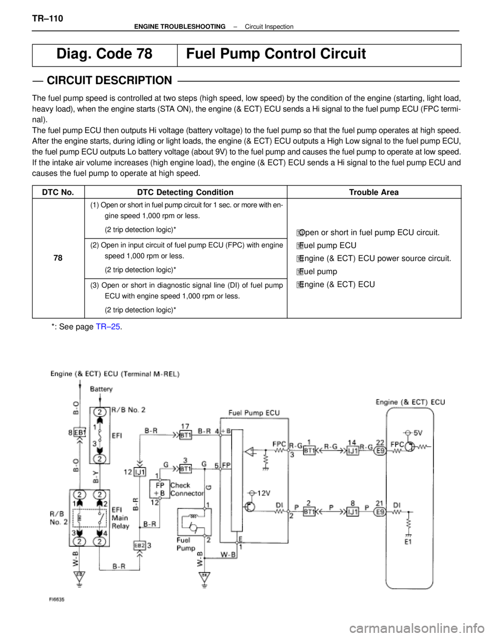
Diag. Code 78Fuel Pump Control Circuit
CIRCUIT DESCRIPTION
The fuel pump speed is controlled at two steps (high speed, low speed) by\
the condition of the engine (starting, light load,
heavy load), when the engine starts (STA ON), the engine (& ECT) ECU sends a Hi signal to the fuel pump ECU \
(FPC termi-
nal).
The fuel pump ECU then outputs Hi voltage (battery voltage) to the fue\
l pump so that the fuel pump operates at high speed.
After the engine starts, during idling or light loads, the engine (& ECT) EC\
U outputs a High Low signal to the fuel pump ECU,
the fuel pump ECU outputs Lo battery voltage (about 9V) to the fuel pu\
mp and causes the fuel pump to operate at low speed.
If the intake air volume increases (high engine load), the engine (& EC\
T) ECU sends a Hi signal to the fuel pump ECU and
causes the fuel pump to operate at high speed.
DTC No.
DTC Detecting ConditionTrouble Area
(1) Open or short in fuel pump circuit for 1 sec. or more with en- gine speed 1,000 rpm or less.
(2 trip detection logic)*
�Open or short in fuel pump ECU circuit.
78
(2) Open in input circuit of fuel pump ECU (FPC) with engine
speed 1,000 rpm or less.
(2 trip detection logic)*�Fuel pump ECU
� Engine (& ECT) ECU power source circuit.
� Fuel pump
(3) Open or short in diagnostic signal line (DI) of fuel pump
ECU with engine speed 1,000 rpm or less.
(2 trip detection logic)*�Engine (& ECT) ECU
*: See page TR±25.
TR±110±
ENGINE TROUBLESHOOTING Circuit Inspection
WhereEverybodyKnowsYourName
Page 3752 of 4087

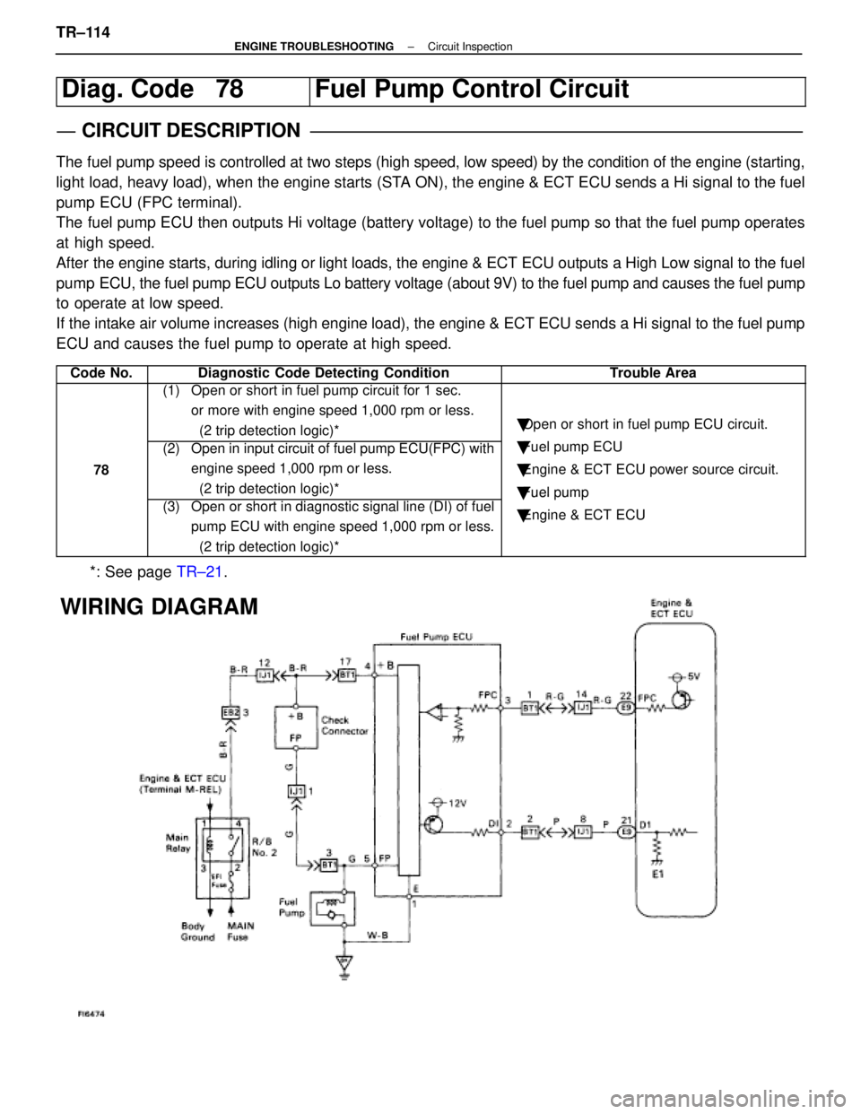
Diag. Code 78Fuel Pump Control Circuit
CIRCUIT DESCRIPTION
The fuel pump speed is controlled at two steps (high speed, low speed) by\
the condition of the engine (starting,
light load, heavy load), when the engine starts (STA ON), the engine & ECT ECU sends a Hi signal to the fuel
pump ECU (FPC terminal).
The fuel pump ECU then outputs Hi voltage (battery voltage) to the fuel p\
ump so that the fuel pump operates
at high speed.
After the engine starts, during idling or light loads, the engine & ECT ECU o\
utputs a High Low signal to the fuel
pump ECU, the fuel pump ECU outputs Lo battery voltage (about 9V) to the f\
uel pump and causes the fuel pump
to operate at low speed.
If the intake air volume increases (high engine load), the engine & ECT \
ECU sends a Hi signal to the fuel pump
ECU and causes the fuel pump to operate at high speed.
Code No.Diagnostic Code Detecting ConditionTrouble Area
(1) Open or short in fuel pump circuit for 1 sec. or more with engine speed 1,000 rpm or less.
(2 trip detection logic)*
�Open or short in fuel pump ECU circuit.
78
(2) Open in input circuit of fuel pump ECU(FPC) with
engine speed 1,000 rpm or less.
(2 trip detection logic)*�Fuel pump ECU
� Engine & ECT ECU power source circuit.
� Fuel pump
(3) Open or short in diagnostic signal line (DI) of fuel
pump ECU with engine speed 1,000 rpm or less.
(2 trip detection logic)*
�Fuel um
�Engine & ECT ECU
*: See page TR±21.
WIRING DIAGRAM
TR±114±
ENGINE TROUBLESHOOTING Circuit Inspection
WhereEverybodyKnowsYourName
Page 3758 of 4087

OKNG
OKNG
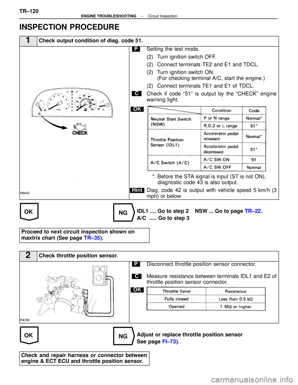
INSPECTION PROCEDURE
1Check output condition of diag. code 51.
C
OK
Hint
PSetting the test mode.
(2) Turn ignition switch OFF.
(2) Connect terminals TE2 and E1 and TDCL.
(2) Turn ignition switch ON.(For checking terminal A/C, start the engine.)
(2) Connect terminals TE1 and E1 of TDCL.
Check if code ª51º is output by the ªCHECKº engine
warning light.
*: Before the STA signal is input (ST is not ON), diagnostic code 43 is also output.
Diag. code 42 is output with vehicle speed 5 km/h (3
mph) or below
IDL1 .... Go to step 2 NSW ... Go to page TR±22.
A/C ..... Go to step 3
Proceed to next circuit inspection shown on
maxtrix chart (See page TR±35).
2Check throttle position sensor.
C
OK
PDisconnect throttle position sensor connector.
Measure resistance between terminals IDL1 and E2 of
throttle position sensor connector.
Adjust or replace throttle position sensor
See page FI±73).
Check and repair harness or connector between
engine & ECT ECU and throttle position sensor.
TR±120±
ENGINE TROUBLESHOOTING Circuit Inspection
WhereEverybodyKnowsYourName
Page 3771 of 4087

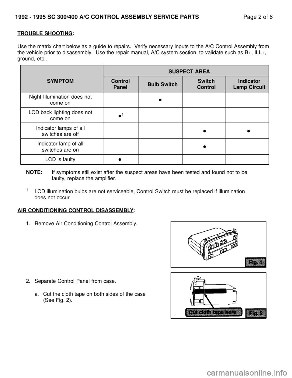
TROUBLE SHOOTING:
Use the matrix chart below as a guide to repairs. Verify necessary inputs to the A/C Control Assembly from
the vehicle prior to disassembly. Use the repair manual, A/C system section, to validate such as B+, IL\
L+,
ground, etc.. SUSPECT AREA
SYMPTOM Control Switch Indicator Panel Control Lamp Circuit
Night Illumination does not come on
LCD back lighting does not come on
Indicator lamps of all switches are off
Indicator lamp of all switches are on
LCD is faulty
NOTE: If symptoms still exist after the suspect areas have been tested and fou\
nd not to be
faulty, replace the amplifier.
1LCD illumination bulbs are not serviceable, Control Switch must be repla\
ced if illumination
does not occur.
AIR CONDITIONING CONTROL DISASSEMBLY
:
1. Remove Air Conditioning Control Assembly.
2. Separate Control Panel from case. a. Cut the cloth tape on both sides of the case (See Fig. 2).
1992 - 1995 SC 300/400 A/C CONTROL ASSEMBLY SERVICE PARTS Page 2 of 6
Bulb Switch
�
�
1
�
�
�
�
WhereEverybodyKnowsYourName
Page 3788 of 4087
SENSOR INSPECTION FOR AIR CONDITIONING SYSTEM ± AC005-04 December 16, 2004
Page 2 of 12
1. Inspect Room Temperature Sensor.
A. Measure the sensor resistance.
Resistance Value at 77 5F
(25 5C)1700 +/± 85 W
NOTE:
�Even slightly touching the sensor
may change the resistance value.
Be sure to hold the connector of
the sensor.
� When measuring, the sensor
temperature must be the same as
the ambient temperature.
HINT:
As the temperature increases, the
resistance decreases.
TEMPERATURE 5F ( 5C)SPECIFICATION k W
50 (10)3.00 to 3.73
59 (15)2.45 to 2.88
68 (20)1.95 to 2.30
77 (25)1.60 to 1.80
86 (30)1.28 to 1.47
95 (35)1.00 to 1.22
104 (40)0.80 to 1.00
113 (45)0.65 to 0.85
122 (50)0.50 to 0.70
131 (55)0.44 to 0.60
140 (60)0.36 to 0.50
Inspection
Procedure
Resistance
k W
4.0
3.5
3.0
2.5
2.0
1.5
1.0
0.5
0.0
32
(0) 68
(20) 104
(40) 140
(60)
Temperature 5F ( 5C)
Max
Min
WhereEverybodyKnowsYourName
Page 3789 of 4087
SENSOR INSPECTION FOR AIR CONDITIONING SYSTEM ± AC005-04 December 16, 2004
Page 3 of 12
2. Inspect Ambient
Temperature Sensor.
A. Measure the sensor resistance according to the selected graph
(specification).
Resistance Value at 77 5F
(25 5C)1700 +/± 85 W
NOTE:
�Even slightly touching the sensor
may change the resistance value.
Be sure to hold the connector of
the sensor.
� When measuring, the sensor
temperature must be the same as
the ambient temperature.
HINT:
As the temperature increases, the
resistance decreases.
TEMPERATURE 5F ( 5C)SPECIFICATION k W
50 (10)3.00 to 3.73
59 (15)2.45 to 2.88
68 (20)1.95 to 2.30
77 (25)1.60 to 1.80
86 (30)1.28 to 1.47
95 (35)1.00 to 1.22
104 (40)0.80 to 1.00
113 (45)0.65 to 0.85
122 (50)0.50 to 0.70
131 (55)0.44 to 0.60
140 (60)0.36 to 0.50
Inspection
Procedure
(Continued)
Resistance
k W
4.0
3.5
3.0
2.5
2.0
1.5
1.0
0.5
0.0
32
(0) 68
(20) 104
(40) 140
(60)
Temperature 5F ( 5C)
Max
Min
WhereEverybodyKnowsYourName
Page 3790 of 4087
SENSOR INSPECTION FOR AIR CONDITIONING SYSTEM ± AC005-04 December 16, 2004
Page 4 of 12
3. Inspect Air Duct Sensor.
A. Measure the sensor resistanceaccording to the table and
graph (specification).
NOTE:
�Even slightly touching the sensor
may change the resistance value.
Be sure to hold the connector of
the sensor.
� When measuring, the sensor
temperature must be the same as
the ambient temperature.
HINT:
As the temperature increases, the
resistance decreases.
TEMPERATURE 5F ( 5C)SPECIFICATION k W
50 (10)9.48 to 10.49
59 (15)7.50 to 8.28
68 (20)5.95 to 6.57
77 (25)4.77 to 5.25
86 (30)3.85 to 4.21
95 (35)3.12 to 3.40
104 (40)2.53 to 2.79
113 (45)2.06 to 2.30
122 (50)1.69 to 1.91
131 (55)1.39 to 1.59
140 (60)1.15 to 1.33
Inspection
Procedure
(Continued)
Resistance
k W
15.0
10.0
5.0
0.0 32
(0) 68
(20) 104
(40) 140
(60)
Temperature 5F ( 5C)
Max
Min 176
(80)
WhereEverybodyKnowsYourName