Page 3496 of 4087
CIRCUIT DESCRIPTION (Cont'd)
DIAGNOSIS CODE DETECTION DRIVING PATTERN
Purpose of the driving pattern.
(a) To simulate diag. code detecting condition after diag. code is recorded.
(b) To check that the malfunction is corrected when the repair is completed co\
nfirming that diag. codeis no longer detected.
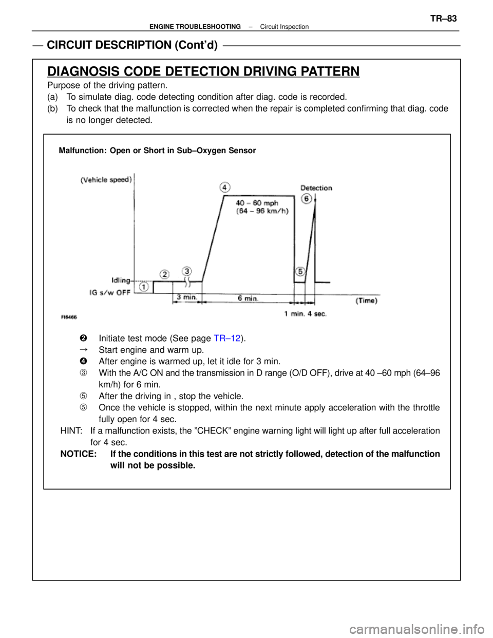
Malfunction: Open or Short in Sub±Oxygen Sensor
�Initiate test mode (See page TR±12).
�Start engine and warm up.
�After engine is warmed up, let it idle for 3 min.
�With the A/C ON and the transmission in D range (O/D OFF), drive at 40 ±\
60 mph (64±96
km/h) for 6 min.
�After the driving in , stop the vehicle.
�Once the vehicle is stopped, within the next minute apply acceleration w\
ith the throttle
fully open for 4 sec.
HINT: If a malfunction exists, the ºCHECKº engine warning light will light\
up after full acceleration for 4 sec.
NOTICE: If the conditions in this test are not strictly followed, detection of the\
malfunction will not be possible.
±
ENGINE TROUBLESHOOTING Circuit InspectionTR±83
WhereEverybodyKnowsYourName
Page 3502 of 4087
Diag. Code 31Air Flow Meter Circuit
CIRCUIT DESCRIPTION
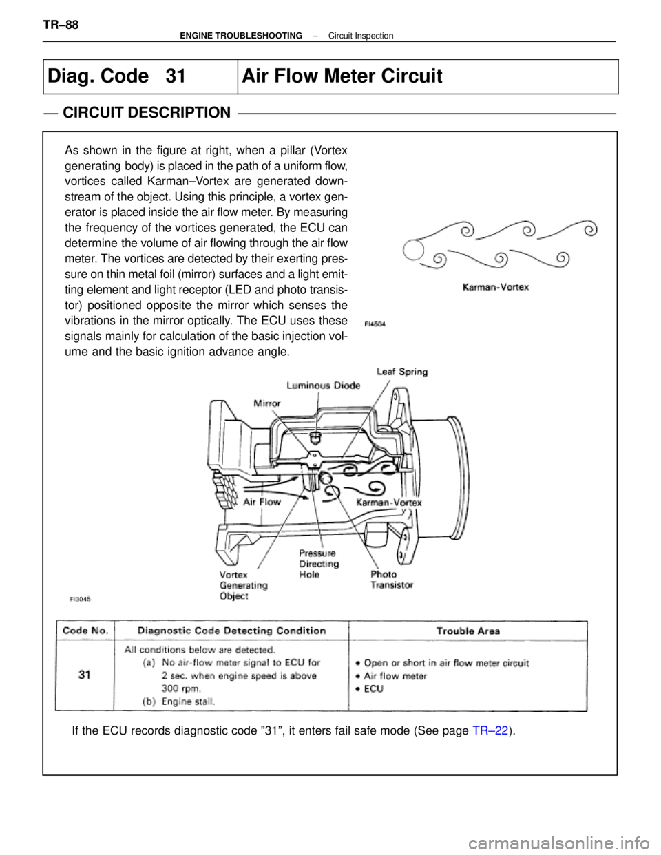
As shown in the figure at right, when a pillar (Vortex
generating body) is placed in the path of a uniform flow,
vortices called Karman±Vortex are generated down-
stream of the object. Using this principle, a vortex gen-
erator is placed inside the air flow meter. By measuring
the frequency of the vortices generated, the ECU can
determine the volume of air flowing through the air flow
meter. The vortices are detected by their exerting pres-
sure on thin metal foil (mirror) surfaces and a light emit-
ting element and light receptor (LED and photo transis-
tor) positioned opposite the mirror which senses the
vibrations in the mirror optically. The ECU uses these
signals mainly for calculation of the basic injection vol-
ume and the basic ignition advance angle.
If the ECU records diagnostic code º31º, it enters fail safe mode \
(See page TR±22).
TR±88
±
ENGINE TROUBLESHOOTING Circuit Inspection
WhereEverybodyKnowsYourName
Page 3525 of 4087
CIRCUIT DESCRIPTION (Cont'd)
DIAGNOSIS TROUBLE CODE DETECTION DRIVING PATTERN
Purpose of the driving pattern.
(a) To simulate diag. trouble code detecting condition after diag. trouble co\
de is recorded.
(b) To check that the malfunction is corrected when the repair is completed co\
nfirming that diag. trouble codeis no longer detected.
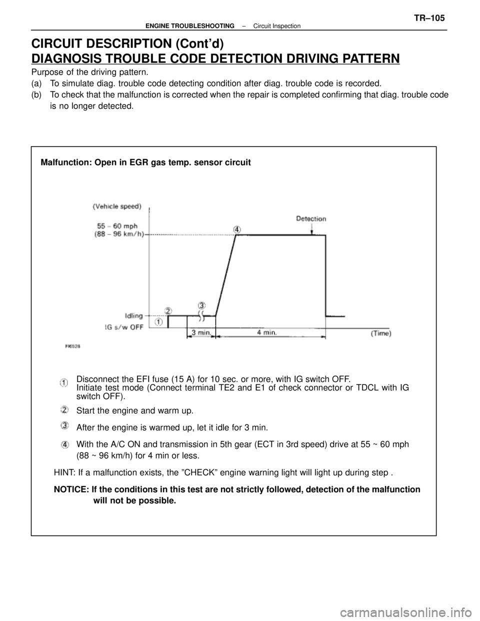
Malfunction: Open in EGR gas temp. sensor circuit
Disconnect the EFI fuse (15 A) for 10 sec. or more, with IG switch OFF\
.
Initiate test mode (Connect terminal TE2 and E1 of check connector or TDCL with\
IG
switch OFF).
Start the engine and warm up.
After the engine is warmed up, let it idle for 3 min.
With the A/C ON and transmission in 5th gear (ECT in 3rd speed) drive at 5\
5 ~ 60 mph
(88 ~ 96 km/h) for 4 min or less.
HINT: If a malfunction exists, the ºCHECKº engine warning light will l\
ight up during step .
NOTICE: If the conditions in this test are not strictly followed, detection of \
the malfunction will not be possible.
±
ENGINE TROUBLESHOOTING Circuit InspectionTR±105
WhereEverybodyKnowsYourName
Page 3531 of 4087
CIRCUIT DESCRIPTION (Cont'd)
DIAGNOSIS CODE DETECTION DRIVING PATTERN
Purpose of the driving pattern.
(a) To simulate diag. code detecting condition after diag. code is recorded.
(b) To check that the malfunction is corrected when the repair is completed c\
onfirming that diag. code is nolonger detected.
�Initiate test mode (See page TR±12).
�Start engine and warm up.
�After engine is warmed up, let it idle for 3 min.
�With the A/C ON and transmission in D range (O/D OFF), drive at 40±\
70 mph for 4 min.
HINT: If a malfunction exists, the ºCHECKº engine warning light will light up at 1±4 min. of driving at 40±70 mph (64±112 km/h).
NOTICE: If the conditions in this test are not strictly followed, detection of the\
malfunction will not be possible.
Malfunction: Open in EGR gas temp. sensor circuit
±
ENGINE TROUBLESHOOTING Circuit InspectionTR±109
WhereEverybodyKnowsYourName
Page 3554 of 4087
Neutral Start Switch Circuit
CIRCUIT DESCRIPTION
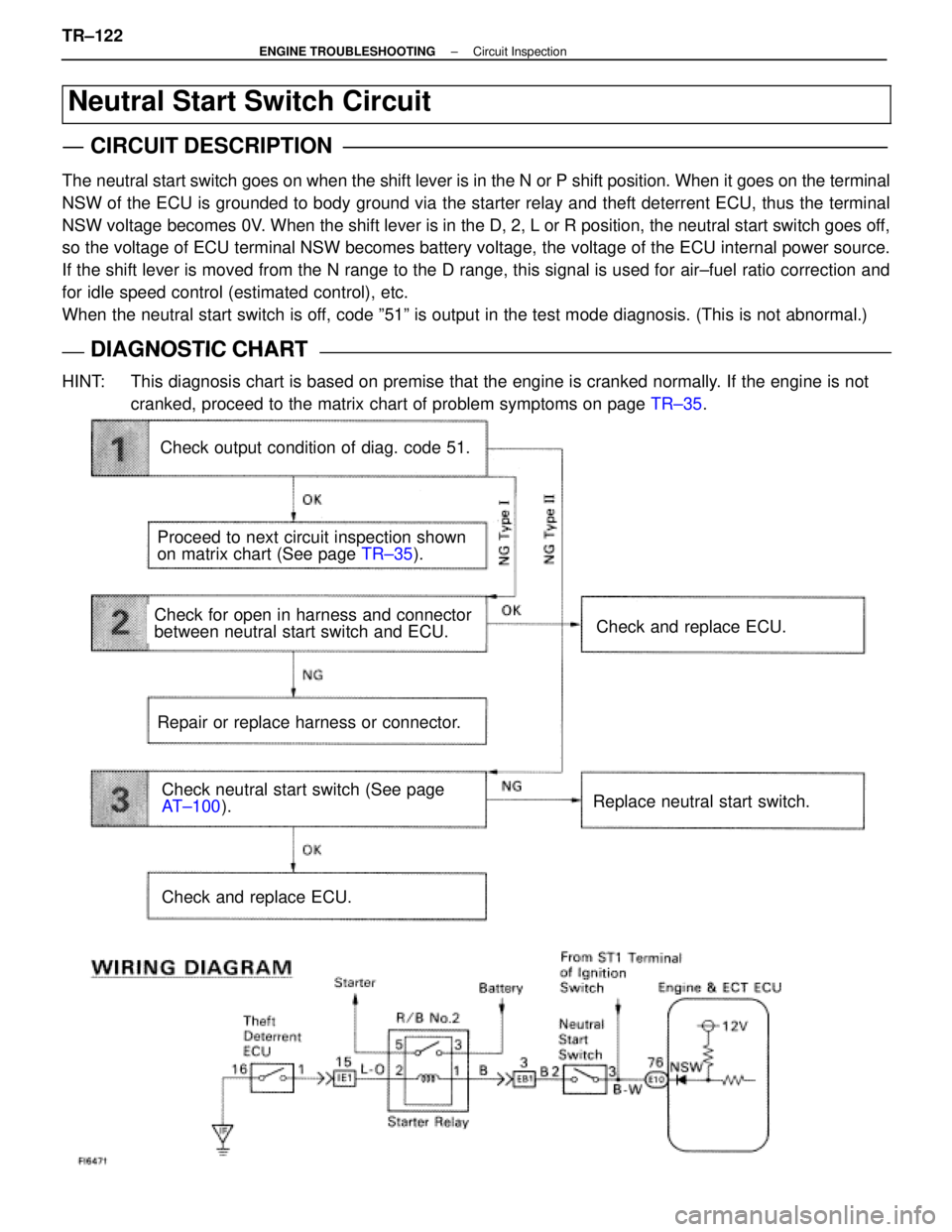
The neutral start switch goes on when the shift lever is in the N or P shif\
t position. When it goes on the terminal
NSW of the ECU is grounded to body ground via the starter relay and theft deterrent ECU\
, thus the terminal
NSW voltage becomes 0V. When the shift lever is in the D, 2, L or R position, the neutral start\
switch goes off,
so the voltage of ECU terminal NSW becomes battery voltage, the voltage of the ECU internal power source.
If the shift lever is moved from the N range to the D range, this signal\
is used for air±fuel ratio correction and
for idle speed control (estimated control), etc.
When the neutral start switch is off, code º51º is output in the test mode diagnosis. (This is not a\
bnormal.)
DIAGNOSTIC CHARTDIAGNOSTIC CHART
HINT: This diagnosis chart is based on premise that the engine is cranked norm\
ally. If the engine is notcranked, proceed to the matrix chart of problem symptoms on page TR±35.
Check output condition of diag. code 51.
Proceed to next circuit inspection shown
on matrix chart (See page TR±35).
Check for open in harness and connector
between neutral start switch and ECU.
Repair or replace harness or connector.
Check and replace ECU.
Check and replace ECU.
Replace neutral start switch.Check neutral start switch (See page
AT±100 ).
TR±122
±
ENGINE TROUBLESHOOTING Circuit Inspection
WhereEverybodyKnowsYourName
Page 3605 of 4087
DIAGNOSTIC CODE CHART (Cont'd)
*1: ºONº displayed in the diagnosis mode column indicates that the º\
CHECKº Engine Warning Light islighted up when a malfunction is detected. ºOFFº indicates that the ºC\
HECKº does not light up during
malfunction diagnosis, even if a malfunction is detected. ºN.A.º i\
ndicates that the item is not included
in malfunction diagnosis.
*2: ºOº in the memory column indicates that a diagnostic code is reco\
rded in the ECU memory when a mal- function occurs. ºXº indicates that a diagnostic code is not recor\
ded in the ECU memory even if a mal-
function occurs. Accordingly, output of diagnostic results in normal or test mode is performed with \
the
IG switch ON.
*3: Only for USA specification vehicles.
TR±20
±
ENGINE TROUBLESHOOTING Diagnostic Code Chart
WhereEverybodyKnowsYourName
Page 3606 of 4087
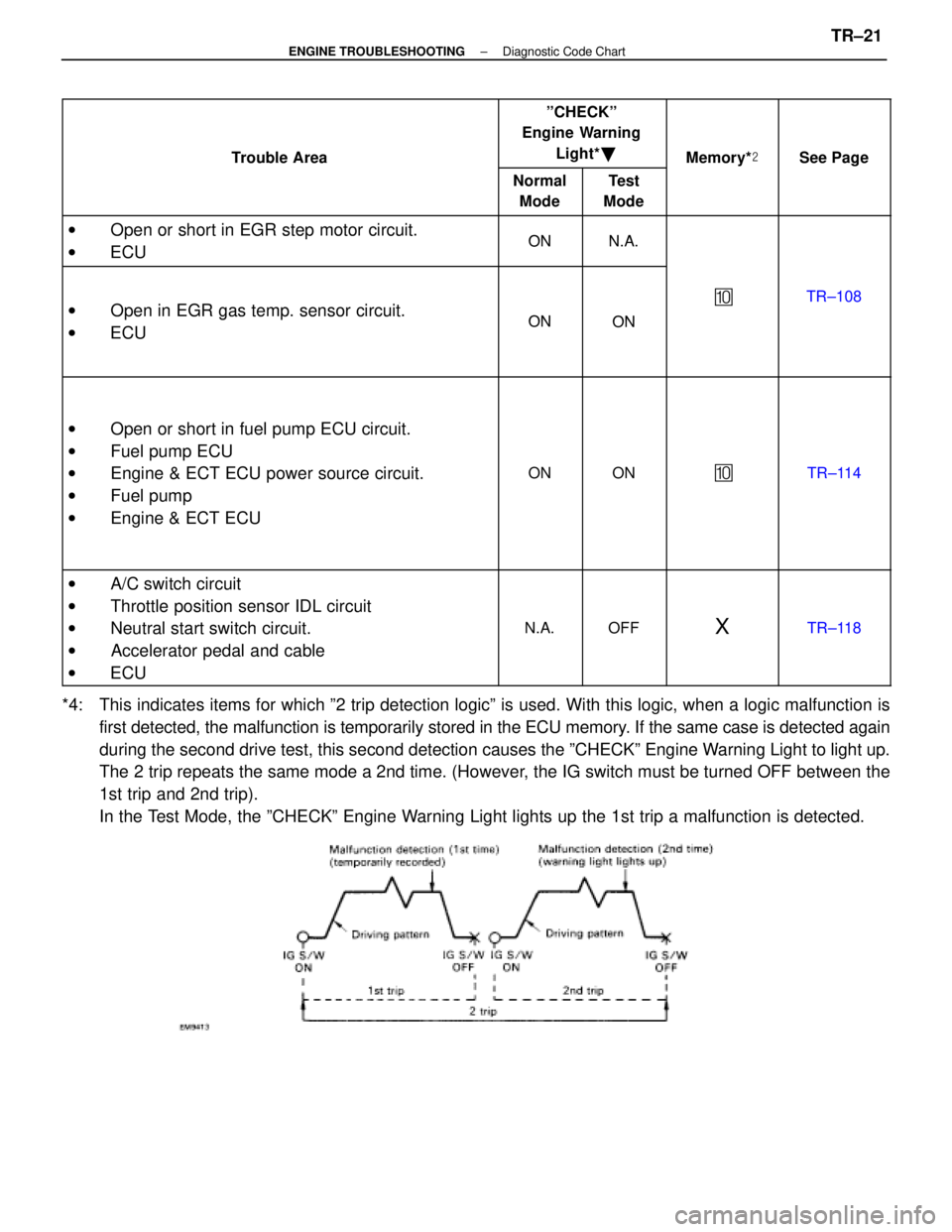
Trouble Area
ºCHECKº
Engine Warning
Light* �
Memory* �See PageTrouble Area
Normal
ModeTest
Mode
MemorySee Page
w Open or short in EGR step motor circuit.ONNA Oen or short in EGR ste motor circuit.
w ECUONN.A.
w Open in EGR gas temp. sensor circuit.ONON
�TR±108 Oen in EGR gas tem . sensor circuit.
w ECUONON
w Open or short in fuel pump ECU circuit.
w Fuel pump ECU
w Engine & ECT ECU power source circuit.
w Fuel pump
w Engine & ECT ECU
ONON�TR±114
w A/C switch circuit
w Throttle position sensor IDL circuit
w Neutral start switch circuit.
w Accelerator pedal and cable
w ECU
N.A.OFFXTR±118
*4: This indicates items for which º2 trip detection logicº is used. With this logic, when a lo\
gic malfunction is
first detected, the malfunction is temporarily stored in the ECU memory. If the same case is detected again
during the second drive test, this second detection causes the ºCHECK\
º Engine Warning Light to light up.
The 2 trip repeats the same mode a 2nd time. (However, the IG switch must be turned OFF between the
1st trip and 2nd trip).
In the Test Mode, the ºCHECKº Engine Warning Light lights up the 1st trip a malfunction is detected.
±
ENGINE TROUBLESHOOTING Diagnostic Code ChartTR±21
WhereEverybodyKnowsYourName
Page 3607 of 4087

FAIL±SAFE CHART
If any of the following codes is recorded, the ECU enters fail±
safe mode.
Code No.Fail±Safe OperationFail±Safe Deactivation Conditions
14Fuel cut1 IGF1 detected in consecutive 8 ignitions.
15Fuel cut1 IGF2 detected in consecutive 8 ignitions.
16Torque control prohibited.Returned to normal condition.
22THW is fixed at 805C (176 5F).Returned to normal condition.
24THA is fixed at 20 5C (68 5F).Returned to normal condition.
31
Ignition timing controlled between 10 5 ~ 30 5
BTDC,
Injection time controlled between 3 msec. ~ 30 m
sec., in relation to:
w Engine rpm
w Throttle angle
w ISC step value
KS input 15 times/sec. or more.
35Atmospheric pressure is fixed at 760 mmHg.Returned to normal condition.
The following 1 or 2 must be repeated at least 2
times consecutively.
41VTA1 is fixed at 051 When IDL is ON41VTA1 is fixed at 051 When IDL is ON
0.25 V � VTA1 � 0.95 V
2 When IDL is OFF2 When IDL is OFF
0.25 V � VTA1 � 4.9 V
The following 1 or 2 must be repeated at least 2
times consecutively.
47Value of VTA1 is used1 When IDL2 is ON47Value of VTA1 is used.1 When IDL2 is ON
0.25 V � VTA2 � 0.95 V
2 When IDL2 is OFF2 When IDL2 is OFF
0.25 V � VTA2 � 4.9 V
52Max. timeing retardation.IG switch OFF.
53Max. timeing retardation.Returned to normal condition.
55Max. timeing retardation.IG switch OFF.
Back±Up Function
If there is trouble with the program in the ECU and the ignition signals\
(IGT) are not output, the ECU controls
fuel injection and ignition timing at predetermined levels as a back±up f\
unction to make it possible to continue
to operate the vehicle.
Furthermore, the injection duration is calculated from the satrting sign\
al (STA) and the throttle position signal
(IDL). Also, the ignition timing is fixed at the initial ignition timing, 5 5 BTDC, without relation to the engine speed.
HINT: If the engine is controlled by the back±up function, the CHECK ENGIN\
E light lights up to warn the driver
of the malfunction but the diagnostic code is not output. TR±22
±
ENGINE TROUBLESHOOTING Fail±Safe Chart
WhereEverybodyKnowsYourName