Page 3669 of 4087
CIRCUIT DESCRIPTION (Cont'd)
DIAGNOSIS CODE DETECTION DRIVING PATTERN
Purpose of the driving pattern.
(a) To simulate diag. code detecting condition after diag. code is recorded.
(b) To check that the malfunction is corrected when the repair is completed co\
nfirming that diag. code isno longer detected.
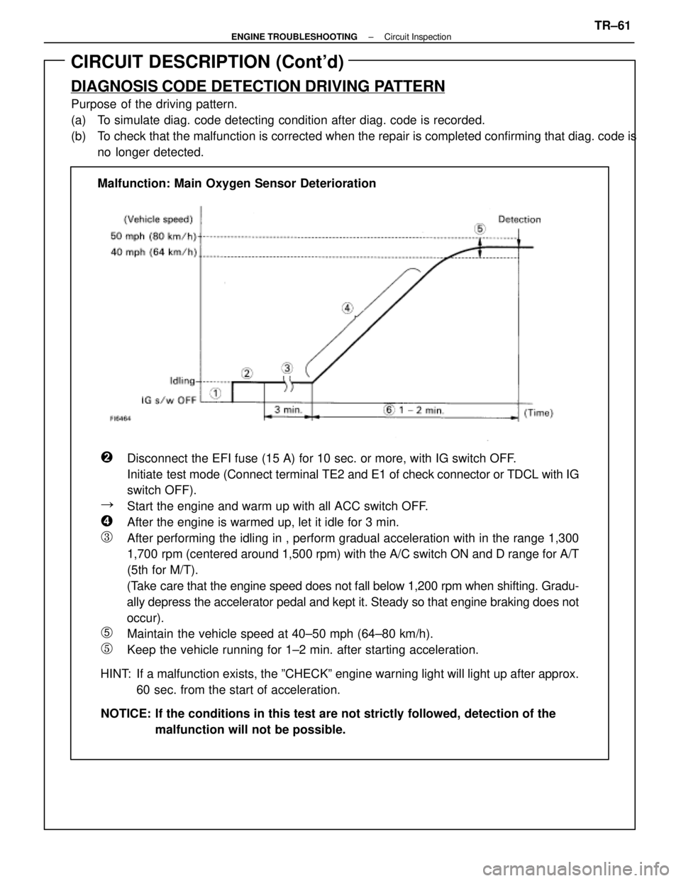
�Disconnect the EFI fuse (15 A) for 10 sec. or more, with IG switch OFF\
.
Initiate test mode (Connect terminal TE2 and E1 of check connector or TDCL with IG
switch OFF).
�Start the engine and warm up with all ACC switch OFF.
�After the engine is warmed up, let it idle for 3 min.
�After performing the idling in , perform gradual acceleration with in th\
e range 1,300
1,700 rpm (centered around 1,500 rpm) with the A/C switch ON and D range fo\
r A/T
(5th for M/T).
(Take care that the engine speed does not fall below 1,200 rpm when shifting.\
Gradu-
ally depress the accelerator pedal and kept it. Steady so that engine br\
aking does not
occur).
�Maintain the vehicle speed at 40±50 mph (64±80 km/h).
�Keep the vehicle running for 1±2 min. after starting acceleration.
HINT: If a malfunction exists, the ºCHECKº engine warning light will light\
up after approx. 60 sec. from the start of acceleration.
NOTICE: If the conditions in this test are not strictly followed, detection of t\
he malfunction will not be possible.
Malfunction: Main Oxygen Sensor Deterioration
±
ENGINE TROUBLESHOOTING Circuit InspectionTR±61
WhereEverybodyKnowsYourName
Page 3674 of 4087
CIRCUIT DESCRIPTION (Cont'd)
Purpose of the driving pattern.
(a) To simulate diag. code detecting condition after diag. code is recorded.
(b) To check that the malfunction is corrected when the repair is completed confirming that diag.code is no longer detected.
DIAGNOSIS CODE DETECTION DRIVING PATTERN
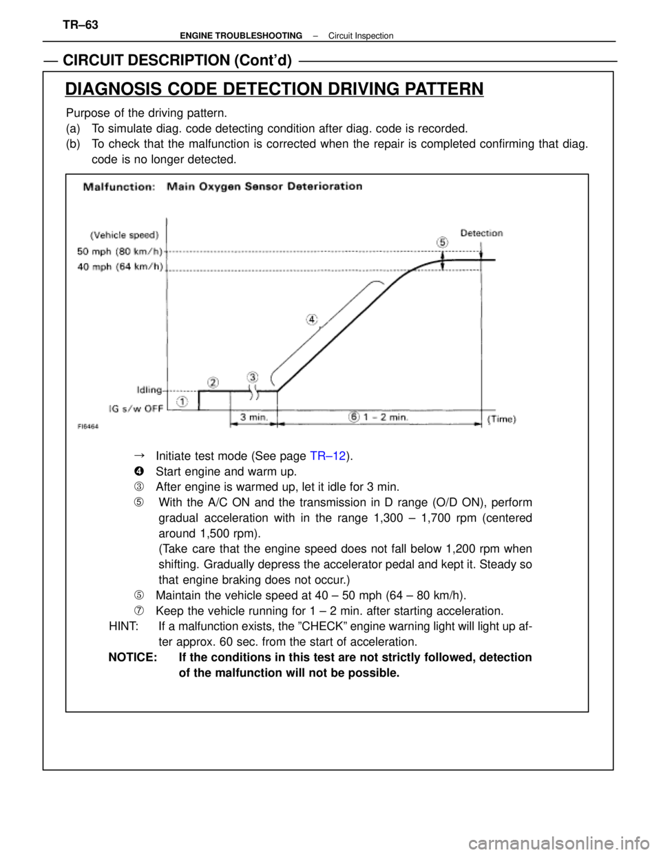
��Initiate test mode (See page TR±12).
��Start engine and warm up.
��After engine is warmed up, let it idle for 3 min.
�With the A/C ON and the transmission in D range (O/D ON), perform
gradual acceleration with in the range 1,300 ± 1,700 rpm (centered
around 1,500 rpm).
(Take care that the engine speed does not fall below 1,200 rpm when
shifting. Gradually depress the accelerator pedal and kept it. Steady so
that engine braking does not occur.)
��Maintain the vehicle speed at 40 ± 50 mph (64 ± 80 km/h).
��Keep the vehicle running for 1 ± 2 min. after starting acceleration.
HINT: If a malfunction exists, the ºCHECKº engine warning light will light\
up af-
ter approx. 60 sec. from the start of acceleration.
NOTICE: If the conditions in this test are not strictly followed, detection of the malfunction will not be possible.
TR±63
±
ENGINE TROUBLESHOOTING Circuit Inspection
WhereEverybodyKnowsYourName
Page 3687 of 4087
CIRCUIT DESCRIPTION (Cont'd)
DIAGNOSIS CODE DETECTION DRIVING PATTERN
Purpose of the driving pattern.
(a) To simulate diag. code detecting condition after diag. code is recorded.
(b) To check that the malfunction is corrected when the repair is completed co\
nfirming that diag. code isno longer detected.
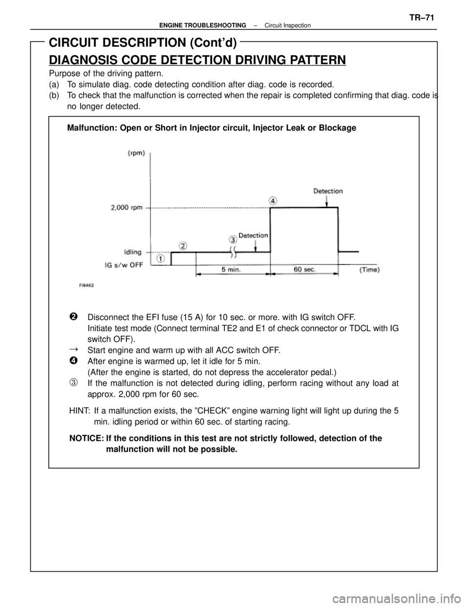
�Disconnect the EFI fuse (15 A) for 10 sec. or more. with IG switch OFF\
.
Initiate test mode (Connect terminal TE2 and E1 of check connector or TDCL with IG
switch OFF).
�Start engine and warm up with all ACC switch OFF.
�After engine is warmed up, let it idle for 5 min.
(After the engine is started, do not depress the accelerator pedal.)
�If the malfunction is not detected during idling, perform racing without any load at
approx. 2,000 rpm for 60 sec.
HINT: If a malfunction exists, the ºCHECKº engine warning light will light\
up during the 5 min. idling period or within 60 sec. of starting racing.
NOTICE: If the conditions in this test are not strictly followed, detection of t\
he malfunction will not be possible.
Malfunction: Open or Short in Injector circuit, Injector Leak or Blockag\
e
±
ENGINE TROUBLESHOOTING Circuit InspectionTR±71
WhereEverybodyKnowsYourName
Page 3695 of 4087
CIRCUIT DESCRIPTION (Cont'd)
DIAGNOSIS CODE DETECTION DRIVING PATTERN
Purpose of the driving pattern.
(a) To simulate diag. code detecting condition after diag. code is recorded.
(b) To check that the malfunction is corrected when the repair is completed c\
onfirming that diag. code is no longer detected.
Malfunction: Open or Short in Main Oxygen Sensor
�Initiate test mode (See page TR±12).
�Start engine and warm up.
�After engine is warmed up, let it idle for 3 min.
�Perform quick racing to 4,000 rpm three times by accelerator pedal.
�After performing the racing in (4), perform racing at 2,000 rpm for 90\
sec.
HINT: If a malfunction exists, the ºCHECKº engine warning light will light up after 90 sec. from the start of racing.
NOTICE: If the conditions in this test are not strictly followed, detection of t\
he malfunction will not be possible.
TR±75±
ENGINE TROUBLESHOOTING Circuit Inspection
WhereEverybodyKnowsYourName
Page 3696 of 4087
CIRCUIT DESCRIPTION (Cont'd)
DIAGNOSIS CODE DETECTION DRIVING PATTERN
Purpose of the driving pattern.
(a) To simulate diag. code detecting condition after diag. code is recorded.
(b) To check that the malfunction is corrected when the repair is completed co\
nfirming that diag. codeis no longer detected.
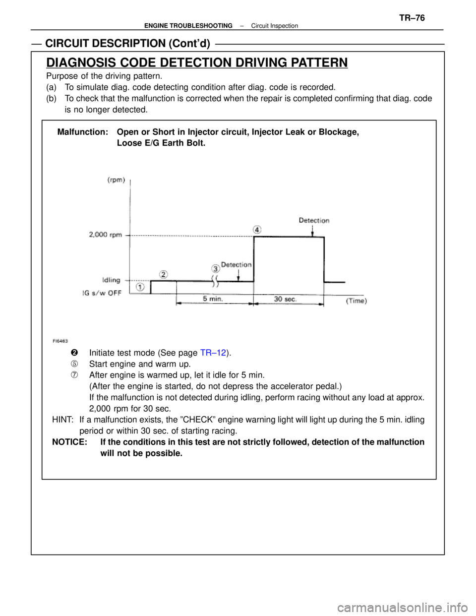
Malfunction: Open or Short in Injector circuit, Injector Leak or Blockage, Loose E/G Earth Bolt.
�Initiate test mode (See page TR±12).
�Start engine and warm up.
�After engine is warmed up, let it idle for 5 min.
(After the engine is started, do not depress the accelerator pedal.)
\bIf the malfunction is not detected during idling, perform racing without a\
ny load at approx.
2,000 rpm for 30 sec.
HINT: If a malfunction exists, the ºCHECKº engine warning light will light up during the 5 min. idling
period or within 30 sec. of starting racing.
NOTICE: If the conditions in this test are not strictly followed, detection of the\
malfunction will not be possible.
±
ENGINE TROUBLESHOOTING Circuit InspectionTR±76
WhereEverybodyKnowsYourName
Page 3703 of 4087
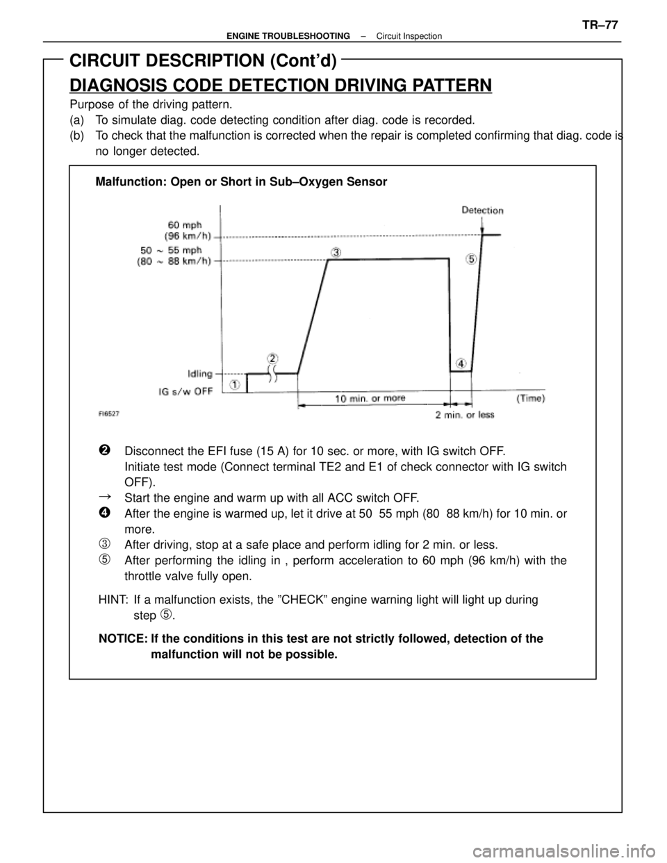
CIRCUIT DESCRIPTION (Cont'd)
DIAGNOSIS CODE DETECTION DRIVING PATTERN
Purpose of the driving pattern.
(a) To simulate diag. code detecting condition after diag. code is recorded.
(b) To check that the malfunction is corrected when the repair is completed co\
nfirming that diag. code isno longer detected.
�Disconnect the EFI fuse (15 A) for 10 sec. or more, with IG switch OFF\
.
Initiate test mode (Connect terminal TE2 and E1 of check connector with\
IG switch
OFF).
�Start the engine and warm up with all ACC switch OFF.
�After the engine is warmed up, let it drive at 50 55 mph (80 88 km/h) for\
10 min. or
more.
�After driving, stop at a safe place and perform idling for 2 min. or les\
s.
�After performing the idling in , perform acceleration to 60 mph (96 km/h) with the
throttle valve fully open.
HINT: If a malfunction exists, the ºCHECKº engine warning light will lig\
ht up during step
�.
NOTICE: If the conditions in this test are not strictly followed, detection of t\
he malfunction will not be possible.
Malfunction: Open or Short in Sub±Oxygen Sensor
±
ENGINE TROUBLESHOOTING Circuit InspectionTR±77
WhereEverybodyKnowsYourName
Page 3708 of 4087
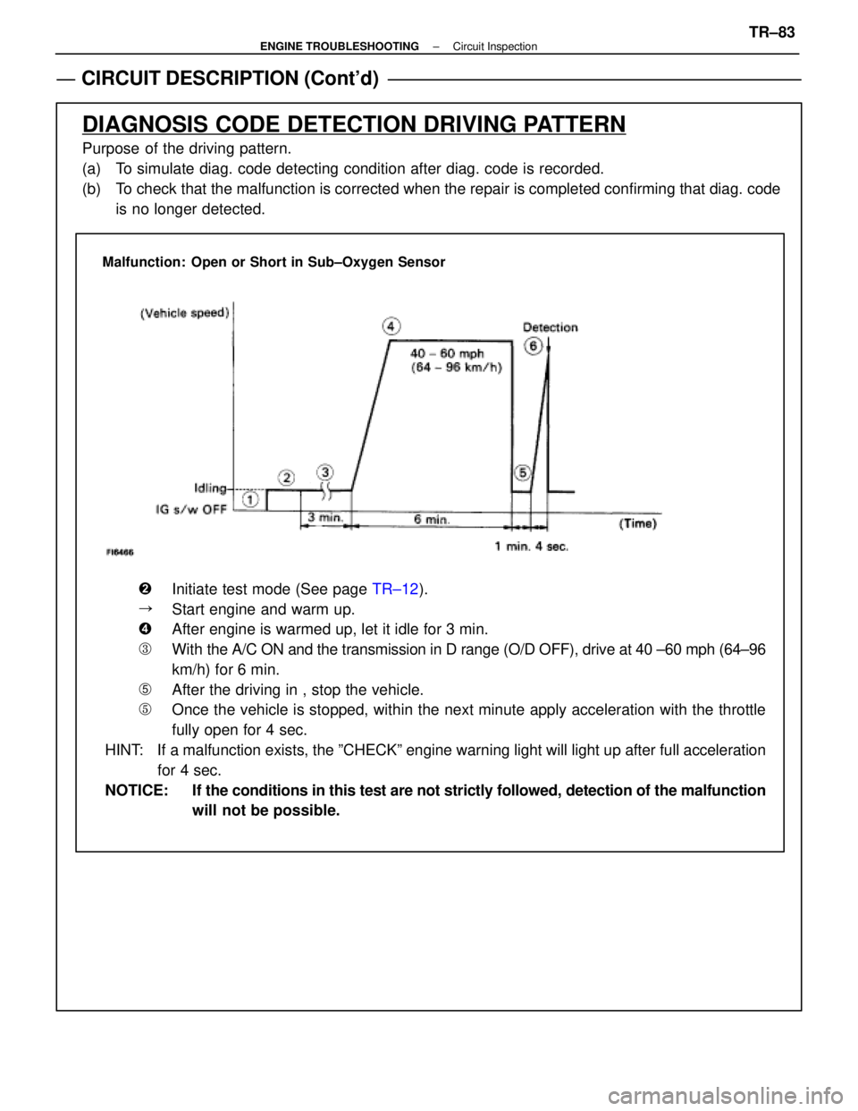
CIRCUIT DESCRIPTION (Cont'd)
DIAGNOSIS CODE DETECTION DRIVING PATTERN
Purpose of the driving pattern.
(a) To simulate diag. code detecting condition after diag. code is recorded.
(b) To check that the malfunction is corrected when the repair is completed co\
nfirming that diag. codeis no longer detected.
Malfunction: Open or Short in Sub±Oxygen Sensor
�Initiate test mode (See page TR±12).
�Start engine and warm up.
�After engine is warmed up, let it idle for 3 min.
�With the A/C ON and the transmission in D range (O/D OFF), drive at 40 ±\
60 mph (64±96
km/h) for 6 min.
�After the driving in , stop the vehicle.
�Once the vehicle is stopped, within the next minute apply acceleration w\
ith the throttle
fully open for 4 sec.
HINT: If a malfunction exists, the ºCHECKº engine warning light will light\
up after full acceleration for 4 sec.
NOTICE: If the conditions in this test are not strictly followed, detection of the\
malfunction will not be possible.
±
ENGINE TROUBLESHOOTING Circuit InspectionTR±83
WhereEverybodyKnowsYourName
Page 3714 of 4087
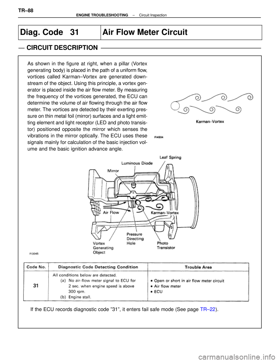
Diag. Code 31Air Flow Meter Circuit
CIRCUIT DESCRIPTION
As shown in the figure at right, when a pillar (Vortex
generating body) is placed in the path of a uniform flow,
vortices called Karman±Vortex are generated down-
stream of the object. Using this principle, a vortex gen-
erator is placed inside the air flow meter. By measuring
the frequency of the vortices generated, the ECU can
determine the volume of air flowing through the air flow
meter. The vortices are detected by their exerting pres-
sure on thin metal foil (mirror) surfaces and a light emit-
ting element and light receptor (LED and photo transis-
tor) positioned opposite the mirror which senses the
vibrations in the mirror optically. The ECU uses these
signals mainly for calculation of the basic injection vol-
ume and the basic ignition advance angle.
If the ECU records diagnostic code º31º, it enters fail safe mode \
(See page TR±22).
TR±88
±
ENGINE TROUBLESHOOTING Circuit Inspection
WhereEverybodyKnowsYourName