Page 1528 of 4087
COMPONENTS FOR CYLINDER BLOCK
DISASSEMBLY AND ASSEMBLY
EG0BS±0E
EG±152±
1UZ±FE ENGINE ENGINE MECHANICAL
WhereEverybodyKnowsYourName
Page 1529 of 4087
PREPARATION FOR DISASSEMBLY
EG34Y±01
(See Components for Cylinder Block Disassembly and As-sembly)
1. REMOVE DRIVE PLATE Remove the 8 bolts, front spacer drive plate and rear spacer.
2. INSTALL ENGINE TO ENGINE STAND FOR DISASSEMBLY
3. REMOVE TIMING BELT AND PULLEYS (See pages EG±49 to 57)
4. REMOVE CYLINDER HEAD (See pages EG±75 to 93)
5. REMOVE RH ENGINE MOUNTING BRACKET Remove the 4 bolts and mounting bracket.
6. REMOVE LH ENGINE MOUNTING BRACKET
(a) Remove the 4 bolts and mounting bracket.
(b) Remove the bolt, and disconnect the engine wire from the mounting bracket.
7. REMOVE STARTER
(a) Remove the 2 bolts, and disconnect the starter from the cylinder block.
±
1UZ±FE ENGINE ENGINE MECHANICALEG±153
WhereEverybodyKnowsYourName
Page 1530 of 4087
(b) Disconnect the engine wire clamp from the bracket on thestarter.
(c) Remove the nut, and disconnect the starter wire.
(d) Disconnect the starter connector, and remove the starter.
8. REMOVE KNOCK SENSORS
(a) Disconnect the 2 knock sensor connectors.
(b) Using SST, remove the 2 knock sensors.
SST 09816±30010
9. REMOVE WATER BYPASS PIPE
(a) Remove the 2 bolts.
(b) Pull out the water bypass pipe from the water pump.
(c) Remove the O±ring from the water bypass pipe.
10. REMOVE ENGINE WIRE
(a) Disconnect the following connector: wCrankshaft position sensor connector
w Oil pressure switch connector
w Oil level sensor connector
(b) Remove the 3 bolts and engine wire cover from the LH side of the cylinder block.
(c) Remove the 2 bolts and engine wire.
EG±154
±
1UZ±FE ENGINE ENGINE MECHANICAL
WhereEverybodyKnowsYourName
Page 1531 of 4087
11. REMOVE WATER PUMP
(a) Remove the 5 bolts, 2 stud bolts and nut.
(b) Using a screwdriver remove the water pump by prying theportions between the water pump and cylinder block.
12. REMOVE NO.2 AND NO.1 OIL PANS
(See steps 9 to 14 on pages EG±501 and 502)
13. REMOVE OIL PUMP
(a) Remove the 8 bolts.
(b) Using a screwdriver, remove the oil pump by prying the portions between the oil pump and cylinder block.
(c) Remove the O±ring from the cylinder block.
14. REMOVE GENERATOR BRACKET
Remove the bolt and generator bracket.
15. REMOVE WATER SEAL PLATE
Remove the 2 bolts and seal plate.
±
1UZ±FE ENGINE ENGINE MECHANICALEG±155
WhereEverybodyKnowsYourName
Page 1532 of 4087

CYLINDER BLOCK DISASSEMBLY
EG1KT±04
(See Components for Cylinder Block Disassembly and As-sembly)
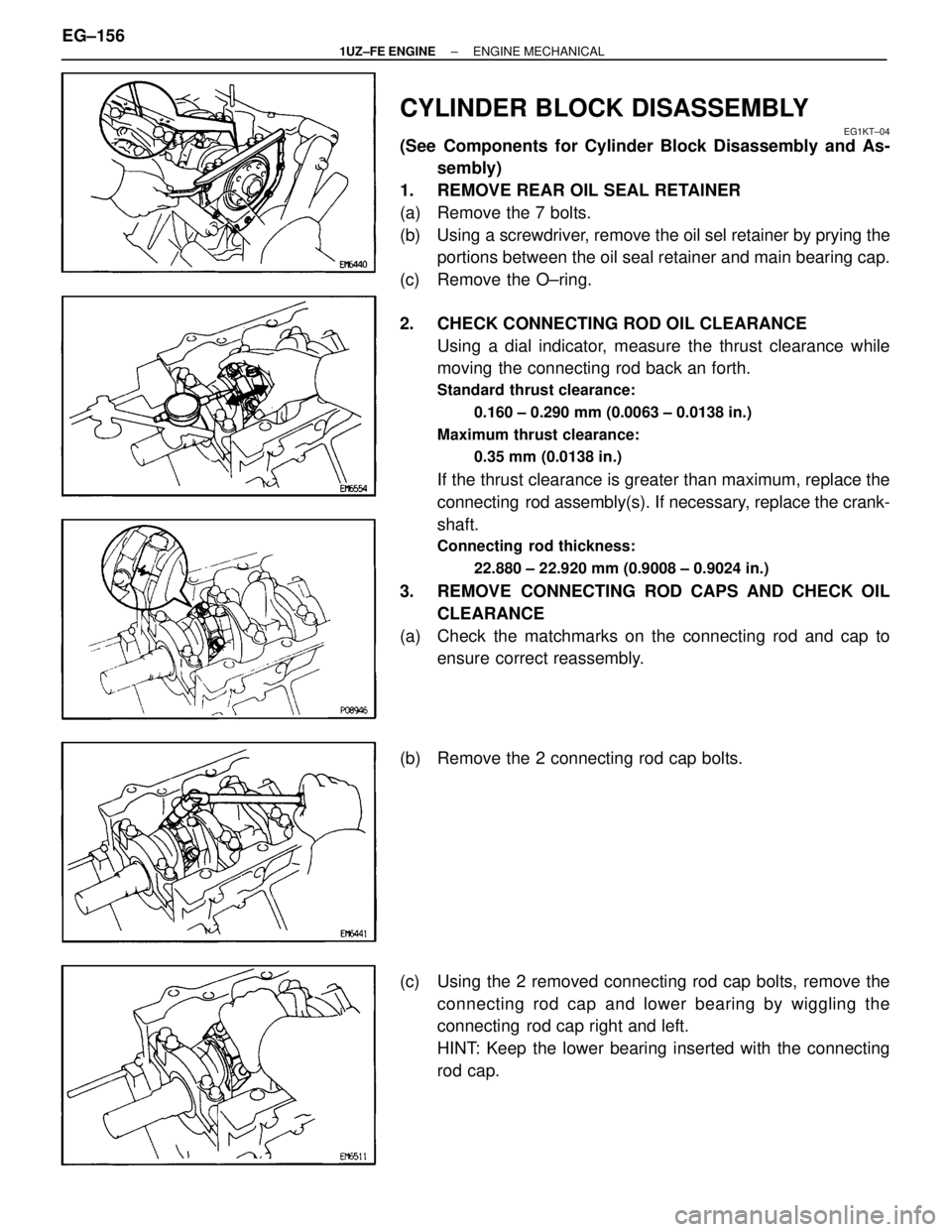
1. REMOVE REAR OIL SEAL RETAINER
(a) Remove the 7 bolts.
(b) Using a screwdriver, remove the oil sel retainer by prying the portions between the oil seal retainer and main bearing cap.
(c) Remove the O±ring.
2. CHECK CONNECTING ROD OIL CLEARANCE Using a dial indicator, measure the thrust clearance while
moving the connecting rod back an forth.
Standard thrust clearance:
0.160 ± 0.290 mm (0.0063 ± 0.0138 in.)
Maximum thrust clearance: 0.35 mm (0.0138 in.)
If the thrust clearance is greater than maximum, replace the
connecting rod assembly(s). If necessary, replace the crank-
shaft.
Connecting rod thickness:
22.880 ± 22.920 mm (0.9008 ± 0.9024 in.)
3. REMOVE CONNECTING ROD CAPS AND CHECK OILCLEARANCE
(a) Check the matchmarks on the connecting rod and cap to ensure correct reassembly.
(b) Remove the 2 connecting rod cap bolts.
(c) Using the 2 removed connecting rod cap bolts, remove the connecting rod cap and lower bearing by wiggling the
connecting rod cap right and left.
HINT: Keep the lower bearing inserted with the connecting
rod cap.
EG±156
±
1UZ±FE ENGINE ENGINE MECHANICAL
WhereEverybodyKnowsYourName
Page 1533 of 4087
(d) Clean the crank pin and bearing.
(e) Check the crank pin and bearing for pitting and scratches.If the crank pin or bearing is damaged, replace the bearings.
If necessary, replace the crankshaft.
(f) Lay a strip of Plastigage across the crank pin.
(g) Install the connecting rod cap with the 2 bolts. (See step 7 on page EG±183)
Torque:
1st 25 N Vm (250 kgf Vcm, 18 ft Vlbf)
2nd Turn 90 5
NOTICE: Do not turn the crankshaft.
(h) Remove the 2 bolts, connecting rod cap and lower bearing. (See procedure (b) and (c) above)
(i) Measure the Plastigage at its widest point.
Standard oil clearance: 0.027 ± 0.053 mm (0.0011 ± 0.0021 in.)
Maximum oil clearance: 0.065 mm (0.0026 in.)
If the oil clearance is greater than maximum, replace the
bearings. If necessary, replace the crankshaft.
±
1UZ±FE ENGINE ENGINE MECHANICALEG±157
WhereEverybodyKnowsYourName
Page 1534 of 4087

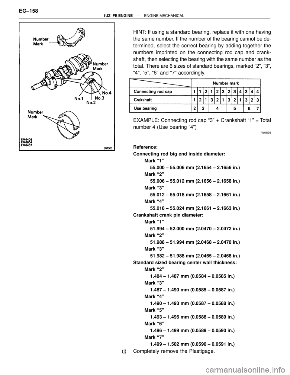
HINT: If using a standard bearing, replace it with one having
the same number. If the number of the bearing cannot be de-
termined, select the correct bearing by adding together the
numbers imprinted on the connecting rod cap and crank-
shaft, then selecting the bearing with the same number as the
total. There are 6 sizes of standard bearings, marked ª2º, ª3º,
ª4º, ª5º, ª6º and ª7º accordingly.
EXAMPLE: Connecting rod cap ª3º + Crankshaft ª1º = Total
number 4 (Use bearing ª4º)
V01595
Reference:
Connecting rod big end inside diameter:
Mark ª1º55.000 ± 55.006 mm (2.1654 ± 2.1656 in.)
Mark ª2º
55.006 ± 55.012 mm (2.1656 ± 2.1658 in.)
Mark ª3º 55.012 ± 55.018 mm (2.1658 ± 2.1661 in.)
Mark ª4º
55.018 ± 55.024 mm (2.1661 ± 2.1663 in.)
Crankshaft crank pin diameter: Mark ª1º51.994 ± 52.000 mm (2.0470 ± 2.0472 in.)
Mark ª2º
51.988 ± 51.994 mm (2.0468 ± 2.0470 in.)
Mark ª3º 51.982 ± 51.988 mm (2.0465 ± 2.0468 in.)
Standard sized bearing center wall thickness:
Mark ª2º1.484 ± 1.487 mm (0.0584 ± 0.0585 in.)
Mark ª3º 1.487 ± 1.490 mm (0.0585 ± 0.0587 in.)
Mark ª4º
1.490 ± 1.493 mm (0.0587 ± 0.0588 in.)
Mark ª5º 1.493 ± 1.496 mm (0.0588 ± 0.0589 in.)
Mark ª6º
1.496 ± 1.499 mm (0.0589 ± 0.0590 in.)
Mark ª7º 1.499 ± 1.502 mm (0.0590 ± 0.0591 in.)
(j) Completely remove the Plastigage.
EG±158
±
1UZ±FE ENGINE ENGINE MECHANICAL
WhereEverybodyKnowsYourName
Page 1535 of 4087
4. REMOVE PISTON AND CONNECTING RODASSEMBLIES
(a) Using a ridge reamer, remove all the carbon from the top of
the cylinder.
(b) Push the piston, connecting rod assembly and upper bearing through the top of the cylinder block.
HINT:
wKeep the bearings, connecting rod and cap together.
w Arrange the piston and connecting rod assemblies in
correct order.
5. CHECK CRANKSHAFT THRUST CLEARANCE Using a dial indi cator, measure the thrust clearance while pry-
ing the crankshaft back and forth with a screwdriver.
Standard thrust clearance:
0.020 ± 0.220 mm (0.0008 ± 0.0087 in.)
Maximum thrust clearance: 0.30 mm (0.0118 in.)
If the thrust clearance is greater than maximum, replace the
thrust washers as a set.
Thrust washer thickness:2.440 ± 2.490 mm (0.0961 ± 0.0980 in.)
±
1UZ±FE ENGINE ENGINE MECHANICALEG±159
WhereEverybodyKnowsYourName