Page 1536 of 4087

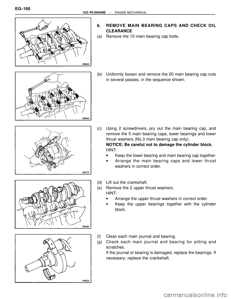
6. REMOVE MAIN BEARING CAPS AND CHECK OILCLEARANCE
(a) Remove the 10 main bearing cap bolts.
(b) Uniformly loosen and remove the 20 main bearing cap nuts
in several passes, in the sequence shown.
(c) Using 2 screwdrivers, pry out the main bearing cap, and remove the 5 main bearing caps, lower bearings and lower
thrust washers (No.3 main bearing cap only).
NOTICE: Be careful not to damage the cylinder block.
HINT:
wKeep the lower bearing and main bearing cap together.
w Arrange the main bearing caps and lower thrust
washers in correct order.
(d) Lift out the crankshaft.
(e) Remove the 2 upper thrust washers. HINT:
wArrange the upper thrust washers in correct order.
w Keep the upper bearings together with the cylinder
block.
(f) Clean each main journal and bearing.
(g) Ch e ck ea ch ma in jo u rn a l an d be a rin g fo r pittin g an d scratches.
If the journal or bearing is damaged, replace the bearings. If
necessary, replace the crankshaft.
EG±160
±
1UZ±FE ENGINE ENGINE MECHANICAL
WhereEverybodyKnowsYourName
Page 1537 of 4087
(h) Install the 5 main bearing caps with the 20 nuts and ten bolts.
Do not install the crankshaft.
(See step 4 on page EG±180)
Torque:
Nut1st 27 N Vm (275 kgf Vcm, 20 ft Vlbf)
2nd Turn 90 5
Bolt 49 N Vm (500 kgf Vcm, 36 ft Vlbf)
(i) Using a cylinder gauge, measure the inside diameter of the
the main bearing.
Bearing inside diameter:
67.026 ± 67.033 mm (2.6388 ± 2.6391 in.)
(j) Using a, micrometer measure the diameter of the mainjournal
Main journal diameter:
66.988 ± 67.000 mm (2.6373 ± 2.6378 in.)
(k) Subtract the main journal diameter measurement from themain bearing inside diameter measurement.
Standard clearance:
0.026 ± 0.045 mm (0.0010 ± 0.0018 in.)
Maximum clearance: 0.055 mm (0.0022 in.)
If the oil clearance is greater than maximum, replace the
bearings. If necessary, replace the crankshaft.
±
1UZ±FE ENGINE ENGINE MECHANICALEG±161
WhereEverybodyKnowsYourName
Page 1538 of 4087

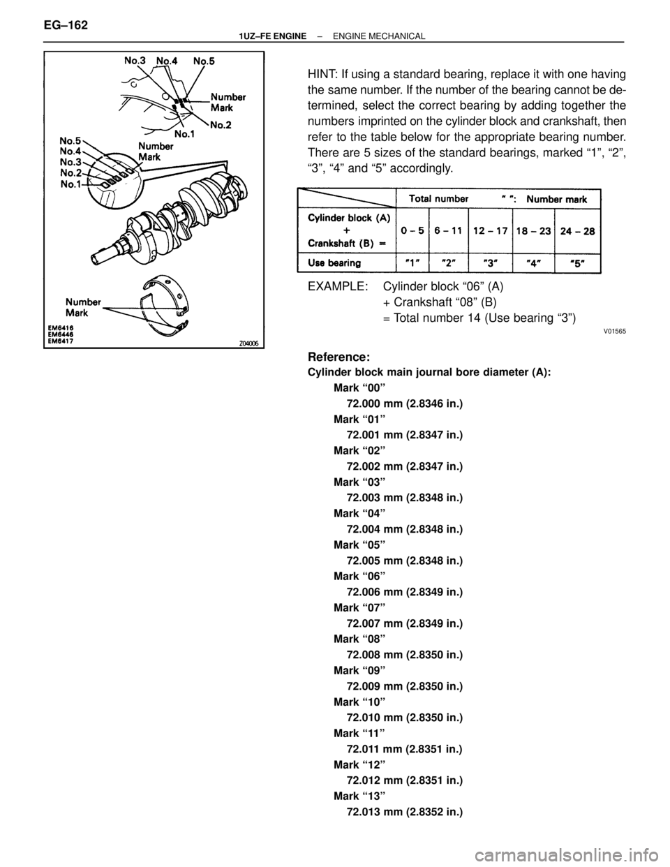
HINT: If using a standard bearing, replace it with one having
the same number. If the number of the bearing cannot be de-
termined, select the correct bearing by adding together the
numbers imprinted on the cylinder block and crankshaft, then
refer to the table below for the appropriate bearing number.
There are 5 sizes of the standard bearings, marked ª1º, ª2º,\
ª3º, ª4º and ª5º accordingly.
EXAMPLE: Cylinder block ª06º (A) + Crankshaft ª08º (B)
= Total number 14 (Use bearing ª3º)
V01565
Reference:
Cylinder block main journal bore diameter (A):
Mark ª00º72.000 mm (2.8346 in.)
Mark ª01º 72.001 mm (2.8347 in.)
Mark ª02º 72.002 mm (2.8347 in.)
Mark ª03º 72.003 mm (2.8348 in.)
Mark ª04º 72.004 mm (2.8348 in.)
Mark ª05º 72.005 mm (2.8348 in.)
Mark ª06º
72.006 mm (2.8349 in.)
Mark ª07º 72.007 mm (2.8349 in.)
Mark ª08º
72.008 mm (2.8350 in.)
Mark ª09º 72.009 mm (2.8350 in.)
Mark ª10º 72.010 mm (2.8350 in.)
Mark ª11º 72.011 mm (2.8351 in.)
Mark ª12º 72.012 mm (2.8351 in.)
Mark ª13º 72.013 mm (2.8352 in.)
EG±162±
1UZ±FE ENGINE ENGINE MECHANICAL
WhereEverybodyKnowsYourName
Page 1539 of 4087
Mark ª14º72.014 mm (2.8352 in.)
Mark ª15º
72.015 mm (2.8352 in.)
Mark ª16º 72.016 mm (2.8353 in.)
Crankshaft main journal diameter (B): Mark ª00º
67.000 mm (2.8378 in.)
Mark ª01º 66.999 mm (2.6378 in.)
Mark ª02º
66.998 mm (2.6377 in.)
Mark ª03º 66.997 mm (2.5377 in.)
Mark ª04º 66.996 mm (2.6376 in.)
Mark ª05º 66.995 mm (2.6376 in.)
Mark ª06º 66.994 mm (2.6376 in.)
Mark ª07º 66.993 mm (2.6375 in.)
Mark ª08º 66.992 mm (2.6375 in.)
Mark ª09º
66.991 mm (2.6374 in.)
Mark ª10º 66.990 mm (2.6374 in.)
Mark ª11º
66.989 mm (2.6374 in.)
Mark ª12º 66.988 mm (2.6373 in.)
Standard sized bearing center wall thickness: Mark ª1º
2.486 ± 2.489 mm (0.0979 ± 0.0980 in.)
Mark ª2º 2.489 ± 2.492 mm (0.0980 ± 0.0981 in.)
Mark ª3º
2.492 ± 2.495 mm (0.0981 ± 0.0982 in.)
Mark ª4º 2.495 ± 2.498 mm (0.0982 ± 0.0983 in.)
Mark ª5º 2.498 ± 2.501 mm (0.0983 ± 0.0985 in.)
±
1UZ±FE ENGINE ENGINE MECHANICALEG±163
WhereEverybodyKnowsYourName
Page 1540 of 4087

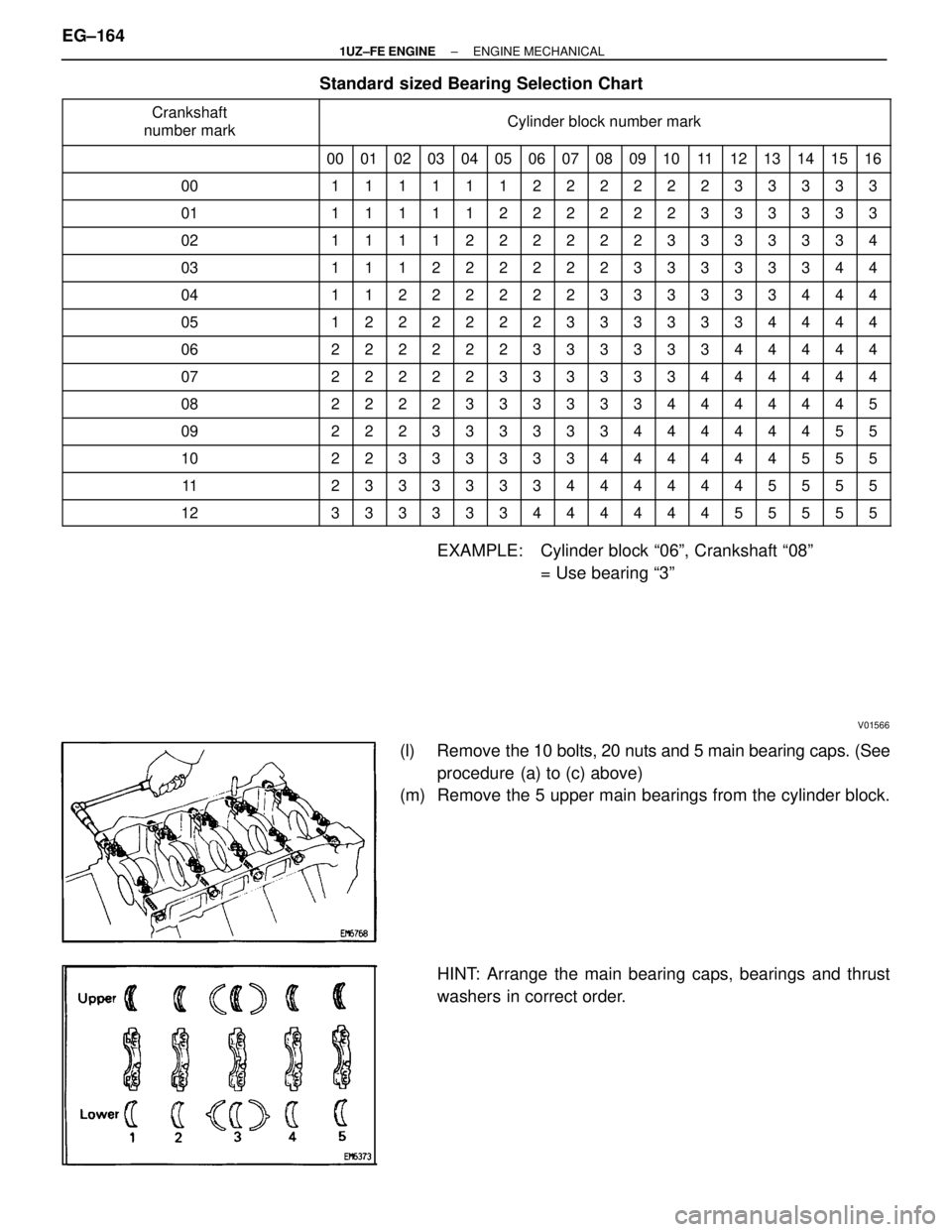
Standard sized Bearing Selection Chart
������������ �
�����������
������������
Crankshaft
number mark������������������\
������� �
������������������\
������
������������������\
�������
Cylinder block number mark
������������ �������������� ��00��� ���01�� ��02�� ��03��� ���04�� ��05��� ���06�� ��07�� ��08�� ��09�� ��10��� ���11�� ��12��� ���13�� ��14�� ��15��� ���16
������������ ������������00�� ��1��� ���1�� ��1�� ��1��� ���1�� ��1��� ���2�� ��2�� ��2�� ��2�� ��2��� ���2�� ��3��� ���3�� ��3�� ��3��� ���3
������������ ������������01�� ��1��� ���1�� ��1�� ��1��� ���1�� ��2��� ���2�� ��2�� ��2�� ��2�� ��2��� ���3�� ��3��� ���3�� ��3�� ��3��� ���3
������������ ������������02�� ��1��� ���1�� ��1�� ��1��� ���2�� ��2��� ���2�� ��2�� ��2�� ��2�� ��3��� ���3�� ��3��� ���3�� ��3�� ��3��� ���4
������������ ������������03�� ��1��� ���1�� ��1�� ��2��� ���2�� ��2��� ���2�� ��2�� ��2�� ��3�� ��3��� ���3�� ��3��� ���3�� ��3�� ��4��� ���4������������ ������������04�� ��1��� ���1�� ��2�� ��2��� ���2�� ��2��� ���2�� ��2�� ��3�� ��3�� ��3��� ���3�� ��3��� ���3�� ��4�� ��4��� ���4������������ �
�����������
������������05
�� ��
��
1
��� �
��
���2
�� ��
��
2
�� ��
��
2
��� �
��
���2
�� ��
��
2
��� �
��
���2
�� ��
��
3
�� �
�
��
3
��
��
��3
�� ��
��
3
��� �
��
���3
�� ��
��
3
��� �
��
���4
�� ��
��
4
�� ��
��
4
��� �
��
���4
������������ ������������06�� ��2��� ���2�� ��2�� ��2��� ���2�� ��2��� ���3�� ��3�� ��3�� ��3�� ��3��� ���3�� ��4��� ���4�� ��4�� ��4��� ���4
������������ ������������07�� ��2��� ���2�� ��2�� ��2��� ���2�� ��3��� ���3�� ��3�� ��3�� ��3�� ��3��� ���4�� ��4��� ���4�� ��4�� ��4��� ���4
������������ ������������08�� ��2��� ���2�� ��2�� ��2��� ���3�� ��3��� ���3�� ��3�� ��3�� ��3�� ��4��� ���4�� ��4��� ���4�� ��4�� ��4��� ���5
������������ ������������09�� ��2��� ���2�� ��2�� ��3��� ���3�� ��3��� ���3�� ��3�� ��3�� ��4�� ��4��� ���4�� ��4��� ���4�� ��4�� ��5��� ���5
������������ ������������10�� ��2��� ���2�� ��3�� ��3��� ���3�� ��3��� ���3�� ��3�� ��4�� ��4�� ��4��� ���4�� ��4��� ���4�� ��5�� ��5��� ���5������������ ������������11�� ��2��� ���3�� ��3�� ��3��� ���3�� ��3��� ���3�� ��4�� ��4�� ��4�� ��4��� ���4�� ��4��� ���5�� ��5�� ��5��� ���5������������ �
�����������
������������12
�� ��
��
3
��� �
��
���3
�� ��
��
3
�� ��
��
3
��� �
��
���3
�� ��
��
3
��� �
��
���4
�� ��
��
4
�� �
�
��
4
��
��
��4
�� ��
��
4
��� �
��
���4
�� ��
��
5
��� �
��
���5
�� ��
��
5
�� ��
��
5
��� �
��
���5
EXAMPLE: Cylinder block ª06º, Crankshaft ª08º
= Use bearing ª3º
V01566
(l) Remove the 10 bolts, 20 nuts and 5 main bearing caps. (Seeprocedure (a) to (c) above)
(m) Remove the 5 upper main bearings from the cylinder block.
HINT: Arrange the main bearing caps, bearings and thrust
washers in correct order.
EG±164
±
1UZ±FE ENGINE ENGINE MECHANICAL
WhereEverybodyKnowsYourName
Page 1541 of 4087
CYLINDER BLOCK INSPECTION AND
REPAIR
EG1KU±01
1. CLEAN CYLINDER BLOCK
A. Remove gasket materialUsing a gasket scraper, remove all the gasket material from
the top surface of the cylinder block.
B. Clean cylinder block
Using a soft brush and solvent, thoroughly clean the cylinder
block.
NOTICE: If the cylinder is washed at high temperatures, the
cylinder liner sticks out beyond the cylinder block, so always
wash the cylinder block at temperature of 45 � or less.
2. INSPECT TOP SURFACE OF CYLINDER BLOCK FOR
FLATNESS
Using a precision straight edge and feeler gauge, measure
the surface contacting the cylinder head gasket for warpage.
Maximum warpage:
0.07 mm (0.0028 in.)
If warpage is greater than maximum, replace the cylinder
block.
3. INSPECT CYLINDER FOR VERTICAL SCRATCHES Visually check the cylinder for vertical scratches.
If deep scratches are present, replace the cylinder block.
±
1UZ±FE ENGINE ENGINE MECHANICALEG±165
WhereEverybodyKnowsYourName
Page 1542 of 4087

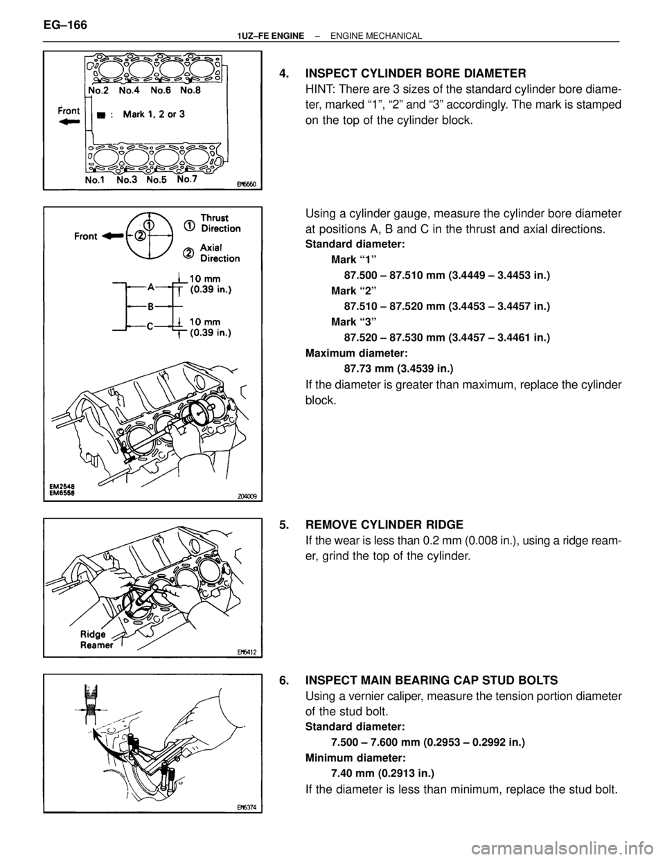
4. INSPECT CYLINDER BORE DIAMETERHINT: There are 3 sizes of the standard cylinder bore diame-
ter, marked ª1º, ª2º and ª3º accordingly. The mark is stamped
on the top of the cylinder block.
Using a cylinder gauge, measure the cylinder bore diameter
at positions A, B and C in the thrust and axial directions.
Standard diameter:
Mark ª1º87.500 ± 87.510 mm (3.4449 ± 3.4453 in.)
Mark ª2º 87.510 ± 87.520 mm (3.4453 ± 3.4457 in.)
Mark ª3º 87.520 ± 87.530 mm (3.4457 ± 3.4461 in.)
Maximum diameter: 87.73 mm (3.4539 in.)
If the diameter is greater than maximum, replace the cylinder
block.
5. REMOVE CYLINDER RIDGE If the wear is less than 0.2 mm (0.008 in.), using a ridge ream-
er, grind the top of the cylinder.
6. INSPECT MAIN BEARING CAP STUD BOLTS Using a vernier caliper, measure the tension portion diameter
of the stud bolt.
Standard diameter:
7.500 ± 7.600 mm (0.2953 ± 0.2992 in.)
Minimum diameter: 7.40 mm (0.2913 in.)
If the diameter is less than minimum, replace the stud bolt.
EG±166
±
1UZ±FE ENGINE ENGINE MECHANICAL
WhereEverybodyKnowsYourName
Page 1543 of 4087
7. IF NECESSARY, REPLACE MAIN BEARING CAP STUDBOLTS
(a) Using the 2 main bearing cap nuts, remove the stud bolt.
(b) Apply a light coat of engine oil on the threads and under
flange of new stud bolts.
(c) Using the 2 main bearing cap nuts, install the stud bolt.
Torque: 15 N Vm (150 kgf Vcm, 11 ft Vlbf)
HINT: Stud bolts come in lengths of 90.0 mm (3.543 in.) and
101.5 mm (3.996 in.). Install the 101.5 mm (3.996 in.) bolts
in inside positions. Install the 90.0 mm (3.543 in.) bolts in out-
side positions.
PISTON AND CONNECTING ROD
DISASSEMBLY
EG0BV±06
1. CHECK FIT BETWEEN PISTON AND PISTON PIN
Try to move the piston back and forth on the piston pin.
If any movement is felt, replace the piston and pin as a set.
2. REMOVE PISTON RINGS
(a) Using a piston ring expander, remove the 2 compression rings.
±
1UZ±FE ENGINE ENGINE MECHANICALEG±167
WhereEverybodyKnowsYourName