Page 745 of 4087

NGOK
NG
OK
1
2
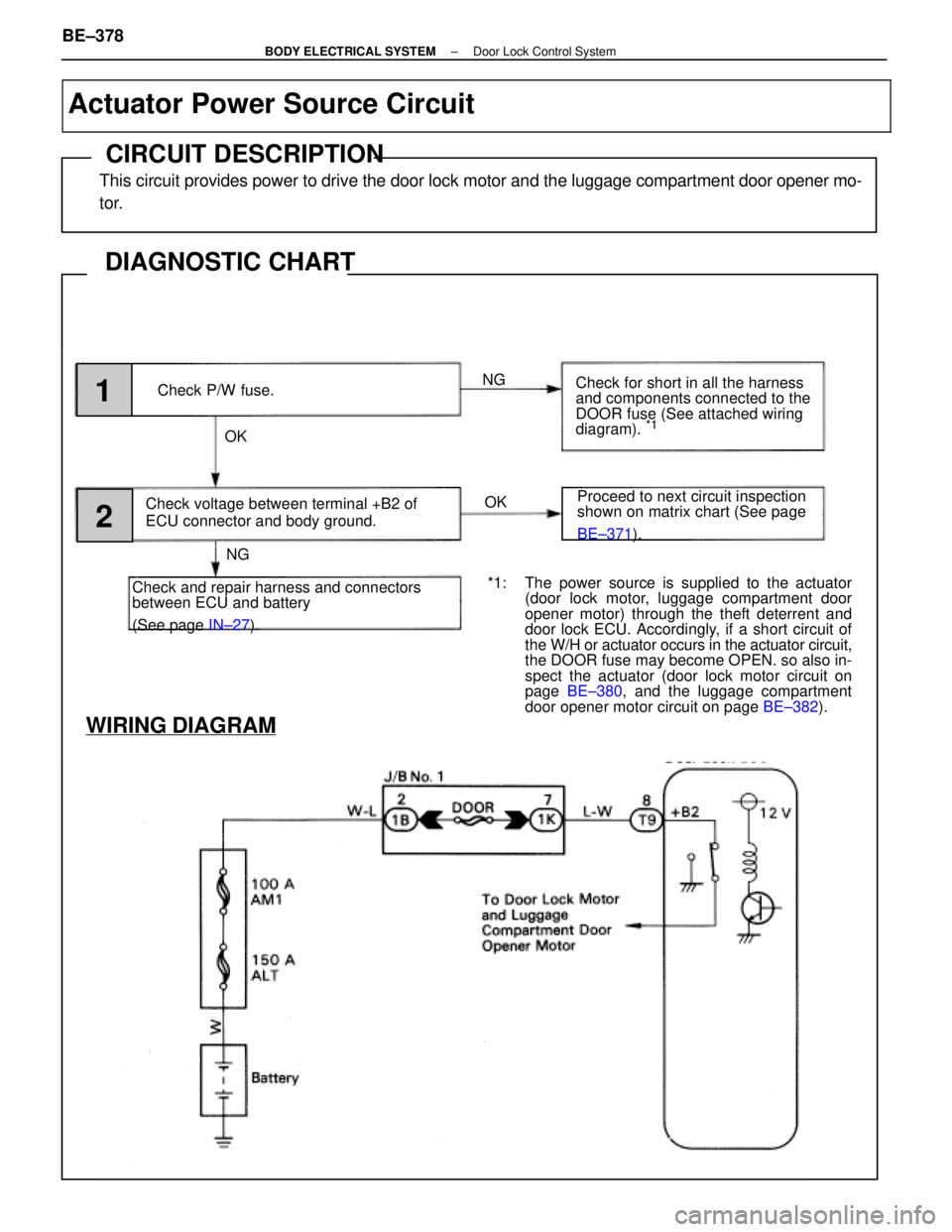
Check P/W fuse.
Check voltage between terminal +B2 of
ECU connector and body ground.
Check and repair harness and connectors
between ECU and battery
(See page IN±27). Check for short in all the harness
and components connected to the
DOOR fuse (See attached wiring
diagram).
*1
Proceed to next circuit inspection
shown on matrix chart (See page
BE±371
).
WIRING DIAGRAM
*1: The power source is supplied to the actuator
(door lock motor, luggage compartment door
opener motor) through the theft deterrent and
door lock ECU. Accordingly, if a short circuit of
the W/H or actuator occurs in the actuator circuit,
the DOOR fuse may become OPEN. so also in-
spect the actuator (door lock motor circuit on
page BE±380 , and the luggage compartment
door opener motor circuit on page BE±382).
Actuator Power Source Circuit
CIRCUIT DESCRIPTION
This circuit provides power to drive the door lock motor and the luggage com\
partment door opener mo-
tor.
DIAGNOSTIC CHART
BE±378±
BODY ELECTRICAL SYSTEM Door Lock Control System
WhereEverybodyKnowsYourName
Page 746 of 4087

OKNG
NGOK
*1: The power source is supplied to the actuator (doorlock motor, luggage compartment door opener mo-
tor) through the theft deterrent and door lock ECU.
Accordingly, if a short circuit of the W/H or actuator
occurs in the actuator circuit, the DOOR fusible link
may become OPEN, so also inspect the actuator
(door lock motor circuit on page BE±380, and the
luggage compartment door opener motor circuit on
page BE±382 ).
INSPECTION PROCEDURE
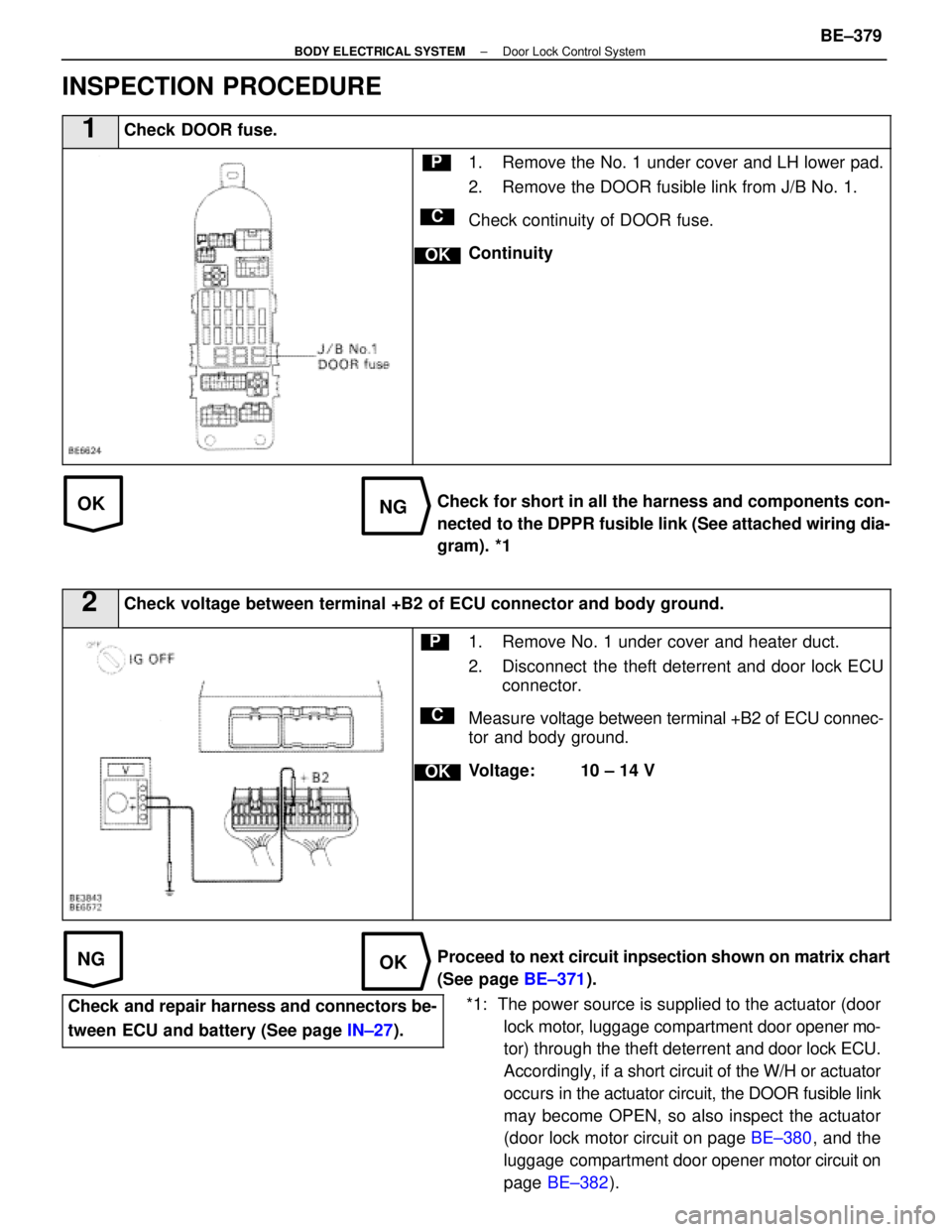
1Check DOOR fuse.
C
OK
P1. Remove the No. 1 under cover and LH lower pad.
2. Remove the DOOR fusible link from J/B No. 1.
Check continuity of DOOR fuse.
Continuity
Check for short in all the harness and components con-
nected to the DPPR fusible link (See attached wiring dia-
gram). *1
2Check voltage between terminal +B2 of ECU connector and body ground.
C
OK
P1. Remove No. 1 under cover and heater duct.
2. Disconnect the theft deterrent and door lock ECU connector.
Measure voltage between terminal +B2 of ECU connec-
tor and body ground.
Voltage: 10 ± 14 V
Proceed to next circuit inpsection shown on matrix chart
(See page BE±371).
Check and repair harness and connectors be-
tween ECU and battery (See page IN±27).
±
BODY ELECTRICAL SYSTEM Door Lock Control SystemBE±379
WhereEverybodyKnowsYourName
Page 784 of 4087

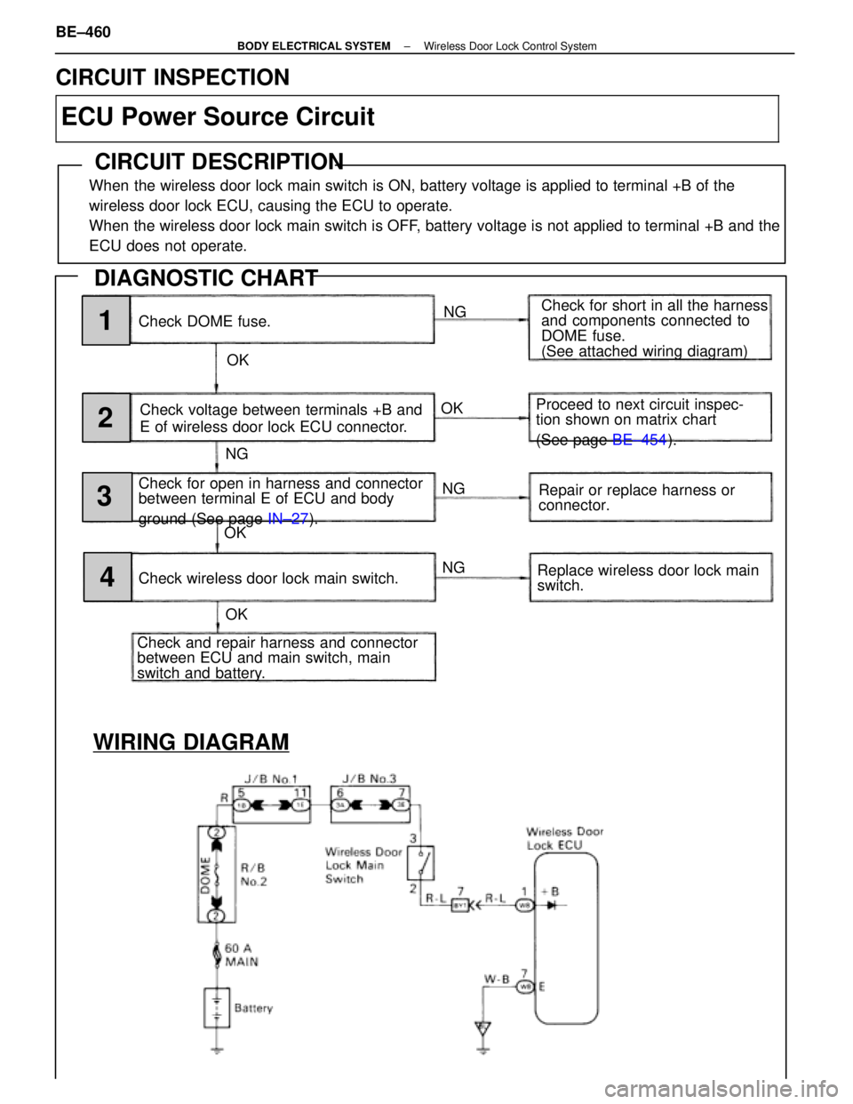
WIRING DIAGRAM
Check DOME fuse.NG
OK Check for short in all the harness
and components connected to
DOME fuse.
(See attached wiring diagram)
Check voltage between terminals +B and
E of wireless door lock ECU connector.
Check for open in harness and connector
between terminal E of ECU and body
ground (See page IN±27).
Check and repair harness and connector
between ECU and main switch, main
switch and battery. Check wireless door lock main switch. Proceed to next circuit inspec-
tion shown on matrix chart
(See page
BE±454).
Repair or replace harness or
connector.
Replace wireless door lock main
switch.
NG
NG
NG
OK
OK OK1
2
3
4
CIRCUIT INSPECTION
ECU Power Source Circuit
CIRCUIT DESCRIPTION
When the wireless door lock main switch is ON, battery voltage is applied to\
terminal +B of the
wireless door lock ECU, causing the ECU to operate.
When the wireless door lock main switch is OFF, battery voltage is not applied to terminal +B and the
ECU does not operate.
DIAGNOSTIC CHART
BE±460±
BODY ELECTRICAL SYSTEM Wireless Door Lock Control System
WhereEverybodyKnowsYourName
Page 785 of 4087

OKNG
NGOK
OKNG
OKNG
INSPECTION PROCEDURE
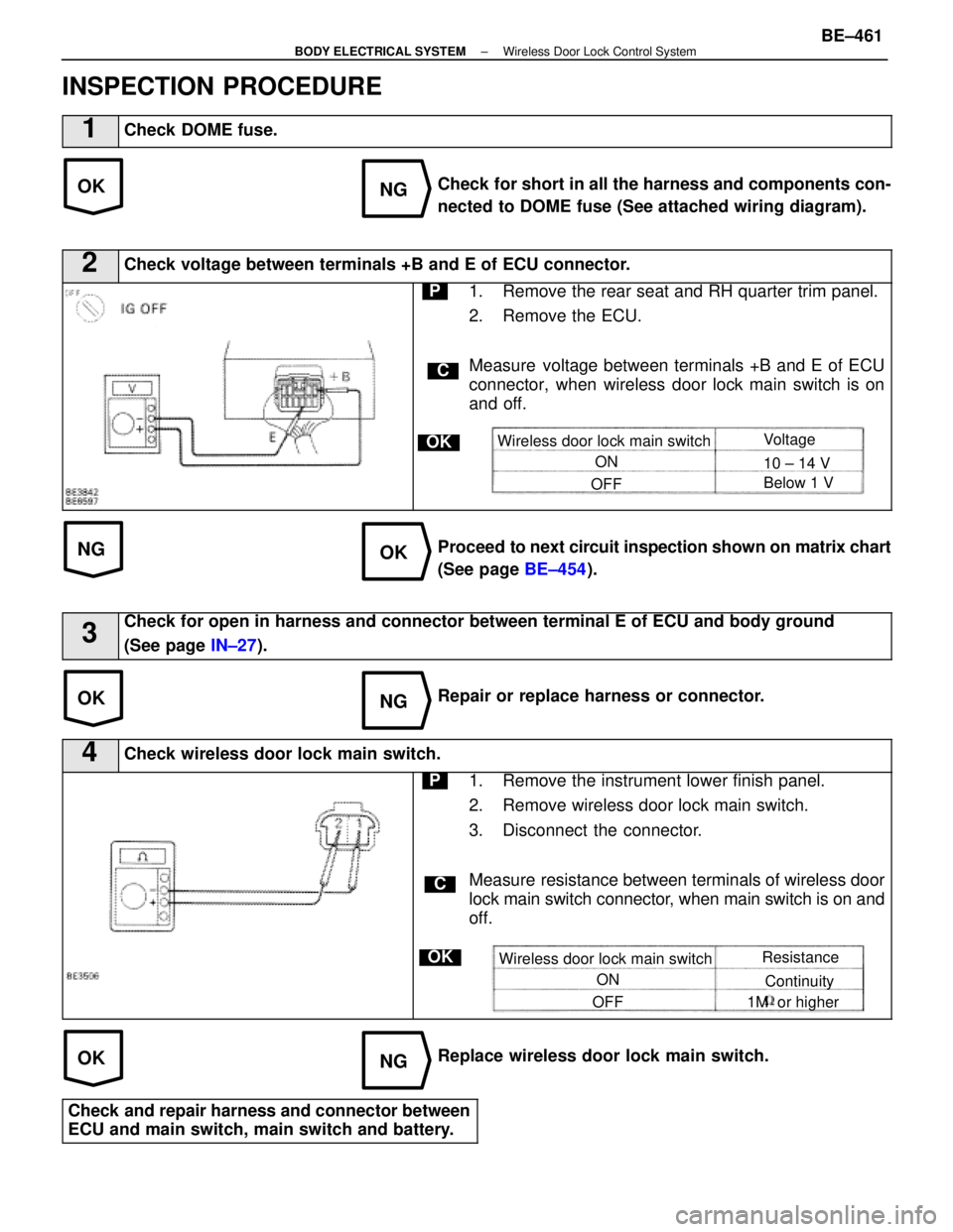
1Check DOME fuse.
Check for short in all the harness and components con-
nected to DOME fuse (See attached wiring diagram).
2Check voltage between terminals +B and E of ECU connector.
C
OK
P1. Remove the rear seat and RH quarter trim panel.
2. Remove the ECU.
Measure voltage between terminals +B and E of ECU
connector, when wireless door lock main switch is on
and off.
Wireless door lock main switchON
OFF Voltage
10 ± 14 V
Below 1 V
Proceed to
next circuit inspection shown on matrix chart
(See page BE±454).
3Check for open in harness and connector between terminal E of ECU and bo\
dy ground
(See page IN±27).
Repair or replace harness or connector.
4Check wireless door lock main switch.
C
OK
P1. Remove the instrument lower finish panel.
2. Remove wireless door lock main switch.
3. Disconnect the connector.
Measure resistance between terminals of wireless door
lock main switch connector, when main switch is on and
off.
Wireless door lock main switch
ON
OFF Resistance
Continuity
1M or higher
Replace wireless door lock main switch.
Check and repair harness and connector between
ECU and main switch, main switch and battery.
±
BODY ELECTRICAL SYSTEM Wireless Door Lock Control SystemBE±461
WhereEverybodyKnowsYourName
Page 932 of 4087
WIRING DIAGRAM
IN±33).
DTC24TRAC Sub±Throttle Actuator Circuit
CIRCUIT DESCRIPTION
The sub±throttle actuator operates in accordance with signals from the E\
CU, controlling the opening and
closing of the sub±throttle valve.
DTC No.DTC Detecting ConditionTrouble Area
24Open or short in sub±throttle actuator circuit
TRAC fuse
Open or short in BM circuit.
Sub±throttle actuator.
Open or short in sub±throttle actuatorcircuit.
ECU
DIAGNOSTIC CHARTDIAGNOSTIC CHART
BR±186±
BRAKE SYSTEM TRACTION CONTROL SYSTEM (TRAC)
WhereEverybodyKnowsYourName
Page 2736 of 4087
DIAGNOSTIC CHART
DIAGNOSTIC
CHART
Check for short in all the harness and
components connected to IGN fuse.
Check voltage of terminal M±REL.
Check for open in harness and connector
between battery and ECU.
Check and replace ECU.
Replace ignition switch.
Repair or replace harness or
connector.
Repair or replace harness or
connector.
Check for open and short in harness and
connector between terminal M REL and body
ground.
Replace EFT main relay.
Check voltage of terminal IGSW.
Check IGN fuse.
Check continuity between terminals E1 and
body ground.
Check voltage of ECU power source.
Proceed to next circuit inspection
shown on matrix chart (See page
TR±35
).
Check ignition switch.
Check EFT fuse.
Check EFT main relay.
Check and repair or harness or connector
between EFI fuse and battery.
Check for short in all the harness and
components connected to EFI fuse.
±
ENGINE TROUBLESHOOTING Circuit InspectionTR±125
WhereEverybodyKnowsYourName
Page 2741 of 4087
Back Up Power Source Circuit
CIRCUIT DESCRIPTION
Battery voltage is supplied to terminal BATT of the ECU even when the ignition switch is off for use by
the diagnostic code memory and air±fuel ratio adaptive control value mem\
ory, etc.
DIAGNOSTIC CHARTDIAGNOSTIC CHART
Check for short in all the harness and
components connected to EFI fuse.Check EFI fuse.
Check of terminal BATT.
Proceed to next circuit inspection shown on
matrix chart (See page TR±35).
Check operation for the back up.Check and replace ECU.
Check and repair harness or connector
between battery, EFI fuse and ECU.
WIRING DIAGRAM
TR±130±
ENGINE TROUBLESHOOTING Circuit Inspection
WhereEverybodyKnowsYourName
Page 2742 of 4087
OKNG
OKNG
YESNO
INSPECTION PROCEDURE
1Check EFI fuse.
C
OK
PRemove EFI fuse from R/B No.2.
Check continuity of EFI fuse.
Continuity
Check for short in all the harness and components con-
nected to EFI fuse (See attached wiring diagram).
2Check voltage between terminal BATT of engine & ECT ECU connector and body ground.
C
OK
PConnect the Check Harness A.
(See page TR±30).
Measure voltage between terminal BATT of engine &
ECT ECU connector and body ground.
Voltage: 10 ± 14 V
Check and repair harness or connector between engine
& ECT ECU and EFI fuse, EFI fuse and battery.
3Are the diagnostic codes still in the memory when the ignition switch is\
turned OFF?
Check and replace engine & ECT ECU.
Proceed to next circuit inspection shown on ma-
trix chart (See page TR±35).
±
ENGINE TROUBLESHOOTING Circuit InspectionTR±131
WhereEverybodyKnowsYourName