Page 94 of 4087
INSPECTION PROCEDURE
Check compressor
(1). Check compressor drive belt tension (See page AC-104).
(2). Check if the compressor does not lock during with engine started and blo\
wer switch and A/C switch ON.
Adjust drive belt tension or repair compressor.
Check compressor lock sensor.
Disconnect compressor lock sensor connector.
Measure resistance between terminals 1 and 2 of
compressor lock sensor connector.
Resistance:at 25°C (77°F) : 530 ±650 �
at 100°C (212°F) : 670 ±890�
Replace compressor lock sensor.
Check for open and short in harness and connectors between air conditioner
control assembly and compressor lock sensor (See page IN-27).
Repair or replace harness or connector.
Proceed to next circuit inspection shown on
matrix chart (See page AC-36).However,
when Diag. code 22 is displayed, check and
replace air conditioner control assembly.
±
AIR CONDITIONING SYSTEM TroubleshootingAC±55
WhereEverybodyKnowsYourName
Page 95 of 4087

Diag. Code 23Compressor Lock Sensor Circuit
CIRCUIT DESCRIPTION
The pressure switch sends the appropriate signals to the air conditioner co\
ntrol assembly when the air
conditioner refrigerant pressure drops too low or rises too high. When the air cond\
itioner control assem-
bly receives these signals, it outputs signals via the Engine & ECT ECU to switch off the compressor
relay and turns the magnet clutch off.
Code No.Diag. Code Detecting ConditionTrouble area
23
�Open in pressure sensor circuit.
� Abnormal refrigerant pressure.
below 206 kPa (2.1 kgf/cm
2, 30 psi)
over 2,650 kPa (27 kgf/cm2, 385 psi)
� Pressure switch.
� Harness or connector between pressure switch
and ECU. Refrigerant pipe line.
� ECU.
DIAGNOSTIC CHART
Check voltage between terminals LP of air
conditioner control assembly and body
ground.
Check pressure switch.
Check harness and connector between air
conditioner control assembly and pressure
switch and body ground
(See page IN-27).
Check and replace air conditioner control
assembly.
Proceed to next circuit inspection
shown on matrix chart (See page
AC-36 ).
Replace pressure switch
Repair or replace harness or
connector.
AC±56±
AIR CONDITIONING SYSTEM Troubleshooting
WhereEverybodyKnowsYourName
Page 121 of 4087
������������������\
������������������\
�
������������������\
�����������������
������������������\
������������������\
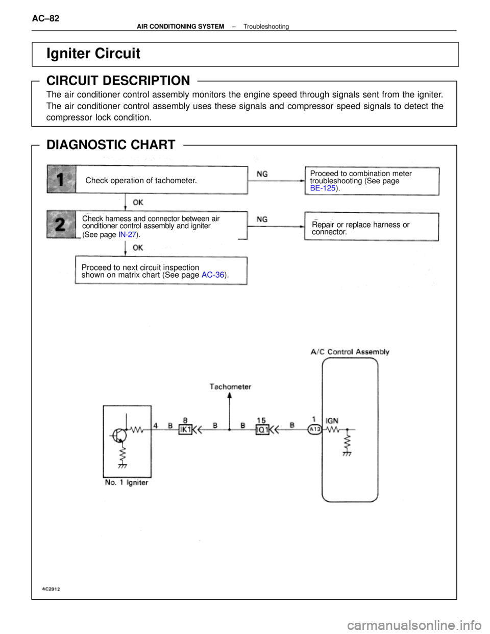
Igniter Circuit
CIRCUIT DESCRIPTION
The air conditioner control assembly monitors the engine speed through sign\
als sent from the igniter.
The air conditioner control assembly uses these signals and compressor speed signals to detect the
compressor lock condition.
DIAGNOSTIC CHART
WIRING DIAGRAM
Check operation of tachometer.
Check harness and connector between air
conditioner control assembly and igniter
(See page IN-27).
Proceed to combination meter
troubleshooting (See page
BE-125 ).
Proceed to next circuit inspection
shown on matrix chart (See page AC-36).
Repair or replace harness or
connector.
AC±82±
AIR CONDITIONING SYSTEM Troubleshooting
WhereEverybodyKnowsYourName
Page 157 of 4087
CONDENSER
ON±VEHICLE INSPECTION
1. INSPECT CONDENSER FINS FOR BLOCKAGE OR
DAMAGE
If the fins are clogged, wash them with water and dry with
compressed air.
NOTICE: Be careful not to damage the fins.
If the fins are bent, straighten them with a screwdriver or pli-
ers.
2. INSPECT CONDENSER AND FITTINGS FOR LEAKAGE Using a gas leak tester, check for leakage.
If there is leakage, check the tightening torque at the joints.
REMOVAL OF CONDENSER
1. RECOVER REFRIGERANT IN REFRIGERATION SYSTEMSee page AC±16
2. REMOVE BATTERY
3. REMOVE CONDENSER UPPER COVER AND RADIATOR FITTING BOLT
4. REMOVE UNDER COVER AND AIR FLOW COVER
5. REMOVE LIQUID TUBE AND SUCTION TUBE Remove two bolts and both tubes.
NOTICE: Cap open the fittings immediately to keep mois-
ture out of the system.
6. REMOVE CONDENSER Remove two nuts and lean the radiator backward, then re-
move the condenser.
AC±120
±
AIR CONDITIONING SYSTEM Condenser
WhereEverybodyKnowsYourName
Page 160 of 4087
8. PULL FLOOR CARPET DOWN AND REMOVECOMPUTER COVER
9. REMOVE EVAPORATOR COVER AND FOOT AIR DUCT BOLT
10. REMOVE EVAPORATOR (a) Remove six bolts and down the lower case.
(b) Pull and remove the evaporator.
(c) Pull out the evaporator sensor from the evaporator fins.
(d) Remove two bolts using a hexagon wrench and separate the evaporator and expansion valve.
INSPECTION OF EVAPORATOR
1. INSPECT FINS FOR BLOCKAGE
If the fins are clogged, clean them with compressed air.
NOTICE: Never use water to clean the evaporator.
2. INSPECT FITTINGS FOR CRACKS OR SCRATCHES Repair as necessary.
±
AIR CONDITIONING SYSTEM EvaporatorAC±123
WhereEverybodyKnowsYourName
Page 162 of 4087
HEATER RADIATOR
REMOVAL OF HEATER RADIATOR
1. SET TEMPERATURE CONTROL SWITCH TO MAX COOL
2. REMOVE A/C UNITSee page AC±107
3. REMOVE HATER RADIATOR
(a) Remove the two screws and the plate.
(b) Remove the two screws and the clamps.
(c) Pull the radiator out.
INSPECTION OF HEATER RADIATOR
INSPECT FINS FOR BLOCKAGE If the fins are clogged, clean them with compressed air.
INSTALLATION OF HEATER RADIATOR
1. INSTALL HEATER RADIATOR TO A/C UNIT(a) Put the radiator in the A/C until.
(b) Install the clamps with two screws.
(c) Install the plate with two screws.
2. INSTALL A/C UNIT
See page AC±108
±
AIR CONDITIONING SYSTEM Heater RadiatorAC±125
WhereEverybodyKnowsYourName
Page 173 of 4087
WATER TEMPERATURE SENSOR
REMOVAL OF WATER TEMPERATURE
SENSOR
1. REMOVE A/C UNITSee page AC±107
2. REMOVE SENSOR After taking off the clamp, take out the sensor.
INSPECTION OF WATER TEMPERATURE
SENSOR
See page AC±51
INSTALLATION OF WATER
TEMPERATURE SENSOR
1. INSTALL SENSOR TO A/C UNIT
Install the sensor with the clamp.
2. INSTALL A/C UNIT See page AC±108
PRESSURE SWITCH
INSPECTION OF PRESSURE SWITCH
See page AC±57
REMOVAL OF PRESSURE SWITCH
1. RECOVER REFRIGERANT IN REFRIGERANT SYSTEM
See page AC±16
2. REMOVE PRESSURE SWITCH
(a) Disconnect the connector.
(b) Remove the pressure switch from the liquid tube. HINT: Lock the switch mount on the tube with an open end
wrench, being careful not to deform the tube, and remove the
switch.
AC±136
±
AIR CONDITIONING SYSTEM Water Temperature Sensor, Pressure Switch
WhereEverybodyKnowsYourName
Page 174 of 4087
 Install the pressure switch to the liquid tube.
Specified torque: 10 NVm (100 kgf Vcm, 7 ft Vlbf)
HINT: Lock the switch mount on the t")
INSTALLATION OF PRESSURE SWITCH
1. INSTALL PRESSURE SWITCH
(a) Install the pressure switch to the liquid tube.
Specified torque: 10 NVm (100 kgf Vcm, 7 ft Vlbf)
HINT: Lock the switch mount on the tube with an open end
wrench, being careful not to deform the tube, and install the
switch.
(b) Connect the connector.
2. EVACUATE AIR IN REFRIGERATION SYSTEM AND CHARGE WITH REFRIGERANT
See page AC±17
Specified amount: 950 + 50 g (33.44 + 1.76 oz)
3. INSPECTION FOR LEAKAGE OF REFRIGERANT
Using a gas lead tester, check for leakage of refrigerant from
the pressure switch mount.
4. INSPECT A/C OPERATION
POWER TRANSISTOR
REMOVAL OF POWER TRANSISTOR
1. REMOVE GLOVE BOX
2. REMOVE POWER TRANSISTOR
(a) Disconnect connectors.
(b) Remove the two screws and the power transistor.
INSPECTION OF POWER TRANSISTOR
See page AC±79
INSTALLATION OF POWER
TRANSISTOR
1. INSTALL POWER TRANSISTOR
(a) Install power transistor with two screws.
(b) Connect connectors.
2. INSTALL GLOVE BOX
See page BO±112
±
AIR CONDITIONING SYSTEM Pressure Switch, Power TransistorAC±137
WhereEverybodyKnowsYourName
. Check compressor drive belt tension (See page AC-104).
(2). Check if the compressor does not lock during with engine started and blo\
wer switch and A/C swi")

 Remove six bolts and down the lower case.
(b) Pull and remove the ev")
 Remove the two screws and the plate.
(b)")
