Page 220 of 4087

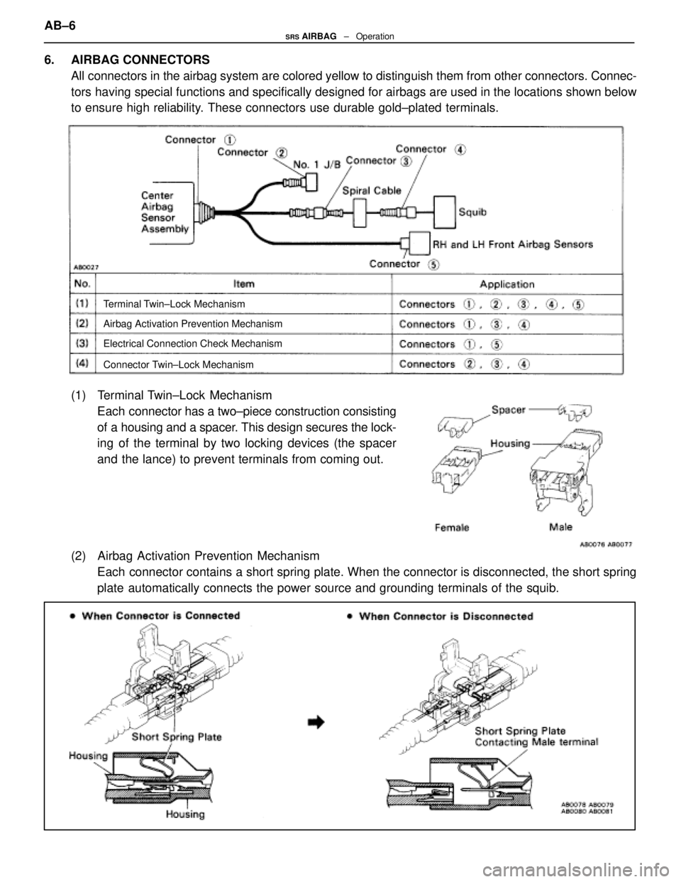
6. AIRBAG CONNECTORSAll connectors in the airbag system are colored yellow to distinguish them \
from other connectors. Connec-
tors having special functions and specifically designed for airbags are used\
in the locations shown below
to ensure high reliability. These connectors use durable gold±plated terminals.
Terminal Twin±Lock Mechanism
Airbag Activation Prevention Mechanism
Electrical Connection Check Mechanism
Connector Twin±Lock Mechanism
(1) Terminal Twin±Lock MechanismEach connector has a two±piece construction consisting
of a housing and a spacer. This design secures the lock-
ing of the terminal by two locking devices (the spacer
and the lance) to prevent terminals from coming out.
(2) Airbag Activation Prevention Mechanism Each connector contains a short spring plate. When the connector is disconnected, the short spring
plate automatically connects the power source and grounding terminals of the \
squib.
AB±6SRS AIRBAG ± Operation
WhereEverybodyKnowsYourName
Page 221 of 4087
HINT: The illustration shows connectors (3) and (4). Connector (1) has \
a short spring plate on the fe-
male terminal side, but the operating principle is the same.
(3) Electrical Connection Check MechanismThis mechanism is designed to electrically check if con-
nectors are connected correctly and completely.
The electrical connection check mechanism is designed
so that the connection detection pin connects with the
diagnosis terminals when the connector housing lock is
in the locked condition.
HINT: The illustration shows connector (5). Connector (1) also has the s\
ame operating principle.
AB±7SRS AIRBAG ± Operation
WhereEverybodyKnowsYourName
Page 222 of 4087

(4) Connector Twin±Lock MechanismWith this mechanism connectors (male and female connectors) are locked by \
two locking devices to
increase connection reliability. If the primary lock is incomplete, ribs interfere and prevent the seco\
nd-
ary lock.
When the vehicle is involved in a frontal collision in the hatched area (Fi\
g. 1) and the shock is larger than a prede-
termined level, the airbag is activated automatically. Safing sensors are designed to go on at a smaller decelera-
tion rate than the front and center airbag sensors. As illustrated in Fig. 2\
below, ignition is caused when current
flows to the squib, which happens when a safing sensor and a front airbag sen\
sor and/or the center airbag sen-
sor go on simultaneously.
When a deceleration force acts on the sensors, it causes the squib to ignite\
. Gas is then generated, increasing
the pressure inside the bag rapidly. The inflated bag breaks open the steering wheel pad. Bag inflation then
ends, and the gas is discharged through discharge holes provided behind the b\
ag. The bag becomes deflated
as a result.
AB±8SRS AIRBAG ± Operation
WhereEverybodyKnowsYourName
Page 228 of 4087

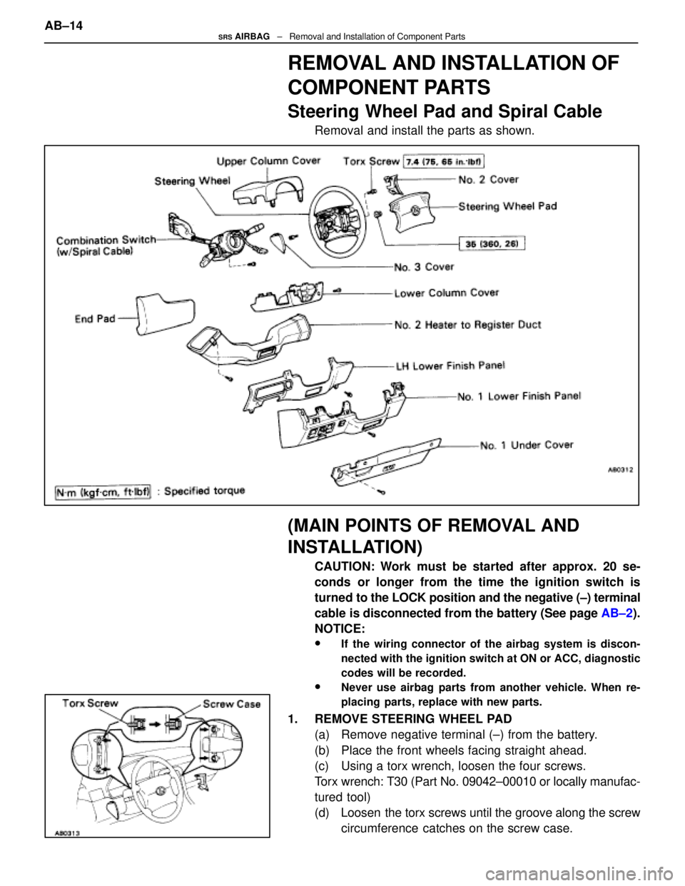
REMOVAL AND INSTALLATION OF
COMPONENT PARTS
Steering Wheel Pad and Spiral Cable
Removal and install the parts as shown.
(MAIN POINTS OF REMOVAL AND
INSTALLATION)
CAUTION: Work must be started after approx. 20 se-
conds or longer from the time the ignition switch is
turned to the LOCK position and the negative (±) terminal
cable is disconnected from the battery (See page AB±2).
NOTICE:
wIf the wiring connector of the airbag system is discon-
nected with the ignition switch at ON or ACC, diagnostic
codes will be recorded.
wNever use airbag parts from another vehicle. When re-
placing parts, replace with new parts.
1. REMOVE STEERING WHEEL PAD (a) Remove negative terminal (±) from the battery.
(b) Place the front wheels facing straight ahead.
(c) Using a torx wrench, loosen the four screws.
Torx wrench: T30 (Part No. 09042±00010 or locally manufac-
tured tool)
(d) Loosen the torx screws until the groove along the screwcircumference catches on the screw case.
AB±14
SRS AIRBAG
± Removal and Installation of Component Parts
WhereEverybodyKnowsYourName
Page 229 of 4087

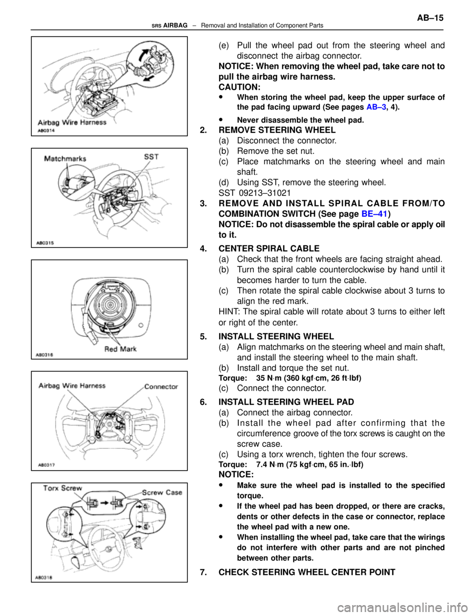
(e) Pull the wheel pad out from the steering wheel anddisconnect the airbag connector.
NOTICE: When removing the wheel pad, take care not to
pull the airbag wire harness.
CAUTION:
wWhen storing the wheel pad, keep the upper surface of
the pad facing upward (See pages AB±3, 4).
wNever disassemble the wheel pad.
2. REMOVE STEERING WHEEL
(a) Disconnect the connector.
(b) Remove the set nut.
(c) Place matchmarks on the steering wheel and mainshaft.
(d) Using SST, remove the steering wheel.
SST 09213±31021
3. REMOVE AND INSTALL SPIRAL CABLE FROM/TO COMBINATION SWITCH (See page BE±41)
NOTICE: Do not disassemble the spiral cable or apply oil
to it.
4. CENTER SPIRAL CABLE (a) Check that the front wheels are facing straight ahead.
(b) Turn the spiral cable counterclockwise by hand until it
becomes harder to turn the cable.
(c) Then rotate the spiral cable clockwise about 3 turns to align the red mark.
HINT: The spiral cable will rotate about 3 turns to either left
or right of the center.
5. INSTALL STEERING WHEEL (a) Align matchmarks on the steering wheel and main shaft,
and install the steering wheel to the main shaft.
(b) Install and torque the set nut.
Torque: 35 N Vm (360 kgf Vcm, 26 ft Vlbf)
(c) Connect the connector.
6. INSTALL STEERING WHEEL PAD (a) Connect the airbag connector.
(b) I n s t a l l t h e w heel pad after confirming that the
circumference groove of the torx screws is caught on the
screw case.
(c) Using a torx wrench, tighten the four screws.
Torque: 7.4 N Vm (75 kgf Vcm, 65 in. Vlbf)
NOTICE:
wMake sure the wheel pad is installed to the specified
torque.
wIf the wheel pad has been dropped, or there are cracks,
dents or other defects in the case or connector, replace
the wheel pad with a new one.
wWhen installing the wheel pad, take care that the wirings
do not interfere with other parts and are not pinched
between other parts.
7. CHECK STEERING WHEEL CENTER POINT AB±15
SRS AIRBAG
± Removal and Installation of Component Parts
WhereEverybodyKnowsYourName
Page 230 of 4087
Front Airbag Sensor
Remove and install the parts as shown.
(MAIN POINTS OF REMOVAL AND
INSTALLATION)
CAUTION: Work must be started after approx. 20 se-
conds or longer from the time the ignition switch is
turned to the LOCK position and the negative (±) terminal
cable is disconnected from the battery (See page AB±2).
NOTICE:
wIf the wiring connector of the airbag system is discon-
nected with the ignition switch at ON or ACC, diagnostic
codes will be recorded.
wNever use airbag parts from another vehicle. When
replacing parts, replace with new parts.
wNever reuse the sensor involved in a collision when the
airbag has deployed.
wNever repair a sensor in order to reuse it.
AB±16SRS AIRBAG ± Removal and Installation of Component Parts
WhereEverybodyKnowsYourName
Page 231 of 4087

INSTALL FRONT AIRBAG SENSOR
Install the sensor with the arrow on the sensor facing toward
the front of the vehicle.
Torque: 25 NVm (260 kgf Vcm, 19 ft Vlbf)
NOTICE:
wMake sure the sensor is installed to the specified torque.
wIf the sensor has been dropped, or there are cracks, dents
or other defects in the case, bracket or connector, replace
the sensor with a new one.
wThe sensor set bolts have been anti±rust treated. When
the sensor is removed, always replace the set bolts with
new ones.
wAfter installation, shake the sensor to check that there is
no looseness.
wThe front sensor is equipped with an electrical
connection check mechanism. Be sure to lock this
mechanism securely when connecting the connector. If
the connector is not securely locked, a malfunction code
will be detected by the diagnosis system.
wCheck that the dimensions of the body where the front
airbag sensor is installed match those in the body
dimension drawings on page BO±133.
(The airbag may malfunction, or may not work, if the
mounting angle or dimensions of the sensor mount
are not correct.) AB±17
SRS AIRBAG
± Removal and Installation of Component Parts
WhereEverybodyKnowsYourName
Page 233 of 4087

(MAIN POINTS OF REMOVAL AND
INSTALLATION)
CAUTION: Work must be started after approx. 20 se-
conds or longer from the time the ignition switch is
turned to the LOCK position and the negative (±) terminal
cable is disconnected from the battery (See page AB±2).
NOTICE:
wDo not open the cover or the case of the ECU and various
computers unless absolutely necessary. (If the IC termi-
nals are touched, the IC may be destroyed by static elec-
tricity.)
wNever use airbag parts from another vehicle. When
replacing parts, replace with new parts.
wNever reuse the center airbag sensor assembly involved
in a collision when the airbag has deployed.
wNever repair a sensor in order to reuse it.
REMOVE AND INSTALL CENTER
AIRBAG SENSOR ASSEMBLY
(a) Using a torx wrench, loosen and tighten the three screws.
Torx wrench: T40 (Part No. 09042±00020 or locally manufac-
tured tool)
Torque: 13 N Vm (130 kgf Vcm, 9 ft Vlbf)
NOTICE:
wMake sure the sensor assembly is installed to the speci-
fied torque.
wIf the sensor assembly has been dropped, or there are
cracks, dents or other defects in the case, bracket or
connector, replace the sensor assembly with a new one.
wWhen installing the sensor assembly, take care that the
airbag wiring does not interfere with other parts and is
not pinched between other parts.
wAfter installation, shake the sensor assembly to check
that there is no looseness.
(b) Disconnect the connector. AB±19
SRS AIRBAG
± Removal and Installation of Component Parts
WhereEverybodyKnowsYourName