Page 106 of 4087
 Remove console upper panel.(See page BO-111 ).
(2) Remove A/C control assembly with
connectors still co")
Check voltage between terminals TPM and SG of air conditioner control
assembly connector.
(1) Remove console upper panel.(See page BO-111 ).
(2) Remove A/C control assembly with
connectors still connected.
(3) Turn ignition switch ON.
In addition, as the air outlet servomotor is moved
from REC side to FRS side, the voltage decreases
gradually without interruption.
Proceed to next circuit inspection shown on matrix chart
(See page AC-36).However, when Diag. code 32 or 42 is dis-
played, check and replace air conditioner control assembly.
Check air outlet damper position sensor.
(1) Remove heater unit. (See page AC-127)
(2) Disconnect air outlet servomotor assembly
connector.
Measure resistance between terminals S5 and SG of
air outlet servomotor assembly connector.
Resistance: 4.7~7.2 k �
While operating air outlet servomotor as in the
procedure on page AC-69, measure resistance
between terminals TP1 and SG of air outlet servo-
motor assembly connector.
Resistance:
As the air inlet servomotor moves from DEF side
to FACE side, the resistance decreases gradually
without interruption.
Replace air outlet servomotor assembly.
Check for open and short in harness and connector between air conditioner
control assembly and air outlet servomotor assembly (See page IN-27).
Repair or replace harness or connector.
Check and replace air conditioner control assembly.
INSPECTION PROCEDURE
±
AIR CONDITIONING SYSTEM TroubleshootingAC±67
WhereEverybodyKnowsYourName
Page 110 of 4087
 Remove console upper panel.(See pageBO-111 ).
(2) Remove A/C control assembly with connec±
tors still")
Check voltage between terminals IG+ and E of air conditioner control
assembly connector.
(1) Remove console upper panel.(See pageBO-111 ).
(2) Remove A/C control assembly with connec±
tors still connected.
(3) Turn ignition switch ON.
Measure voltage between terminals IG+ and E of air
conditioner control assembly.
Voltage: 10 ±14 V
Proceed to next circuit inspection shown on matrix
chart (See page AC-36).
Check continuity between terminals E of air conditioner control assem-
bly and body ground.
Measure resistance between terminals E of air condi-
tioner control assembly and body ground.
Resistance:�1 �� or less
Repair or replace harness or connector.
Remove HTR fuse from J/B No. 1.
Check continuity of HTR fuse
Continuity
Check HTR fuse.
Check for short in all the harness and
components connected to the HTR fuse
See attached wiring diagram).
Check and repair harness and connector between air conditioner control \
assembly and battery.
INSPECTION PROCEDURE
±
AIR CONDITIONING SYSTEM TroubleshootingAC±71
WhereEverybodyKnowsYourName
Page 112 of 4087
Check voltage between terminals ACC of air conditioner control
assembly connector and body ground.
(1) Remove console upper panel.(See page BO-111 ).
(2) Remove A/C control assembly with connec±
tors still connected.
(3) Turn ignition switch ON.
Measure voltage between terminals ACC of air
conditioner control assembly connector and body
ground.
Voltage: 10 ± 14 V
Proceed to next circuit inspection shown on matrix
chart (See page AC-36).
Check RADIO No. 2 fuse.
Remove RADIO No. 2 fuse from J/B No. 1.
Check continuity of RADIO No. 2 fuse.
Continuity.
Check for short in all the harness and
components connected to the RADIO No. 2
fuse (See attached wiring diagram).
Check and repair harness and connector between air conditioner control \
assembly and battery.
INSPECTION PROCEDURE
±
AIR CONDITIONING SYSTEM TroubleshootingAC±73
WhereEverybodyKnowsYourName
Page 113 of 4087
������������������\
������������������\
�
������������������\
�����������������
������������������\
������������������\
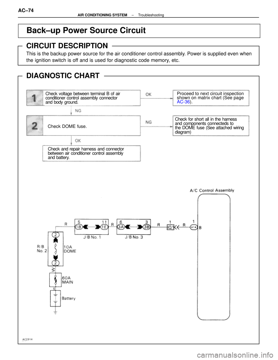
Back±up Power Source Circuit
CIRCUIT DESCRIPTION
This is the backup power source for the air conditioner control assembly. Power is supplied even when
the ignition switch is off and is used for diagnostic code memory, etc.
DIAGNOSTIC CHART
WIRING DIAGRAM
Check voltage between terminal B of air
conditioner control assembly connector
and body ground.
Check DOME fuse.
Proceed to next circuit inspection
shown on matrix chart (See page
AC-36
).
Check and repair harness and connector
between air conditioner control assembly
and battery.
Check for short all in the harness
and components connecteds to
the DOME fuse (See attached wiring
diagram)
AC±74±
AIR CONDITIONING SYSTEM Troubleshooting
WhereEverybodyKnowsYourName
Page 116 of 4087
 Remove console upper panel.(See page BO-111 ).
(2) Remove A/C control assembly with connec±")
Check voltage between terminals HR of air conditioner control assem-
bly connector and body ground.
(1) Remove console upper panel.(See page BO-111 ).
(2) Remove A/C control assembly with connec±
tors still connected.
Proceed to next circuit inspection shown on ma-
trix chart (See page AC-36).
Check heater main relay.
Check continuity between each pair of terminals of
heater main relay shown below.
Measure voltage between terminals HR of air condi-
tioner control assembly and body ground when
ignition switch is on and off.
(1) Apply battery voltage between terminals 1
and 3
(2) Check continuity between each pair of ter±minal shown below.
Replace heater main relay.
Remove HTR fuse from J/B No. 1.
Check continuity of HTR fuse
Continuity
Check for short in all the harness and
components connected to the HTR fuse
See attached wiring diagram).
Check and repair harness and connector between air conditioner control \
assembly and battery.
INSPECTION PROCEDURE
±
AIR CONDITIONING SYSTEM TroubleshootingAC±77
WhereEverybodyKnowsYourName
Page 126 of 4087
 Remove console upper panel.(See page BO-111 ).
(2) Remove A/C control assembly with connec±")
Check voltage between terminals MGC of air conditioner control assem-
bly connector and body ground.
(1) Remove console upper panel.(See page BO-111 ).
(2) Remove A/C control assembly with connec±
tors still connected.
(3) Start the engine.
Check voltage between terminals MGC of air condi-
tioner control assembly connector and body ground
when magnetic clutch is on and off by A/C
switch.
Go to step (7).
Check voltage between terminals MGC of air conditioner control assem-
bly harness side connector and body ground.
(1) Disconnect air conditioner control assemblyconnector.
(3) Turn ignition switch ON.
Check voltage between terminals MGC of air condi-
tioner control assembly harness side connector and
body ground.
Voltage: 4 ± 6 V
Check and replace air conditioner control
assembly.
Check for open and short in harness and connector between
air conditioner control assembly and engine & ECT ECU (See page IN-27).
Repair or replace harness or connector.
Check and replace engine & ECT ECU.
±
AIR CONDITIONING SYSTEM TroubleshootingAC±87
WhereEverybodyKnowsYourName
Page 127 of 4087
 Apply battery voltage between termin")
Check magnetic clutch relay.
Remove magnetic clutch relay from R/B No. 2
Check continuity between each pair of terminals
shown below of magnetic clutch relay.
(1) Apply battery voltage between terminals 2 and 3
(2) Check continuity between terminals 4 and 1
Replace magnetic relay.
(1) Remove engine & ECT ECU with connectors still connected.
(2) Turn ignition switch ON.
(1) Push one of the fan speed control switches
(Lo, Med or Hi).
(2) Measure voltage between terminal ACMG of engine & ECT ECU connector and body
ground.
Go to step (10).
Check voltage between terminal ACMG of engine & ECT ECU and
body ground.
Check for open and short in harness and connector between engine &
ECT ECU and battery (See page IN-27).
Repair or replace harness or connector.
Check and replace engine & ECT ECU.
Check for open and short in harness and connector between air conditioner control
assembly and compressor relay, compressor relay and battery (See page IN-27).
Repair or replace harness or connector.
Check and replace air conditioner control a ssembly.
AC±88±
AIR CONDITIONING SYSTEM Troubleshooting
WhereEverybodyKnowsYourName
Page 131 of 4087
Check voltage between terminal SET 1 ~ 5 and SG of A/C control
assembly
(1) Remove A/C control assembly with connec-tors.(See page AC-138).
(2) Turn ignition switch ON.
Measure voltage between terminals SET 1 ~ 5 and
SG of temp. control switch is turned from most left to
right position.
for USA spec.for Canada spec.
Proceed to next circuit inspection shown on
matrix chart. ( See page AC-36).
Go to step (2).
INSPECTION PROCEDURE
±
AIR CONDITIONING SYSTEM TroubleshootingAC±93
WhereEverybodyKnowsYourName
 Remove console upper panel.(See page BO-111 ).
(2) Remove A/C control assembly with connec±
t")
 Remove A/C control assembly with connec-tors.(See page AC-138).
(2) Turn ignition switch ON.
Measure voltage between t")