Page 296 of 4087

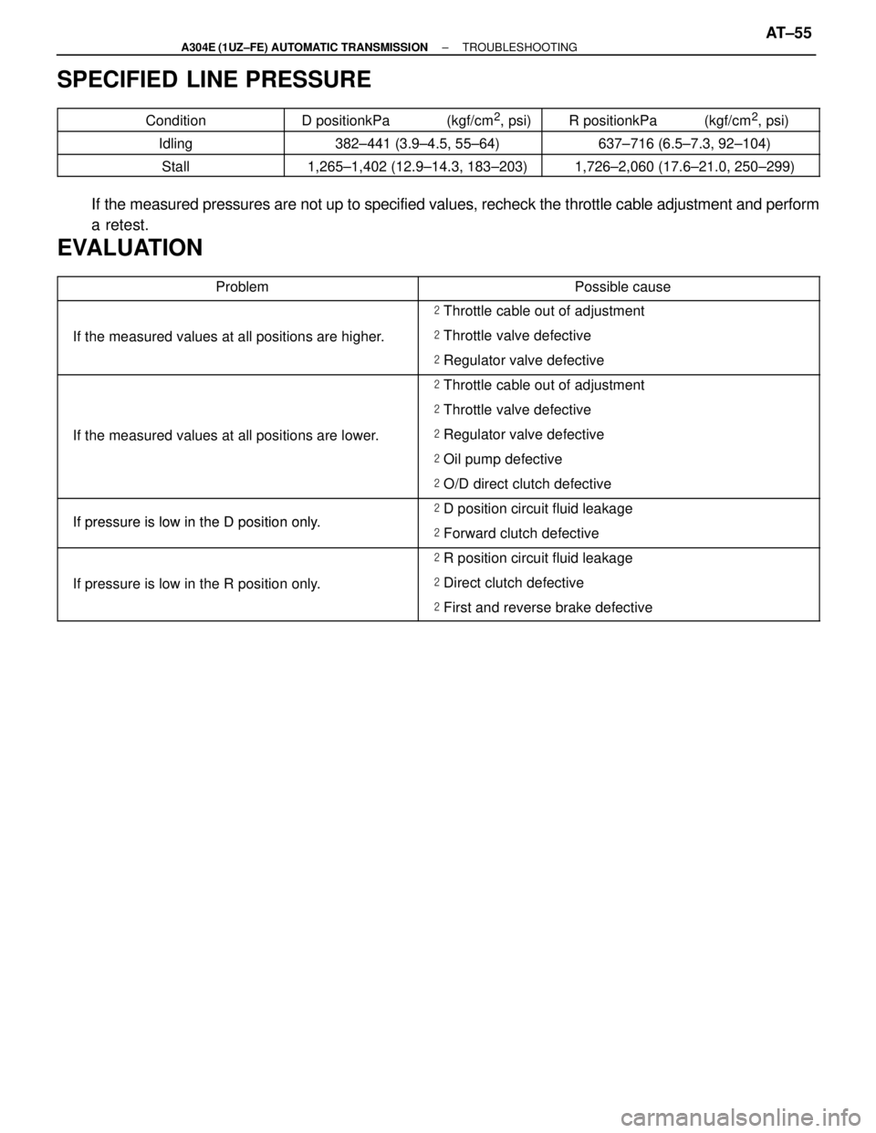
SPECIFIED LINE PRESSURE
����������� �����������
Condition
������������� �������������
D positionkPa (kgf/cm2, psi)
�������������� ��������������
R positionkPa (kgf/cm2, psi)����������� �
����������
�����������Idling
������������� �
������������
�������������382±441 (3.9±4.5, 55±64)
�������������� �
�������������
��������������637±716 (6.5±7.3, 92±104)����������� �
����������
�����������Stall
������������� �
������������
�������������1,265±1,402 (12.9±14.3, 183±203)
�������������� �
�������������
��������������1,726±2,060 (17.6±21.0, 250±299)
If the measured pressures are not up to specified values, recheck the thro\
ttle cable adjustment and perform
a retest.
EVALUATION
����������������� �����������������Problem������������������\
� ������������������\
�Possible cause
����������������� �����������������������������������\
� ������������������\
��
Throttle cable out of adjustment����������������� �����������������If the measured values at all positions are higher.������������������\
� ������������������\
�� Throttle valve defective����������������� �
����������������
�����������������
������������������\
�
������������������\
�
������������������\
��
Regulator valve defective
����������������� �����������������������������������\
� ������������������\
�� Throttle cable out of adjustment
����������������� �����������������������������������\
� ������������������\
�� Throttle valve defective
����������������� �����������������If the measured values at all positions are lower.������������������\
� ������������������\
�� Regulator valve defective
����������������� �����������������������������������\
� ������������������\
�� Oil pump defective
����������������� �����������������������������������\
� ������������������\
�� O/D direct clutch defective
����������������� �����������������
Ifpressure is low in the Dposition only
������������������\
� ������������������\
�� D position circuit fluid leakage����������������� �����������������If pressure is low in the D position only.������������������\
� ������������������\
�� Forward clutch defective����������������� �
����������������
�����������������
������������������\
�
������������������\
�
������������������\
��
R position circuit fluid leakage
����������������� �����������������If pressure is low in the R position only.������������������\
� ������������������\
�� Direct clutch defective
����������������� �����������������������������������\
� ������������������\
�� First and reverse brake defective
±
A304E (1UZ±FE) AUTOMATIC TRANSMISSION TROUBLESHOOTINGAT±55
WhereEverybodyKnowsYourName
Page 298 of 4087
(f) Fully apply the parking brake and chock the 4 wheels.
(g) Start the engine and check idling RPM.
(h) Keep your left foot pressed firmly on the brake pedal and shift into D p\
osition.
(i) Measure the accumulator back pressure.
(j) With the conditions the same as in (h), ground the other probe of the test\
lead which has one end insertedinto the terminal SLN of the ECM harness side connector, then measure the accumulator back pressure
again.
±
A304E (1UZ±FE) AUTOMATIC TRANSMISSION TROUBLESHOOTINGAT±57
WhereEverybodyKnowsYourName
Page 322 of 4087

DTC46No. 4 Solenoid Valve Circuit (For Accumula-
tor Back Pressure Modulation)
CIRCUIT DESCRIPTION
The No. 4 solenoid valve controls the hydraulic pressure acting on the
brakes and clutches of the planetary gear units when gears are shifted and
performs smooth gear shifting.
The ECM determines optimum operating pressure according to the signals
from the throttle position sensor, vehicle speed sensor and O/D clutch
speed sensor and controls the volume of current flow to the solenoid valve.
The amount of electric current to the solenoid is controlled by the (*) \
duty
ratio of ECM out put signals, causing momentary change to the hydraulic
pressure acting on the clutches during gear shifting.
When the duty ratio is high, the hydraulic pressure acting on the clutch\
es
is low.
(*) Duty Ratio
The duty ration is the ration of the period of continuity in one cycle. For\
example, if A is the period of continuity
in one cycle, and B is the period of non±continuity, then
DTC No.DTC Detecting ConditionTrouble Area
46
All conditions below are detected for 1 sec. or more.
2trip detection logic*
(a) ECM outputs duty signal to No. 4 solenoid in 90%
or higher duty ratio.
(b) Current to No. 4 solenoid:330 � 100 Ma OR LESS
(O/D OFF indicator light doesn't blink)
� No. 4 solenoid valve.
� Harness or connector between No. 4 sole-
noid valve and ECM
� ECM
*: See page AT±62.
Reference Reference
� Waveform between terminals SLN± and E
1when engine is idling. �
Waveform between terminals SLN± and E1 during shift
change.
AT±82±
A304E (1UZ±FE) AUTOMATIC TRANSMISSION TROUBLESHOOTING
WhereEverybodyKnowsYourName
Page 343 of 4087
OKNG
OKNG
OKNG
INSPECTION PROCEDURE
1Main throttle position signal check.
C
OK
Hint
PTurn ignition switch ON (Do not start the engine).
Check voltage at the terminal T
T of the DLC2 while grad-
ually depressing the accelerator pedal from the fully
closed position to the fully opened position.
Voltage changes from 0 V to 8 V by stages.
Do not depress the brake pedal during this test. The
voltage will stay at 0 V if depressed.
Proceed to next circuit inspection shown on matrix chart
(See page AT±66).
2Check throttle position sensor.
See engine troubleshooting section in EG section.
Replace throttle position sensor.
3Check harness and connector between ECM and throttle position sensor (S\
ee page IN±33).
Repair or replace harness or connector.
Check and replace ECM.
±
A304E (1UZ±FE) AUTOMATIC TRANSMISSION TROUBLESHOOTINGAT±103
WhereEverybodyKnowsYourName
Page 348 of 4087
AT±66BE
IN±33
WIRING DIAGRAM
Stop Light Switch Circuit
CIRCUIT DESCRIPTION
The purpose of this circuit is to prevent the engine from stalling, while d\
riving in lockup condition, when
brakes are suddenly applied.When the brake pedal is operated, this switch sends a signal to ECM. Then
the ECM cancels operation of the lockup clutch while braking is in progress\
.
DIAGNOSTIC CHARTDIAGNOSTIC CHART
AT±108±
A304E (1UZ±FE) AUTOMATIC TRANSMISSION TROUBLESHOOTING
WhereEverybodyKnowsYourName
Page 349 of 4087
OKNG
OKNG
OKNG
INSPECTION PROCEDURE
1Check operation of stop light.
Check if the stop lights go on and off normally when the brake pedal is operated and released.C
Check and repair stop light circuit (See BE section).
2Check stop light signal.
C
OK
1. Connect voltmeter to the terminals TT and E1 of the
DLC2.
2. Turn ignition switch ON (Do not start the engine).
3. Fully depress the accelerator pedal until the volt- meter indicates 8 V and hold it.
4. Depress and release the brake pedal and check the
voltage.
Proceed to next circuit inspection shown on matrix chart
(See page AT±66).
3Check harness and connector between ECM and stop light switch (See page\
IN±33).
Repair or replace harness or connector.
Check and replace ECM.
±
A304E (1UZ±FE) AUTOMATIC TRANSMISSION TROUBLESHOOTINGAT±109
WhereEverybodyKnowsYourName
Page 360 of 4087
IN±33
WIRING DIAGRAM
TT Terminal Circuit
CIRCUIT DESCRIPTION
Checks of ECM input and output signals related to the throttle position sensor\
brakes, shift position and
other circuits can be performed by measuring the voltages at terminal T
T of the DLC1.
DIAGNOSTIC CHARTDIAGNOSTIC CHART
AT±120±
A304E (1UZ±FE) AUTOMATIC TRANSMISSION TROUBLESHOOTING
WhereEverybodyKnowsYourName
Page 366 of 4087

������������ ������������
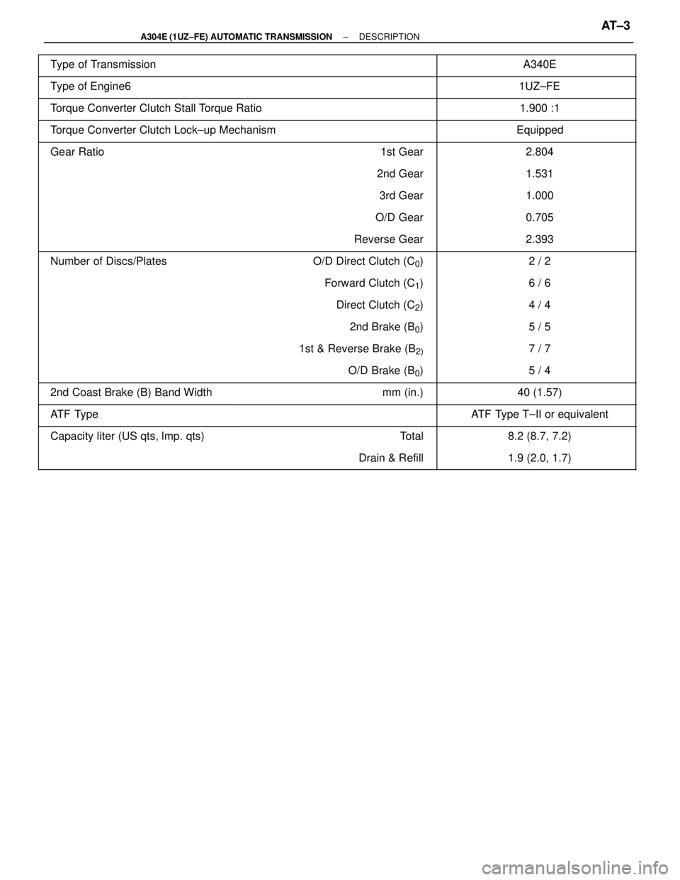
Type of Transmission������������� �������������������������� �������������A340E
������������������\
������ ������������������\
������Type of Engine61UZ±FE
������������������\
������ �
������������������\
�����
������������������\
������Torque Converter Clutch Stall Torque Ratio1.900 :1
������������������\
������ ������������������\
������Torque Converter Clutch Lock±up MechanismEquipped
������������ ������������Gear Ratio������������� �������������1st Gear������������� �������������2.804
������������ ������������������������� �������������2nd Gear������������� �������������1.531������������ �
�����������
������������
������������� �
������������
�������������3rd Gear
������������� �
������������
�������������1.000
������������ ������������������������� �������������O/D Gear������������� �������������0.705
������������ ������������������������� �������������Reverse Gear������������� �������������2.393
������������ �
�����������Number of Discs/Plates������������� �
������������O/D Direct Clutch (C0)������������� �
������������2 / 2������������ �
�����������
������������
������������� �
������������
�������������Forward Clutch (C1)
������������� �
������������
�������������6 / 6
������������ ������������������������� �������������Direct Clutch (C2)������������� �������������4 / 4
������������ ������������������������� �������������2nd Brake (B0)������������� �������������5 / 5������������ �
�����������
������������
������������� �
������������
�������������1st & Reverse Brake (B2)
������������� �
������������
�������������7 / 7
������������ ������������������������� �������������O/D Brake (B0)������������� �������������5 / 4
������������ ������������2nd Coast Brake (B) Band Width������������� �������������mm (in.)������������� �������������40 (1.57)
������������ ������������ATF TypeATF Type T±II or equivalent������������ �
�����������
������������Capacity liter (US qts, lmp. qts)
������������� �
������������
�������������Total
������������� �
������������
�������������8.2 (8.7, 7.2)
������������ ������������������������� �������������Drain & Refill������������� �������������1.9 (2.0, 1.7)
±
A304E (1UZ±FE) AUTOMATIC TRANSMISSION DESCRIPTIONAT±3
WhereEverybodyKnowsYourName