Page 125 of 4087
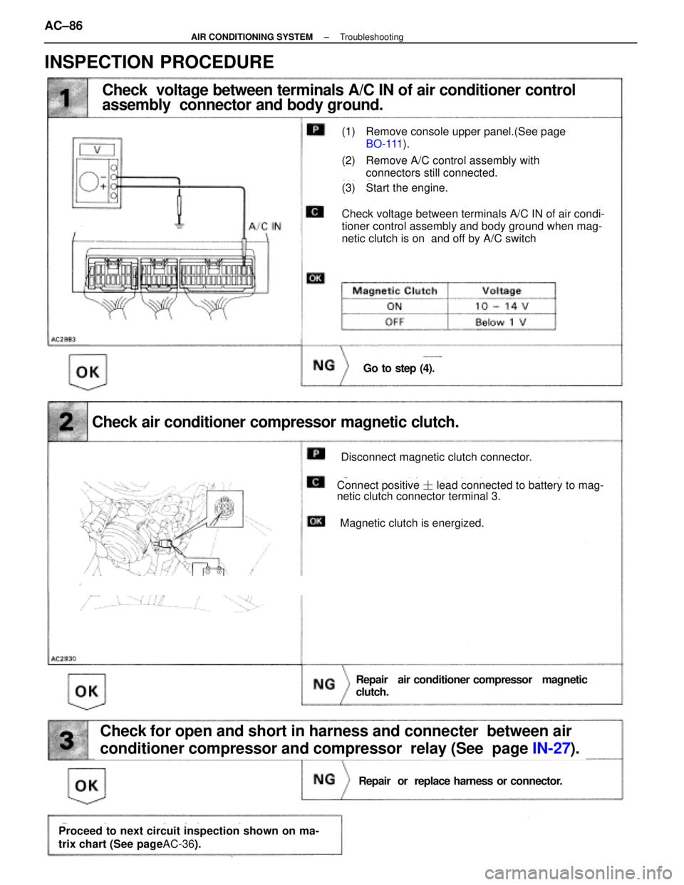
Check voltage between terminals A/C IN of air conditioner control
assembly connector and body ground.
(1) Remove console upper panel.(See pageBO-111 ).
(2) Remove A/C control assembly with
connectors still connected.
(3) Start the engine.
Check voltage between terminals A/C IN of air condi-
tioner control assembly and body ground when mag-
netic clutch is on and off by A/C switch
Go to step (4).
Check air conditioner compressor magnetic clutch.
Disconnect magnetic clutch connector.
Connect positive � lead connected to battery to mag-
netic clutch connector terminal 3.
Magnetic clutch is energized.
Repair air conditioner compr essor magnetic
clutch.
Check for open and short in harness and connecter between air
conditioner compressor and compressor relay (See page IN-27).
Repair or replace harness or connector.
Proceed to next circuit inspection shown on ma-
trix chart (See page AC-36).
INSPECTION PROCEDURE
AC±86±
AIR CONDITIONING SYSTEM Troubleshooting
WhereEverybodyKnowsYourName
Page 127 of 4087
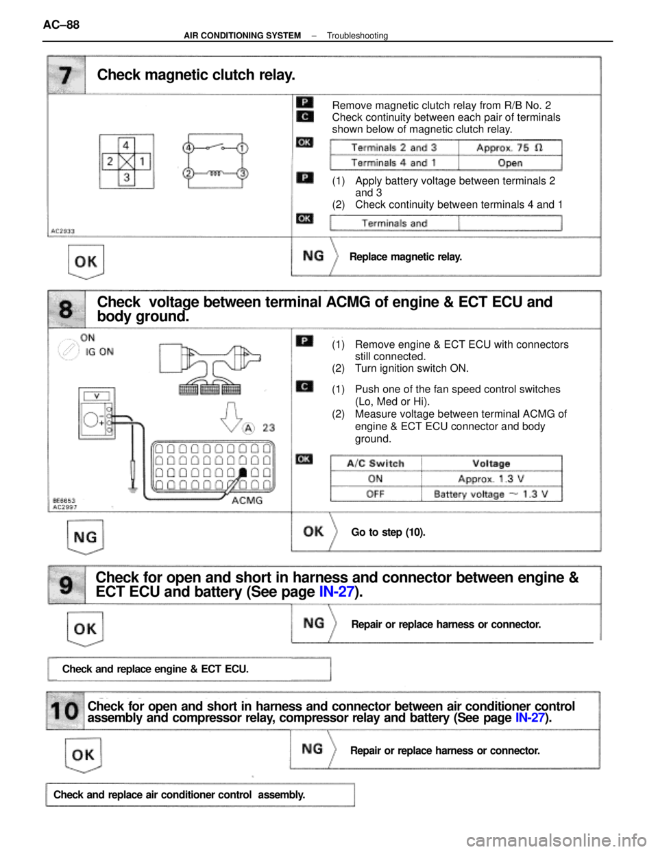
Check magnetic clutch relay.
Remove magnetic clutch relay from R/B No. 2
Check continuity between each pair of terminals
shown below of magnetic clutch relay.
(1) Apply battery voltage between terminals 2 and 3
(2) Check continuity between terminals 4 and 1
Replace magnetic relay.
(1) Remove engine & ECT ECU with connectors still connected.
(2) Turn ignition switch ON.
(1) Push one of the fan speed control switches
(Lo, Med or Hi).
(2) Measure voltage between terminal ACMG of engine & ECT ECU connector and body
ground.
Go to step (10).
Check voltage between terminal ACMG of engine & ECT ECU and
body ground.
Check for open and short in harness and connector between engine &
ECT ECU and battery (See page IN-27).
Repair or replace harness or connector.
Check and replace engine & ECT ECU.
Check for open and short in harness and connector between air conditioner control
assembly and compressor relay, compressor relay and battery (See page IN-27).
Repair or replace harness or connector.
Check and replace air conditioner control a ssembly.
AC±88±
AIR CONDITIONING SYSTEM Troubleshooting
WhereEverybodyKnowsYourName
Page 159 of 4087
EVAPORATOR
REMOVAL OF EVAPORATOR
1. DISCONNECT NEGATIVE (±) CABLE FROM BATTERY
2. RECOVER REFRIGERANT IN REFRIGERATION SYSTEMSee page AC±16
3. REMOVE ABS ACTUATOR
See page BR±48
4. REMOVE LIQUID TUBE AND SUCTION TUBE Remove two bolts and both tubes.
5. REMOVE EQUALIZER TUBE FROM EPR
Remove the bole and the tube.
NOTICE: Cap the open fittings immediately to keep mois-
ture out of the system.
6. REMOVE UNDER COVER GLOVE BOX AND SIDE AIR DUCT
7. DISCONNECT CONNECTORS AND REMOVE POWER STEERING RELAY BOX COOLING FAN COMPUTER AND
TRC COMPUTER
AC±122
±
AIR CONDITIONING SYSTEM Evaporator
WhereEverybodyKnowsYourName
Page 442 of 4087
7. REMOVE WIND DEFLECTOR(a) Slide the drive cable backward.
(b) Remove four screws and the deflector.
8. REMOVE CABLE GUIDE CASING (a) Remove two screws and the guide rail cover.
(b) Remove two screws from the drive rail.
(c) Slide the drive cable forward.
(d) Pull down the roof handlining.
(e) Disconnect front side of the drain hose.
HINT: Disconnect the drain hose from the sliding roof
housing side.
(f) Remove the sliding roof control relay.
(g) Remove the two nuts from the sliding roof housing.
(h) Remove the cable guide casing gradually from bothsides.
NOTICE: Be careful that the oily cable doesn't fall off.
9. REMOVE ROOF DRIP CHANNEL (a) Remove two screws.
(b) Pull the channel forward to remove it.
10. REMOVE SUNSHADE TRIM While raising the drive rail, pull the trim forward to remove it.
BO±86
±
BODY Moon Roof (Sliding Roof)
WhereEverybodyKnowsYourName
Page 443 of 4087
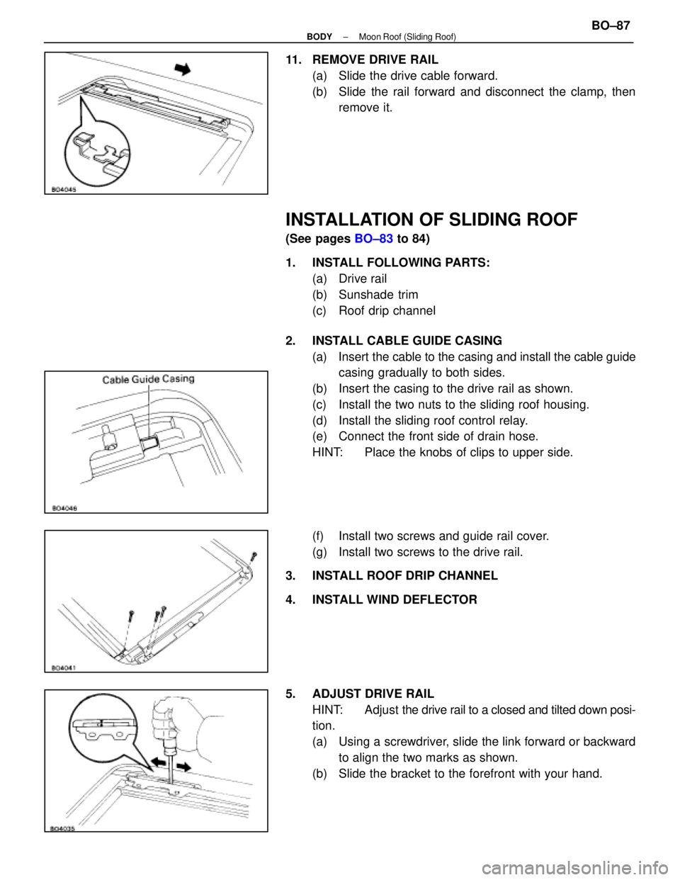
11. REMOVE DRIVE RAIL(a) Slide the drive cable forward.
(b) Slide the rail forward and disconnect the clamp, thenremove it.
INSTALLATION OF SLIDING ROOF
(See pages BO±83 to 84)
1. INSTALL FOLLOWING PARTS: (a) Drive rail
(b) Sunshade trim
(c) Roof drip channel
2. INSTALL CABLE GUIDE CASING (a) Insert the cable to the casing and install the cable guidecasing gradually to both sides.
(b) Insert the casing to the drive rail as shown.
(c) Install the two nuts to the sliding roof housing.
(d) Install the sliding roof control relay.
(e) Connect the front side of drain hose.
HINT: Place the knobs of clips to upper side.
(f) Install two screws and guide rail cover.
(g) Install two screws to the drive rail.
3. INSTALL ROOF DRIP CHANNEL
4. INSTALL WIND DEFLECTOR
5. ADJUST DRIVE RAIL HINT: Adjust the drive rail to a closed and tilted down posi-
tion.
(a) Using a screwdriver, slide the link forward or backward
to align the two marks as shown.
(b) Slide the bracket to the forefront with your hand.
±
BODY Moon Roof (Sliding Roof)BO±87
WhereEverybodyKnowsYourName
Page 445 of 4087
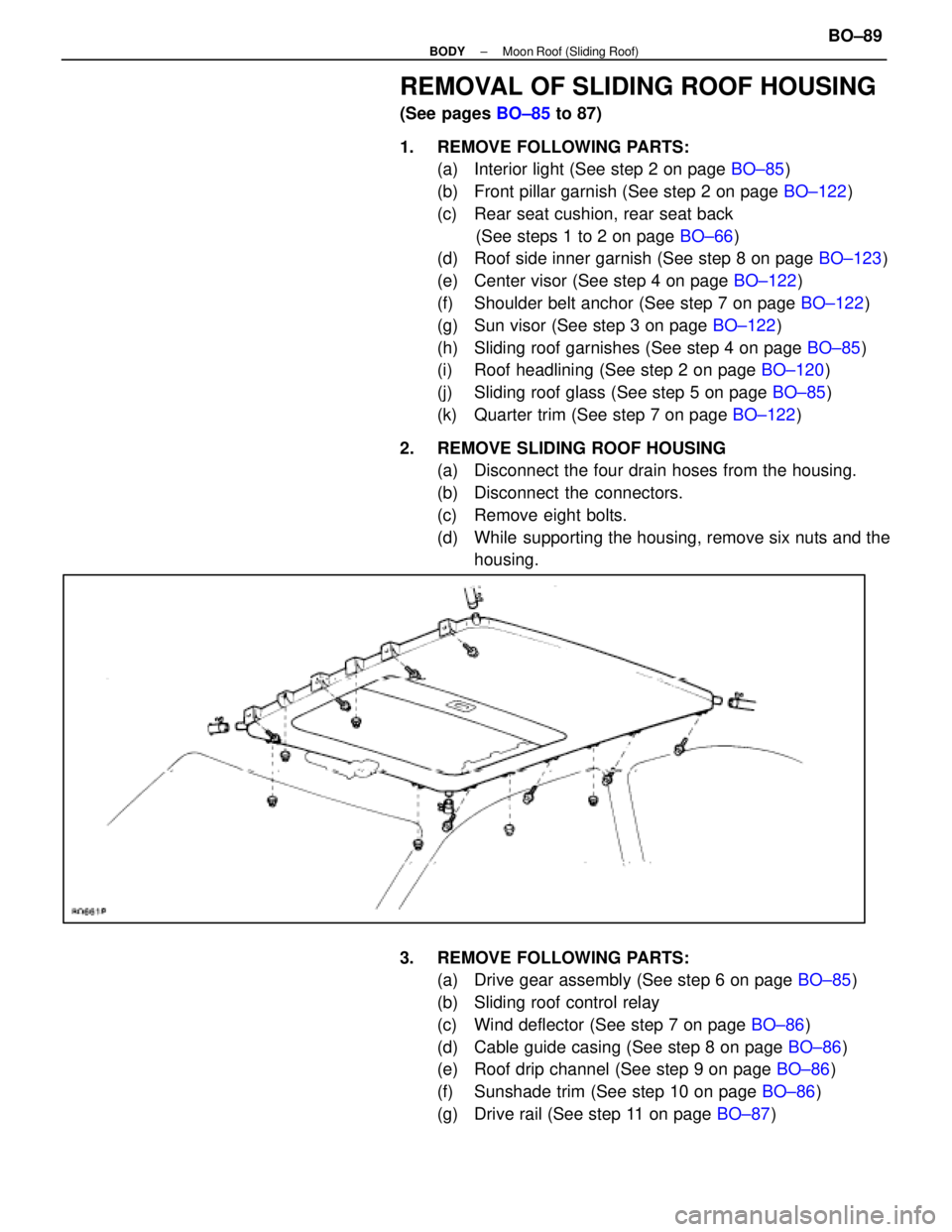
REMOVAL OF SLIDING ROOF HOUSING
(See pages BO±85 to 87)
1. REMOVE FOLLOWING PARTS: (a) Interior light (See step 2 on page BO±85)
(b) Front pillar garnish (See step 2 on page BO±122)
(c) Rear seat cushion, rear seat back (See steps 1 to 2 on page BO±66)
(d) Roof side inner garnish (See step 8 on page BO±123)
(e) Center visor (See step 4 on page BO±122)
(f) Shoulder belt anchor (See step 7 on page BO±122)
(g) Sun visor (See step 3 on page BO±122)
(h) Sliding roof garnishes (See step 4 on page BO±85)
(i) Roof headlining (See step 2 on page BO±120)
(j) Sliding roof glass (See step 5 on page BO±85)
(k) Quarter trim (See step 7 on page BO±122)
2. REMOVE SLIDING ROOF HOUSING (a) Disconnect the four drain hoses from the housing.
(b) Disconnect the connectors.
(c) Remove eight bolts.
(d) While supporting the housing, remove six nuts and thehousing.
3. REMOVE FOLLOWING PARTS: (a) Drive gear assembly (See step 6 on page BO±85)
(b) Sliding roof control relay
(c) Wind deflector (See step 7 on page BO±86)
(d) Cable guide casing (See step 8 on page BO±86)
(e) Roof drip channel (See step 9 on page BO±86)
(f) Sunshade trim (See step 10 on page BO±86)
(g) Drive rail (See step 11 on page BO±87)
±
BODY Moon Roof (Sliding Roof)BO±89
WhereEverybodyKnowsYourName
Page 539 of 4087
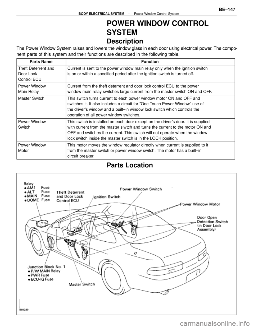
POWER WINDOW CONTROL
SYSTEM
Description
The Power Window System raises and lowers the window glass in each door usi\
ng electrical power. The compo-
nent parts of this system and their functions are described in the following\
table.
Parts NameFunction
Theft Deterrent and
Door Lock
Control ECUCurrent is sent to the power window main relay only when the ignition sw\
itch
is on or within a specified period after the ignition switch is turned o\
ff.
Power Window
Main RelayCurrent from the theft deterrent and door lock control ECU to the power
window main relay switches large current from the master switch ON and O\
FF.
Master SwitchThis switch turns current to each power window motor ON and OFF and
switches it. It also includes a circuit for ºOne Touch Power Windowº use of
the driver's window and a built±in window lock switch which controls the
operation of all power window switches.
Power Window
SwitchThis switch is installed on each door except on the driver's door. It is supplied
with current from the master siwtch and turns the current to the motor O\
N and
OFF and switches the current. This switch will not operate when the wind\
ow
lock switch inside the master switch is in the LOCK position.
Power Window
MotorThis motor moves the window regulator directly when current is supplied \
to it
from the master switch or power window switch. The motor has a built±\
in
circuit breaker.
Parts Location
±
BODY ELECTRICAL SYSTEM Power Window Control SystemBE±147
WhereEverybodyKnowsYourName
Page 544 of 4087
(Power Window Main Relay)
REMOVAL AND INSTALLATION OF
POWER WINDOW MAIN RELAY
(See page BE±16)
INSPECTION OF POWER WINDOW MAIN
RELAY
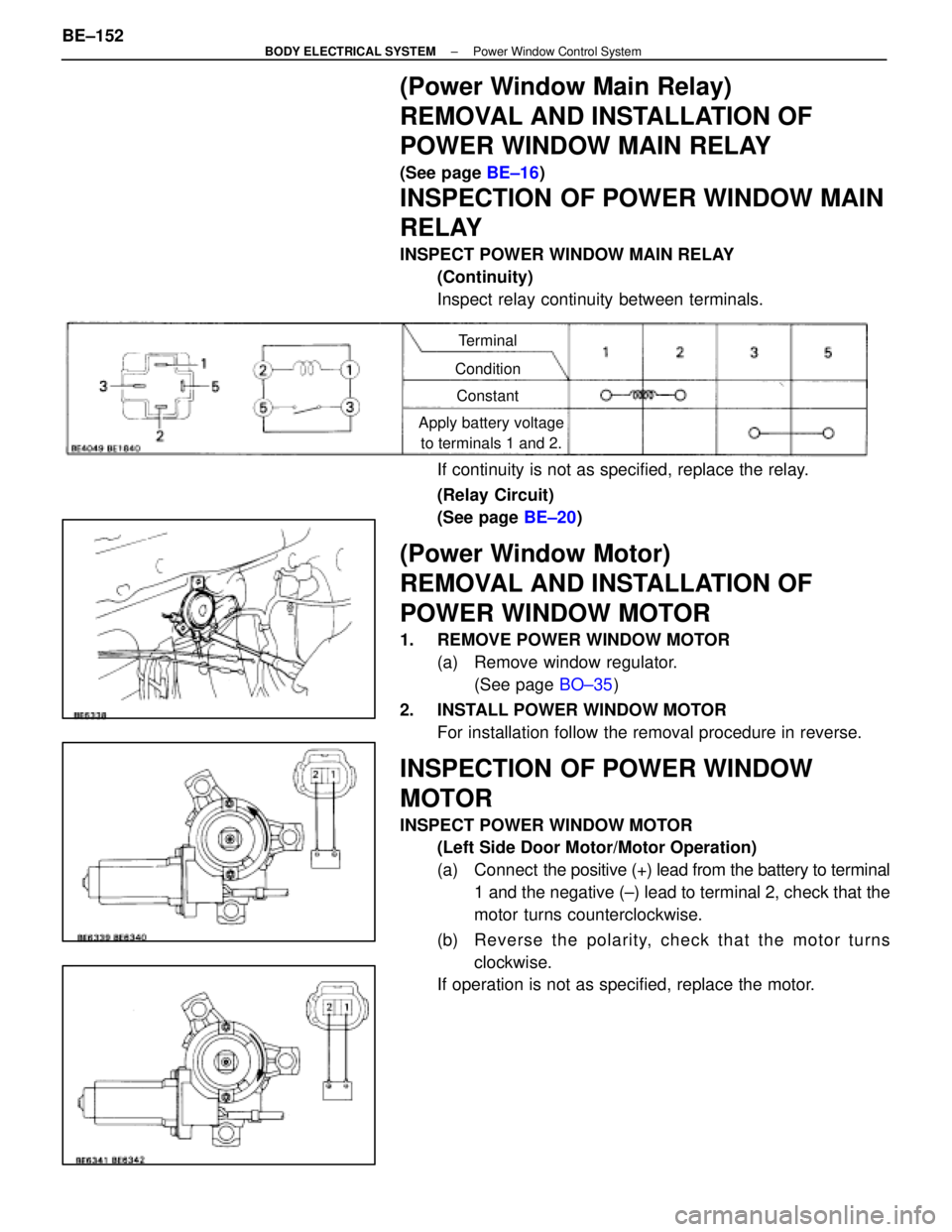
INSPECT POWER WINDOW MAIN RELAY
(Continuity)
Inspect relay continuity between terminals.
Terminal
Condition Constant
Apply battery voltage to terminals 1 and 2.
If continuity is not as specified, replace the relay.
(Relay Circuit)
(See page BE±20)
(Power Window Motor)
REMOVAL AND INSTALLATION OF
POWER WINDOW MOTOR
1. REMOVE POWER WINDOW MOTOR
(a) Remove window regulator.(See page BO±35)
2. INSTALL POWER WINDOW MOTOR For installation follow the removal procedure in reverse.
INSPECTION OF POWER WINDOW
MOTOR
INSPECT POWER WINDOW MOTOR(Left Side Door Motor/Motor Operation)
(a) Connect the positive (+) lead from the battery to terminal
1 and the negative (±) lead to terminal 2, check that the
motor turns counterclockwise.
(b) Re ve rse th e po la rity, ch e ck th a t th e mo to r tu rn s clockwise.
If operation is not as specified, replace the motor.
BE±152
±
BODY ELECTRICAL SYSTEM Power Window Control System
WhereEverybodyKnowsYourName