Page 1138 of 4087

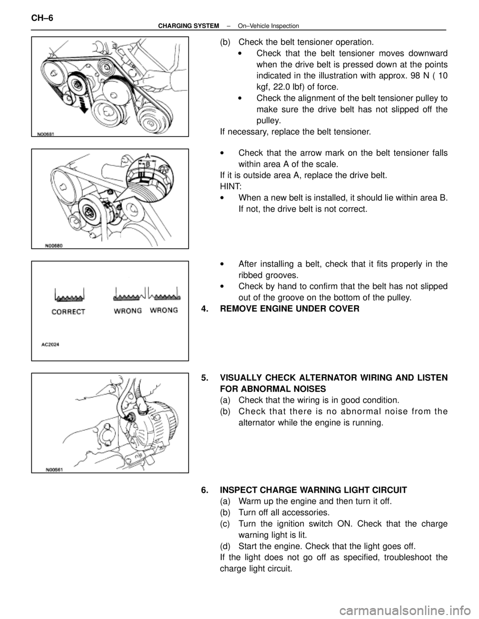
(b) Check the belt tensioner operation.w Check that the belt tensioner moves downward
when the drive belt is pressed down at the points
indicated in the illustration with approx. 98 N ( 10
kgf, 22.0 lbf) of force.
w Check the alignment of the belt tensioner pulley to
make sure the drive belt has not slipped off the
pulley.
If necessary, replace the belt tensioner.
w Check that the arrow mark on the belt tensioner falls
within area A of the scale.
If it is outside area A, replace the drive belt.
HINT:
w When a new belt is installed, it should lie within area B.
If not, the drive belt is not correct.
w After installing a belt, check that it fits properly in the
ribbed grooves.
w Check by hand to confirm that the belt has not slipped
out of the groove on the bottom of the pulley.
4. REMOVE ENGINE UNDER COVER
5. VISUALLY CHECK ALTERNATOR WIRING AND LISTEN FOR ABNORMAL NOISES
(a) Check that the wiring is in good condition.
(b) C h e c k t h a t t h e r e i s n o a bnormal noise from the
alternator while the engine is running.
6. INSPECT CHARGE WARNING LIGHT CIRCUIT (a) Warm up the engine and then turn it off.
(b) Turn off all accessories.
(c) Turn the ignition switch ON. Check that the charge
warning light is lit.
(d) Start the engine. Check that the light goes off.
If the light does not go off as specified, troubleshoot the
charge light circuit.
CH±6
±
CHARGING SYSTEM On±Vehicle Inspection
WhereEverybodyKnowsYourName
Page 1139 of 4087

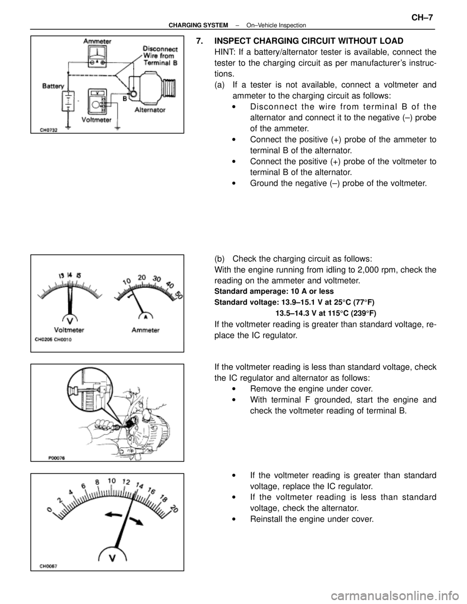
7. INSPECT CHARGING CIRCUIT WITHOUT LOADHINT: If a battery/alternator tester is available, connect the
tester to the charging circuit as per manufacturer's instruc-
tions.
(a) If a tester is not available, connect a voltmeter andammeter to the charging circuit as follows:
w Disconnect the wire from terminal B of the
alternator and connect it to the negative (±) probe
of the ammeter.
w Connect the positive (+) probe of the ammeter to
terminal B of the alternator.
w Connect the positive (+) probe of the voltmeter to
terminal B of the alternator.
w Ground the negative (±) probe of the voltmeter.
(b) Check the charging circuit as follows:
With the engine running from idling to 2,000 rpm, check the
reading on the ammeter and voltmeter.
Standard amperage: 10 A or less
Standard voltage: 13.9±15.1 V at 25 5C (77 5F)
13.5±14.3 V at 115 5C (239 5F)
If the voltmeter reading is greater than standard voltage, re-
place the IC regulator.
If the voltmeter reading is less than standard voltage, check
the IC regulator and alternator as follows:
w Remove the engine under cover.
w With terminal F grounded, start the engine and
check the voltmeter reading of terminal B.
w If the voltmeter reading is greater than standard
voltage, replace the IC regulator.
w If the voltmeter reading is less than standard
voltage, check the alternator.
w Reinstall the engine under cover.
±
CHARGING SYSTEM On±Vehicle InspectionCH±7
WhereEverybodyKnowsYourName
Page 1140 of 4087
8. INSPECT CHARGING CIRCUIT WITH LOAD(a) With the engine running at 2,000 rpm, turn on the highbeam headlights and place the heater blower switch at
ºHIº.
(b) Check the reading on the ammeter.
Standard amperage: 30 A or more
If the ammeter reading is less than standard amperage, re-
pair the alternator. (See page CH±9)
HINT: With the battery fully charged, the indication will some-
times be less than standard amperage.
9. REINSTALL ENGINE UNDER COVER
CH±8
±
CHARGING SYSTEM On±Vehicle Inspection
WhereEverybodyKnowsYourName
Page 1141 of 4087
ALTERNATOR
COMPONENTS FOR REMOVAL AND
INSTALLATION
REMOVAL OF ALTERNATOR
1. DISCONNECT CABLE FROM NEGATIVE TERMINAL OFBATTERY
CAUTION: Work must be started after approx. 20 se-
conds or longer from the time the ignition switch is
turned to the ºLOCKº position and the negative (±) termi-
nal cable is disconnected from the battery.
2. REMOVE ENGINE UNDER COVER
3. REMOVE DRIVE BELT
Loosen the belt tension by turning the drive belt tensioner
counterclockwise, and remove the drive belt.
HINT: The pulley bolt for the belt tensioner has a left±hand
thread.
±
CHARGING SYSTEM AlternatorCH±9
WhereEverybodyKnowsYourName
Page 1152 of 4087
INSTALLATION OF ALTERNATOR
(See Components on page CH±9)
1. INSTALL ALTERNATOR (a) Install the alternator and A/T oil cooler bracket with the
bolt and nut.
Torque: 37 N Vm (380 kgf Vcm, 27 ft Vlbf)
(b) Connect the alternator connector.
(c) Connect the alternator wire with the nut and cap.
2. INSTALL DRIVE BELT Install the drive belt by turning the drive belt tensioner coun-
terclockwise.
HINT: The pulley bolt for the belt tensioner has a left±hand
thread.
3. CONNECT CABLE TO NEGATIVE TERMINAL OF BATTERY
4. PERFORM ON±VEHICLE INSPECTION (See steps 6 to 8 on pages CH±6 to 8)
5. INSTALL ENGINE UNDER COVER
CH±20
±
CHARGING SYSTEM Alternator
WhereEverybodyKnowsYourName
Page 1157 of 4087
Front Door Trim Upper Panel (ABS/PVC)
Battery Insulator (PE) Roof Side Inner Garnish (ABS/PVC)
Front Pillar Garnish (ABS/PVC)
Speed Control Actuator Cover (PP)
Radiator Reserver Tank (PP)
Radiator Cover Plate (PP) Cool Air Intake
Duct (PP)
Spare Wheel Cover (PP)
Washer Jar (PP)
Junction Block Cover (PP)
Front Fender Liner (PE)
Front Fender Splash Shield (PE)
Engine Under Cover (PE) Engine Under Cover (PE)
Engine Under Cover (PP/PE)
HINT:
wResin material differs with model.
/ Made up of 2 or more kinds of materials.
PLASTIC BODY PARTSPP-5
WhereEverybodyKnowsYourName
Page 1216 of 4087
mm in.1
1.5
3.5
4
4.8
5
5.5
6 0.04
0.06
0.14
0.16
0.19
0.20
0.22
0.24
FIT STANDARDS
After doors and the engine hood are installed, be sure to perform flit a\
djustment to prevent abnormal wind
noise and ensure a good appearance.
APPENDIXAP-2
WhereEverybodyKnowsYourName
Page 1232 of 4087

mm (in.)
BO6846
BO6860
1,218
(47.95)392
(15.43)
H-U
h-u
K-o
k-O 1,186
(46.69)
H-T
h-t
393
(15.47)
D-U
D-u 379
(14.92)
G-U
g-u
1,158
(45.59)
D-T
D-t G-T
g-t
366
(14.41)
1,299
(51.14)
D-S
D-s 151
(5.94)
1,260
(49.61)
D-R
D-r
J-S
j-s187
(7.36)
1,215
(47.83)
D-Q
D-q
J-R
j-r1,192
(45.92)
1,201
(47.28)
K-q
k-Q
D-P
D-p 1,033
(40.67)
1,143
(45.0)
K-p
k-P
D-O
D-o
Vehicle Dimensions
1,689
(66.50)
847
(33.35)
205
(8.19)
1,460
(57.48) C-K, c-k
C-K, c-k
A-K, a-k
A-a
Vehicle Dimensions
*1 851 (33.50)
(Three-Dimensional Distance)
Symbol Name Hole dia. Symbol Name Hole dia.
A, a Front fender apron standard hole 10 (0.39)
L, l Front fender installation nut
6 (0.24) nut
B, b Front spring support hole-front
11 (0.43)M, m Hood hinge installation nut-rear
8 (0.31) nut
C, c Cowl side panel standard hole
10 (0.39)N, n Front fender installation nut-rear
6 (0.24) nut
D Cowl top panel center mark
O, oHead light installation nut
6 (0.24) nut
E, e Front side member working hole
18 (0.71)P, pHead light installation nut
6 (0.24) nut
F, f Front side member working hole
18 (0.71)Q, qHead light installation nut
6 (0.24) nut
G, g Radiator support standard hole
10 (0.39)R, rHead light installation nut
6 (0.24) nut
H, h Radiator support standard hole
10 (0.39)S, sHead light installation hole
11 (0.43)
I, i Front fender apron standard hole 10 (0.39)T, t Head light installation hole 10 (0.39)
J, j Front side member standard hole
8 (0.31)U, u Head light installation hole 10 (0.39)
K, k Front fender installation nut-front
6 (0.24) screw
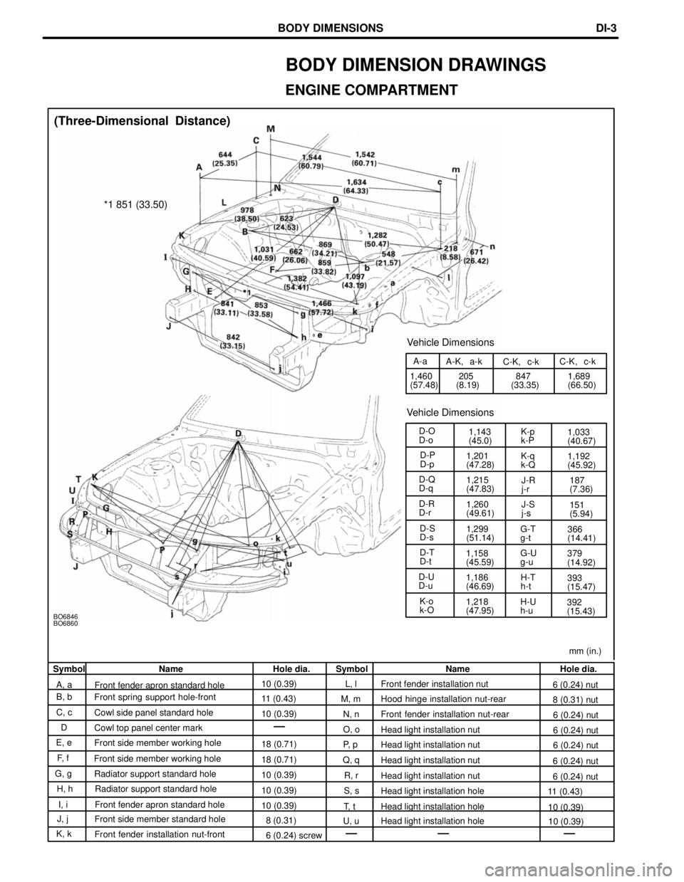
BODY DIMENSION DRAWINGS
ENGINE COMPARTMENT
BODY DIMENSIONSDI-3
WhereEverybodyKnowsYourName