Page 1119 of 4087
IN±33 ).
WIRING DIAGRAM
Ts Terminal Circuit
CIRCUIT DESCRIPTION
The sensor check circuit detects abnormalities in the speed sensor signal w\
hich can not be detected with
the diagnostic trouble code check.Connecting terminals Ts and E1 of the DLC1 in the engine compartment
starts the check.
DIAGNOSTIC CHARTDIAGNOSTIC CHART
BR±150±
BRAKE SYSTEM ANTI±LOCK BRAKE SYSTEM (ABS)
WhereEverybodyKnowsYourName
Page 1122 of 4087
TRACTION CONTROL SYSTEM (TRAC)
DESCRIPTION
BR0F3±01
The TRAC (Traction Control) system totally controls the engine torque and the braking of the driving wheels
(rear wheels). It helps avoid slippage of the driving wheels that tends to h\
appen during starting and accel-
eration and to maintain an optimal driving force according to the road surface conditions. The syst\
em elimi-
nates the need for a subtle accelerator pedal operation and improves veh\
icle stability when starting, accel-
erating or turning on slippery roads.
The TRAC system is an option.
SYSTEM PARTS LOCATION
BR0F4±01
±
BRAKE SYSTEM TRACTION CONTROL SYSTEM (TRAC)BR±153
WhereEverybodyKnowsYourName
Page 1129 of 4087

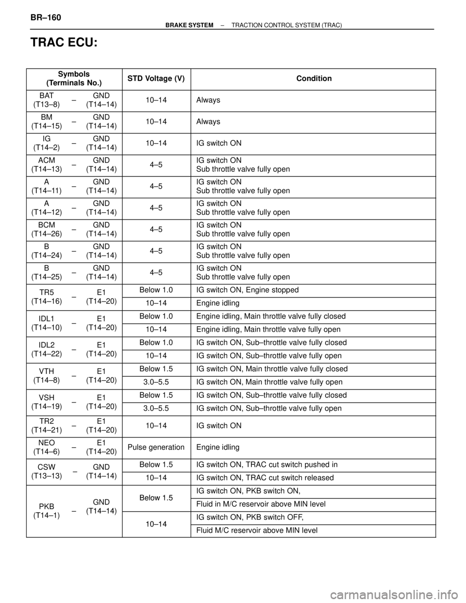
TRAC ECU:
��������� �
��������
���������Symbols
(Terminals No.)������� �
������
�������STD Voltage (V)
������������������\
���� �
������������������\
���
������������������\
����Condition
���� �
���
����BAT
(T13±8)�� ��
��
±
����� �
����
�����GND
(T14±14)������� �
������
�������10±14
������������������\
���� �
������������������\
���
������������������\
����Always
���� �
���
����
BM
(T14±15)�� ��
��±����� �
����
�����
GND
(T14±14)������� �
������
�������10±14������������������\
���� �
������������������\
���
������������������\
����Always
���� �
���
����
IG
(T14±2)�� ��
��±����� �
����
�����
GND
(T14±14)������� �
������
�������10±14������������������\
���� �
������������������\
���
������������������\
����IG switch ON
���� �
���
����
ACM
(T14±13)�� ��
��±����� �
����
�����
GND
(T14±14)������� �
������
�������
4±5������������������\
���� �
������������������\
���
������������������\
����
IG switch ON
Sub throttle valve fully open
���� ����A
(T14±11)�� ��±����� �����GND
(T14±14)������� �������4±5������������������\
���� ������������������\
����IG switch ON
Sub throttle valve fully open
���� �
���
����A
(T14±12)�� ��
��
±
����� �
����
�����GND
(T14±14)������� �
������
�������4±5
������������������\
���� �
������������������\
���
������������������\
����IG switch ON
Sub throttle valve fully open
���� �
���
����BCM
(T14±26)�� ��
��
±
����� �
����
�����GND
(T14±14)������� �
������
�������4±5
������������������\
���� �
������������������\
���
������������������\
����IG switch ON
Sub throttle valve fully open
���� �
���
����
B
(T14±24)�� ��
��
±
����� �
����
�����
GND
(T14±14)������� �
������
�������4±5
������������������\
���� �
������������������\
���
������������������\
����
IG switch ON
Sub throttle valve fully open
���� �
���
����
B
(T14±25)�� ��
��±����� �
����
�����
GND
(T14±14)������� �
������
�������4±5������������������\
���� �
������������������\
���
������������������\
����
IG switch ON
Sub throttle valve fully open
���� ����TR5�� ��±����� �����E1������� �������Below 1.0������������������\
���� ������������������\
����IG switch ON, Engine stopped
���� ����
TR5
(T14±16)�� ��±����� �����
E1
(T14±20)������� �������10±14������������������\
���� ������������������\
����Engine idling
���� ����IDL1�� ��
±
����� �����E1������� �������Below 1.0������������������\
���� ������������������\
����Engine idling, Main throttle valve fully closed
���� ����IDL1
(T14±10)�� ��±����� �����E1
(T14±20)������� �������10±14������������������\
���� ������������������\
����Engine idling, Main throttle valve fully open���� ����
IDL2
�� ��
±
����� �����
E1
������� �������Below 1.0������������������\
���� ������������������\
����IG switch ON, Sub±throttle valve fully closed���� �
���
����
IDL2
(T14±22)�� ��
��±����� �
����
�����
E1
(T14±20)������� �
������
�������10±14������������������\
���� �
������������������\
���
������������������\
����IG switch ON, Sub±throttle valve fully open
���� ����VTH�� ��±����� �����E1������� �������Below 1.5������������������\
���� ������������������\
����IG switch ON, Main throttle valve fully closed
���� ����
VTH
(T14±8)�� ��
±
����� �����
E1
(T14±20)������� �������3.0±5.5������������������\
���� ������������������\
����IG switch ON, Main throttle valve fully open
���� ����VSH�� ��±����� �����E1������� �������Below 1.5������������������\
���� ������������������\
����IG switch ON, Sub±throttle valve fully closed
���� ����
VSH
(T14±19)�� ��±����� �����
E1
(T14±20)������� �������3.0±5.5������������������\
���� ������������������\
����IG switch ON, Sub±throttle valve fully open
���� �
���
����
TR2
(T14±21)�� ��
��±����� �
����
�����
E1
(T14±20)������� �
������
�������10±14������������������\
���� �
������������������\
���
������������������\
����IG switch ON
���� �
���
����
NEO
(T14±6)�� ��
��±����� �
����
�����
E1
(T14±20)������� �
������
�������Pulse generation������������������\
���� �
������������������\
���
������������������\
����Engine idling
���� ����CSW�� ��±����� �����GND������� �������Below 1.5������������������\
���� ������������������\
����IG switch ON, TRAC cut switch pushed in
���� ����
CSW
(T13±13)�� �� ±����� �����
GND
(T14±14)������� �������10±14������������������\
���� ������������������\
����IG switch ON, TRAC cut switch released
���� ������ ������� ������������ �������
Below 1 5
������������������\
���� ������������������\
����IG switch ON, PKB switch ON,
���� ����PKB�� ��
±
����� �����GND
(T14±14)
������� �������Below 1.5������������������\
���� ������������������\
����Fluid in M/C reservoir above MIN level
���� ����PKB
(T14±1)�� ��±����� �����(T14±14)������� �������
10±14
������������������\
���� ������������������\
����IG switch ON, PKB switch OFF,���� ������ ������� ������������ �������10±14������������������\
���� ������������������\
����Fluid M/C reservoir above MIN level
BR±160±
BRAKE SYSTEM TRACTION CONTROL SYSTEM (TRAC)
WhereEverybodyKnowsYourName
Page 1133 of 4087
DESCRIPTION
The alternator is a small, high±rpm, high±performance type with an IC\
regulator incorporated. The IC regula-
tor uses integrated circuits and controls the voltage produced by the alter\
nator.
PRECAUTIONS
1. Check that the battery cables are connected to the correct terminals.
2. Disconnect the battery cables when the battery is given a quick charge.
3. Do not perform tests with a high voltage insulation resistance tester.
4. Never disconnect the battery when the engine is running. CH±2
±
CHARGING SYSTEM Description, Precautions
WhereEverybodyKnowsYourName
Page 1134 of 4087
DESCRIPTION
The alternator is a small, high±rpm, high±performance type with an\
IC regulator incorporated. The IC regula-
tor uses integrated circuits and controls the voltage produced by the alter\
nator.
PRECAUTIONS
1. Check that the battery cables are connected to the correct terminals.
2. Disconnect the battery cables when the battery is given a quick charge.
3. Do not perform tests with a high voltage insulation resistance tester.
4. Never disconnect the battery when the engine is running. CH±2
±
CHARGING SYSTEM Description, Precautions
WhereEverybodyKnowsYourName
Page 1135 of 4087
SYSTEM CIRCUIT
OPERATION
When the ignition switch is turned ON, current from the battery flows from t\
erminal L of the alternator through
the IC regulator to terminal E, causing the discharge warning light to ligh\
t up. Then when the engine is started, the voltage output increases as the alt\
ernator rpm increases. When the
voltage output becomes greater than the battery voltage, current for recharging\
flows from terminal B. Simulta-
neously, volt age at terminal L increases and the potential difference between battery and terminal L disappears,
causing the discharge warning light to go off. When the voltage output exceeds the regulator adjustment volt-
age, the transistor inside the IC regulator regulates the voltage so tha\
t the voltage from the alternator remains
constant.
±
CHARGING SYSTEM System Circuit, OperationCH±3
WhereEverybodyKnowsYourName
Page 1136 of 4087
PREPARATION
SST (SPECIAL SERVICE TOOLS)
09285±76010
Injection Pump
Camshaft Bearing
Cone ReplacerRotor rear bearing
09286±46011Injection Pump
Spline Shaft PullerRectifier end frame
09608±20012
Front Hub & Drive
Pinion Bearing Tool
Set
(09608±00030)
(Replacer)
Rotor front bearing
09820±00021Alternator Rear
Bearing Puller
09820±00030Alternator Rear
Bearing Replacer
09820±63010Alternator Pulley Set
Nut Wrench Set
RECOMMENDED TOOLS
09082±00015TOYOTA
Electrical Tester
09200±00010Engine Adjust
Kit
EQUIPMENT��������������� ���������������Part Name������������������\
���� ������������������\
����Note��������������� ���������������Battery specific gravity gauge������������������\
���� ������������������\
����Battery��������������� ���������������Vernier caliper������������������\
���� ������������������\
����Rotor (Slip ring)��������������� ���������������Torque wrench������������������\
���� ������������������\
����
CH±4±
CHARGING SYSTEM Preperation
WhereEverybodyKnowsYourName
Page 1137 of 4087

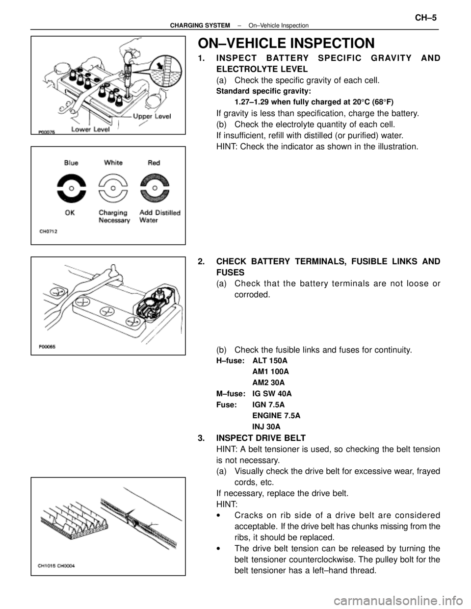
ON±VEHICLE INSPECTION
1. INSPECT BATTERY SPECIFIC GRAVITY ANDELECTROLYTE LEVEL
(a) Check the specific gravity of each cell.
Standard specific gravity:
1.27±1.29 when fully charged at 20 5C (68 5F)
If gravity is less than specification, charge the battery.
(b) Check the electrolyte quantity of each cell.
If insufficient, refill with distilled (or purified) water.
HINT: Check the indicator as shown in the illustration.
2. CHECK BATTERY TERMINALS, FUSIBLE LINKS AND FUSES
(a) Check that the battery terminals are not loose orcorroded.
(b) Check the fusible links and fuses for continuity.
H±fuse: ALT 150A AM1 100A
AM2 30A
M±fuse: IG SW 40A
Fuse: IGN 7.5A ENGINE 7.5A
INJ 30A
3. INSPECT DRIVE BELTHINT: A belt tensioner is used, so checking the belt tension
is not necessary.
(a) Visually check the drive belt for excessive wear, frayedcords, etc.
If necessary, replace the drive belt.
HINT:
w Cracks on rib side of a drive belt are considered
acceptable. If the drive belt has chunks missing from the
ribs, it should be replaced.
w The drive belt tension can be released by turning the
belt tensioner counterclockwise. The pulley bolt for the
belt tensioner has a left±hand thread.
±
CHARGING SYSTEM On±Vehicle InspectionCH±5
WhereEverybodyKnowsYourName