Page 1453 of 4087
9. REMOVE WATER INLET AND INLET HOUSING
(a) Disconnect the water bypass hose from the IAC valve.
(b) Remove the 2 bolts holding the water inlet housing to waterpump.
(c) Pull out the water inlet and inlet housing assembly.
(d) Remove the O±ring from the water inlet housing.
10. REMOVE TIMING BELT REAR PLATES
Remove the 2 bolts and rear plate. Remove the 2 rear plates.
11. REMOVE VACUUM PIPE
(a) Disconnect the following hoses: (1) California:
Vacuum hose from throttle body
(2) Except California: 3 vacuum hoses from throttle body
(3) Vacuum hose from fuel pressure regulator
(4) 2 vacuum hoses from VSV for fuel pressure control
(5) Except California:
2 vacuum hoses from EGR vacuum modulator
(6) 2 vacuum hoses (from VSV for EVAP) from vacuum pipe
(7) Vacuum hose (from VSV for fuel pressure) from air in-
take chamber
(8) Vacuum hose (from charcoal canister) from vacuum pipe
±
1UZ±FE ENGINE ENGINE MECHANICALEG±77
WhereEverybodyKnowsYourName
Page 1509 of 4087

36. INSTALL TIMING BELT REAR PLATESInstall the rear plate with the 2 bolts. Install the 2 rear plates.
Torque: 7.8 N Vm (80 kgf Vcm, 69 in. Vlbf)
37. INSTALL WATER INLET AND INLET HOUSING
(a) Remove any old packing (FIPG) material and be careful not
to drop any oil on the contact surfaces of the water inlet
housing and water pump.
wUsing a razor blade and gasket scraper, remove all the
old packing (FIPG) material from the gasket surfaces
and sealing groove.
w Thoroughly clean all components to remove all the
loose material.
w Using a non±residue solvent, clean both sealing
surfaces.
(b) Apply seal packing to the sealing groove of water inlet
housing as shown in the illustration.
Seal packing:
Part No. 08826±00100 or equivalent
wInstall a nozzle that has been cut to a 2±3 mm (0.08±0
12 in.) opening.
w Parts must be assembled within 5 minutes of
application. Otherwise the material must be removed
and reapplied.
w Immediately remove nozzle from the tube and reinstall
cap.
(c) Install a new O±ring to the water inlet housing.
(d) Apply soapy water on the O±ring.
(e) Push the water inlet housing end into the water pump hole.
(f) Install the water inlet and housing assembly with the 2 bolts. Alternately tighten the bolts.
Torque: 18 N Vm (185 kgf Vcm, 13 ft Vlbf)
HINT: Use bolts 25 mm (0.98 in.) in length.
±
1UZ±FE ENGINE ENGINE MECHANICALEG±133
WhereEverybodyKnowsYourName
Page 1529 of 4087
PREPARATION FOR DISASSEMBLY
EG34Y±01
(See Components for Cylinder Block Disassembly and As-sembly)
1. REMOVE DRIVE PLATE Remove the 8 bolts, front spacer drive plate and rear spacer.
2. INSTALL ENGINE TO ENGINE STAND FOR DISASSEMBLY
3. REMOVE TIMING BELT AND PULLEYS (See pages EG±49 to 57)
4. REMOVE CYLINDER HEAD (See pages EG±75 to 93)
5. REMOVE RH ENGINE MOUNTING BRACKET Remove the 4 bolts and mounting bracket.
6. REMOVE LH ENGINE MOUNTING BRACKET
(a) Remove the 4 bolts and mounting bracket.
(b) Remove the bolt, and disconnect the engine wire from the mounting bracket.
7. REMOVE STARTER
(a) Remove the 2 bolts, and disconnect the starter from the cylinder block.
±
1UZ±FE ENGINE ENGINE MECHANICALEG±153
WhereEverybodyKnowsYourName
Page 1565 of 4087

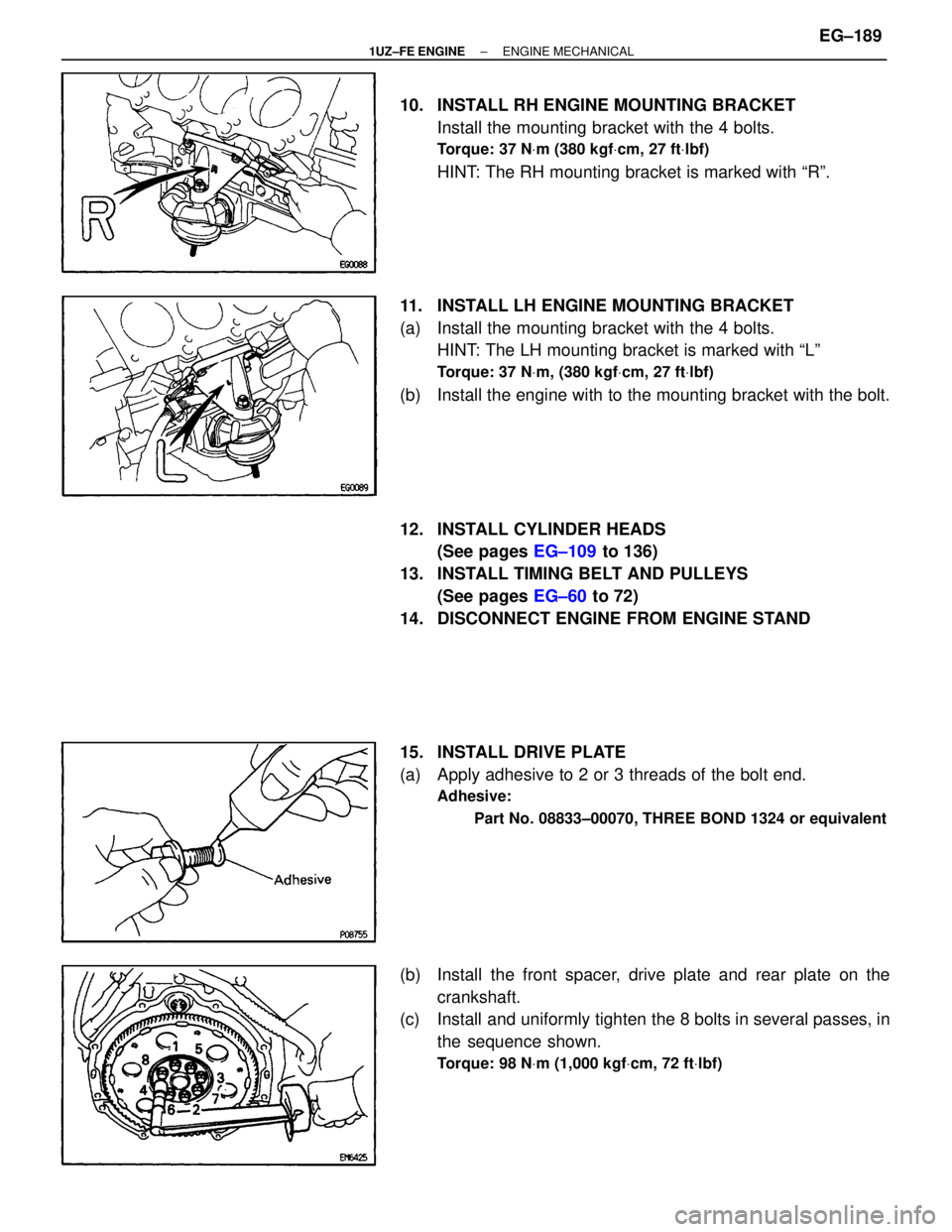
10. INSTALL RH ENGINE MOUNTING BRACKETInstall the mounting bracket with the 4 bolts.
Torque: 37 N Vm (380 kgf Vcm, 27 ft Vlbf)
HINT: The RH mounting bracket is marked with ªRº.
11. INSTALL LH ENGINE MOUNTING BRACKET
(a) Install the mounting bracket with the 4 bolts. HINT: The LH mounting bracket is marked with ªLº
Torque: 37 N Vm, (380 kgf Vcm, 27 ft Vlbf)
(b) Install the engine with to the mounting bracket with the bolt.
12. INSTALL CYLINDER HEADS
(See pages EG±109 to 136)
13. INSTALL TIMING BELT AND PULLEYS (See pages EG±60 to 72)
14. DISCONNECT ENGINE FROM ENGINE STAND
15. INSTALL DRIVE PLATE
(a) Apply adhesive to 2 or 3 threads of the bolt end.
Adhesive:
Part No. 08833±00070, THREE BOND 1324 or equivalent
(b) Install the front spacer, drive plate and rear plate on thecrankshaft.
(c) Install and uniformly tighten the 8 bolts in several passes, in
the sequence shown.
Torque: 98 N Vm (1,000 kgf Vcm, 72 ft Vlbf)
±
1UZ±FE ENGINE ENGINE MECHANICALEG±189
WhereEverybodyKnowsYourName
Page 1597 of 4087
PREPARATION FOR DISASSEMBLY
(See Components on page EM±131)
1. REMOVE DRIVE PLATE Remove the eight bolts, two spacers and drive plate.
2. INSTALL ENGINE TO ENGINE STAND FOR DISASSEMBLY
3. REMOVE TIMING BELT AND PULLEYS (See pages EM±36 to 44)
4. REMOVE Cylinder Block (See pages EM±61 to 75)
5. REMOVE RH ENGINE MOUNTING BRACKET Remove the four bolts and mounting bracket.
6. REMOVE LH ENGINE MOUNTING BRACKET (a) Remove the clamp bolt, and disconnect the engine wirefrom the engine mounting bracket.
(b) Remove the four bolts and mounting bracket.
7. REMOVE STARTER (a) Remove the two bolts, and disconnect the starter fromthe cylinder block.
EM±132
±
ENGINE MECHANICAL Cylinder Block
WhereEverybodyKnowsYourName
Page 1630 of 4087
12. INSTALL CYLINDER HEADS(See pages EM±92 to 115)
13. INSTALL TIMING PULLEYS AND BELT (See pages EM±48 to 57)
14. REMOVE ENGINE STAND FROM ENGINE
15. INSTALL DRIVE PLATE (a) Apply adhesive to two or three threads of the mountingbolt end.
Adhesive: Part No.08833±00070, THREE BOND 1324 or equiva-
lent
(b) Install the front spacer, drive plate and rear spacer on the crankshaft.
(c) Install and uniformly tighten the eight mounting bolts in
several passes in the sequence shown.
Torque: 98 N Vm (1,000 kgf Vcm, 72 ft Vlbf)
ASSEMBLY OF ENGINE AND
TRANSMISSION
(See Components on page EM±129)
1. ASSEMBLE ENGINE AND TRANSMISSION (See AT section)
2. INSTALL OIL COOLER PIPE (a) Temporarily install the two mounting bolts.
(b) Connect the two oil cooler pipes to the unions on thetransmission. Tighten the union nuts.
Torque: 34 N Vm (350 kgf Vcm, 25 ft Vlbf)
±
ENGINE MECHANICAL Cylinder BlockEM±165
WhereEverybodyKnowsYourName
Page 1642 of 4087

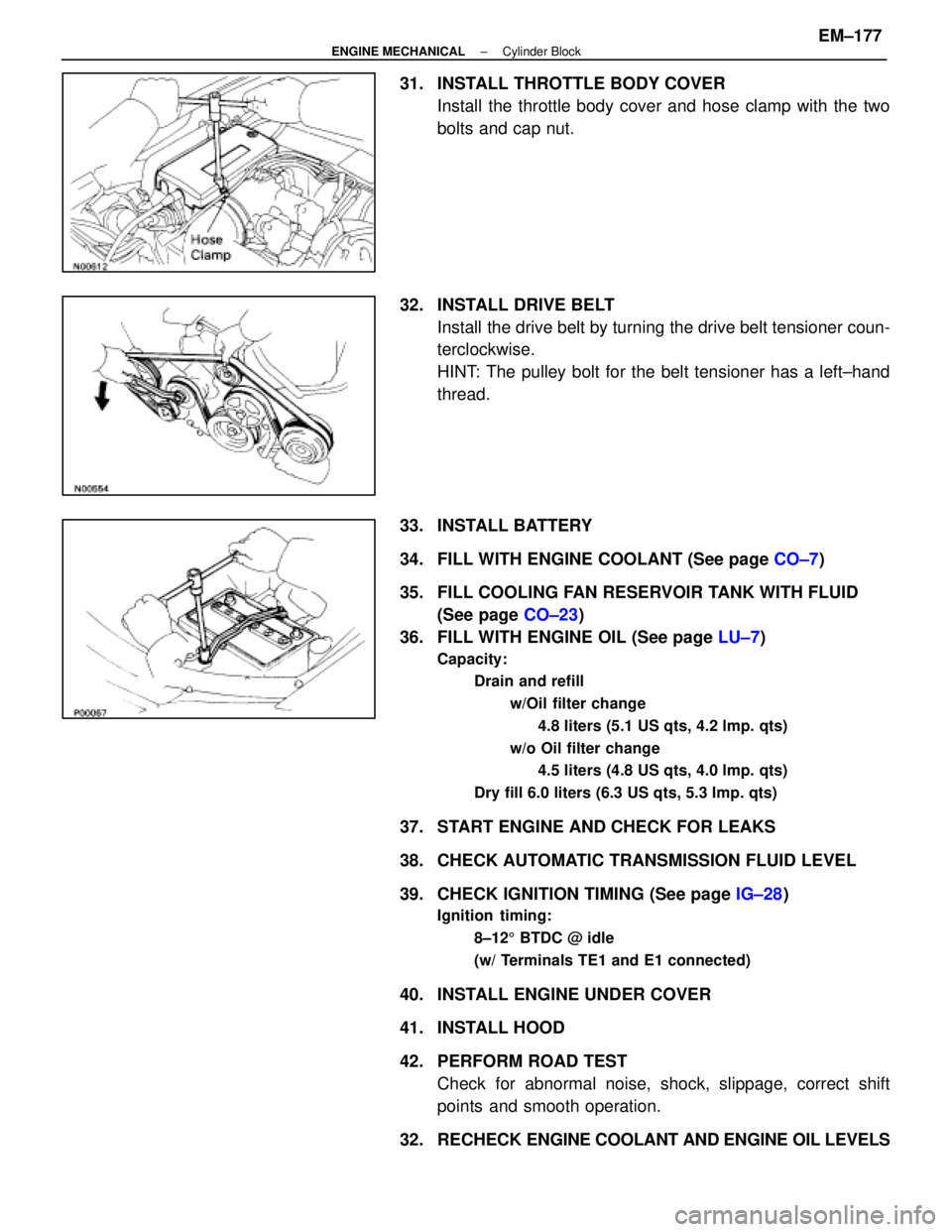
31. INSTALL THROTTLE BODY COVERInstall the throttle body cover and hose clamp with the two
bolts and cap nut.
32. INSTALL DRIVE BELT Install the drive belt by turning the drive belt tensioner coun-
terclockwise.
HINT: The pulley bolt for the belt tensioner has a left±hand
thread.
33. INSTALL BATTERY
34. FILL WITH ENGINE COOLANT (See page CO±7)
35. FILL COOLING FAN RESERVOIR TANK WITH FLUID (See page CO±23)
36. FILL WITH ENGINE OIL (See page LU±7)
Capacity:
Drain and refill
w/Oil filter change4.8 liters (5.1 US qts, 4.2 lmp. qts)
w/o Oil filter change 4.5 liters (4.8 US qts, 4.0 lmp. qts)
Dry fill 6.0 liters (6.3 US qts, 5.3 lmp. qts)
37. START ENGINE AND CHECK FOR LEAKS
38. CHECK AUTOMATIC TRANSMISSION FLUID LEVEL
39. CHECK IGNITION TIMING (See page IG±28)
Ignition timing:
8±125 BTDC @ idle
(w/ Terminals TE1 and E1 connected)
40. INSTALL ENGINE UNDER COVER
41. INSTALL HOOD
42. PERFORM ROAD TEST Check for abnormal noise, shock, slippage, correct shift
points and smooth operation.
32. RECHECK ENGINE COOLANT AND ENGINE OIL LEVELS
±
ENGINE MECHANICAL Cylinder BlockEM±177
WhereEverybodyKnowsYourName
Page 1647 of 4087

The 1 UZ±FE engine has 8±cylinders in a V±arrangement at a bank an\
gle of 905. From the front of the RH
bank cylinders are numbered 2±4±6±8, and from the front of the LH b\
ank cylinders are numbered 1 ±3±5±7.
The crankshaft is supported by 5 bearings specified by the inside of the cr\
ankcase. These bearings are made
of a copper and lead alloy. The crankshaft is integrated with 8 weights which are cast along with it\
for balancing. Oil holes are built
into the center of the crankshaft for supplying oil to the connecting ro\
ds, pistons and other components. The ignition order is 1±8±4±3±6±5±7±2. The cylinder\
head is made of aluminum alloy, with a cross flow
type intake and exhaust layout and with pent±roof type combustion chambers. The spark plugs are loca\
ted in
the center of the combustion chambers.
At the front and rear of the intake manifold, a water passage has been p\
rovided which connects the RH
and LH cylinder heads. Exhaust and intake valves are equipped with irregular pitch springs made\
of special valve spring carbon
steel which are capable of following no matter what the engine speed.
The RH and LH intake camshafts are driven by a single timing belt, and a ge\
ar on the intake camshaft en-
gages with a gear on the exhaust camshaft to drive it. The camshaft jour\
nal is supported at 5 (intake) or 4 (ex-
haust) places between the valve lifters of each cylinder and on the front end of the cylinder \
head. Lubrication
of the cam journal gear is accomplished by oil being supplied through the \
oiler port in the center of the camshaft. Adjustment of the valve clearance is done by means of an outer shim type\
system, in which valve adjusting
shims are located above the valve lifters. This permits replacement of the sh\
ims without removal of the cam-
shafts. Pistons are made of high temperature±resistant aluminum alloy, and a depression is built into the piston
head to prevent interference with valves.
Piston pins are the full±floating type, with the pins fastened to neither the piston boss nor the connecting
rods. Instead, snap rings are fitted on both ends of the pins, preventing the\
pins from falling out. The No.1 compression ring is made of steel and the No.2 compression ring\
is made of cast iron. The oil
ring is m ade of a combination of steel and stainless steel. The outer diameter of\
each piston ring is slightly larger
than the diameter of the piston and the flexibility of the rings allows them\
to hug the cylinder walls when they
are mounted on the piston. Compression rings No.1 and No.2 work to prevent \
the leakage of gas from the cylin-
der and the oil ring works to scrape oil off the cylinder walls to prevent it from entering the combustion chamber. The cylinder block is made of aluminum alloy with a bank angle of 90 5. Cast iron cylinders are installed
inside the cylinder block. It has 8 cylinders which are approximately twice the length of th\
e piston stroke. The
top of each cylinder is closed off by the cylinder heads and the lower end of the cylinders becomes the crank-
case, in which the crankshaft is installed. In addition, the cylinder bl\
ock contains a water jacket, through which
coolant is pumped to cool the cylinders. The No.1 and No.2 oil pans are bolted onto the bottom of the cylinder block\
. The No.1 oil pan is made of
aluminum alloy. The No.2 oil pan is an oil reservoir made of pressed steel sheet. An o\
il level sensor is installed
in the No.1 oil pan (If the oil level drops below a set level, a warnin\
g light lights up.). A oil pan baffle plate keeps
sufficient oil in the bottom of the No.2 oil pan even when the vehicle is tilted. \
This dividing plate also prevents
the oil from making waves when the vehicle is stopped suddenly and the oil \
shifts away from the oil pump suction
pipe. Plastic region tightening bolts are used for the cylinder head, main bearing ca\
p and connecting rod.
EM±4
±
ENGINE MECHANICAL Operation
WhereEverybodyKnowsYourName