Page 1675 of 4087
(b) Check that the timing marks of the camshaft timingpulleys and timing belt rear plates aligned.
If not, turn the crankshaft one revolution (360 5) and align the
mark as above.
20. INSPECT VALVE CLEARANCE (a) Check only those valves indicated.w Using a feeler gauge, measure the clearance
between the valve lifter and camshaft.
w Record the out±of±specification valve clearance
measurements. They will be used later to
determine the required replacement adjusting
shim.
Valve clearance (Cold):
Intake 0.15±0.25 mm (0.006±0.010 in.)
Exhaust 0.25±0.35 mm (0.010±0.014 in.)
(b) Turn the crankshaft one revolution (360 °), and align the
mark as above. (See procedure step in 19 (a))
(c) Check only the valves indicated as shown. Measure the
valve clearance.
(See procedure in step (a))
EM±16
±
ENGINE MECHANICAL Engine Tune±Up
WhereEverybodyKnowsYourName
Page 1684 of 4087

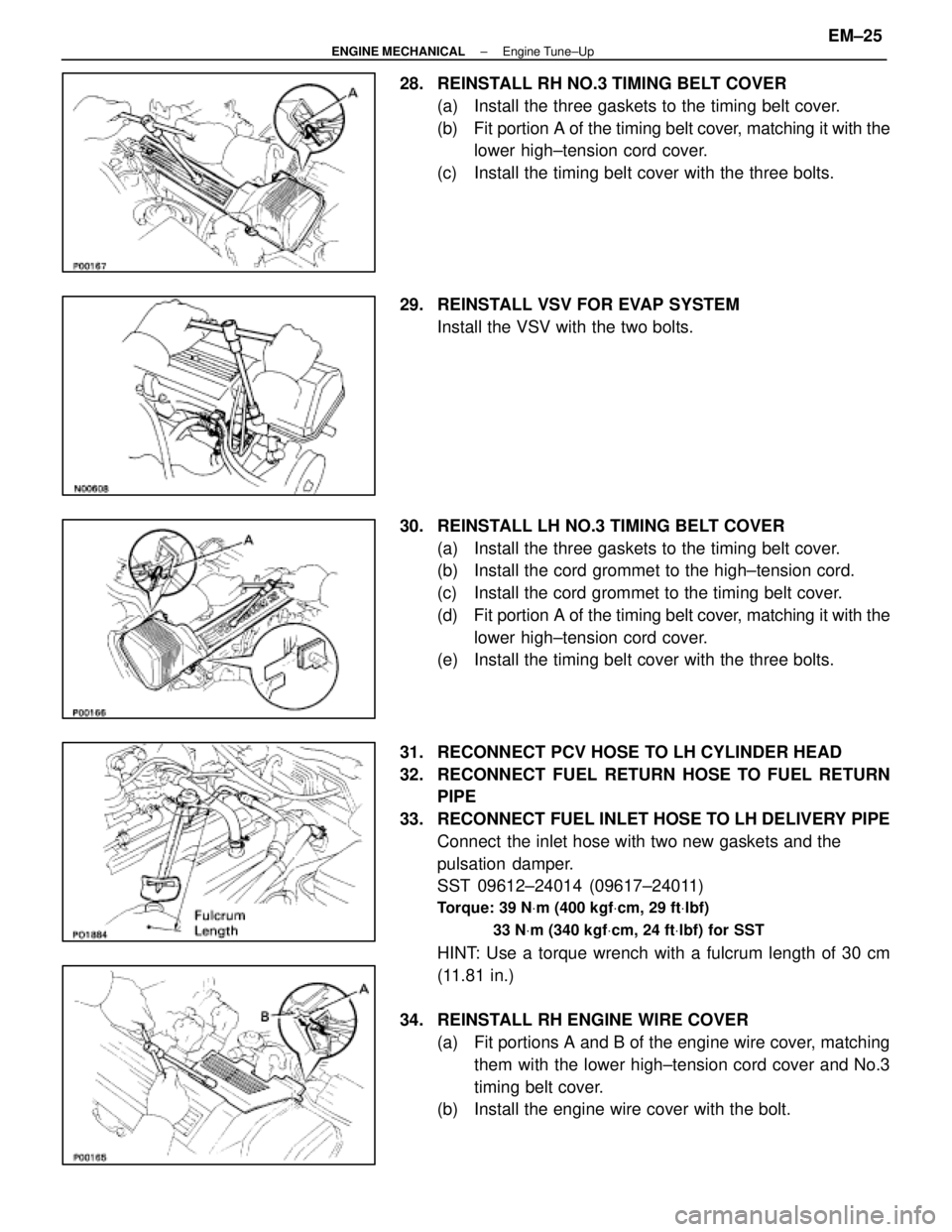
28. REINSTALL RH NO.3 TIMING BELT COVER(a) Install the three gaskets to the timing belt cover.
(b) Fit portion A of the timing belt cover, matching it with the
lower high±tension cord cover.
(c) Install the timing belt cover with the three bolts.
29. REINSTALL VSV FOR EVAP SYSTEM Install the VSV with the two bolts.
30. REINSTALL LH NO.3 TIMING BELT COVER (a) Install the three gaskets to the timing belt cover.
(b) Install the cord grommet to the high±tension cord.
(c) Install the cord grommet to the timing belt cover.
(d) Fit portion A of the timing belt cover, matching it with the
lower high±tension cord cover.
(e) Install the timing belt cover with the three bolts.
31. RECONNECT PCV HOSE TO LH CYLINDER HEAD
32. RECONNECT FUEL RETURN HOSE TO FUEL RETURN PIPE
33. RECONNECT FUEL INLET HOSE TO LH DELIVERY PIPE Connect the inlet hose with two new gaskets and the
pulsation damper.
SST 09612±24014 (09617±24011)
Torque: 39 N Vm (400 kgf Vcm, 29 ft Vlbf)
33 N Vm (340 kgf Vcm, 24 ft Vlbf) for SST
HINT: Use a torque wrench with a fulcrum length of 30 cm
(11.81 in.)
34. REINSTALL RH ENGINE WIRE COVER (a) Fit portions A and B of the engine wire cover, matchingthem with the lower high±tension cord cover and No.3
timing belt cover.
(b) Install the engine wire cover with the bolt.
±
ENGINE MECHANICAL Engine Tune±UpEM±25
WhereEverybodyKnowsYourName
Page 1685 of 4087

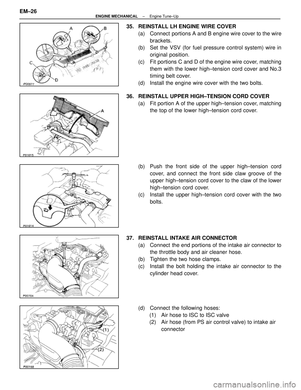
35. REINSTALL LH ENGINE WIRE COVER(a) Connect portions A and B engine wire cover to the wirebrackets.
(b) Set the VSV (for fuel pressure control system) wire in
original position.
(c) Fit portions C and D of the engine wire cover, matching them with the lower high±tension cord cover and No.3
timing belt cover.
(d) Install the engine wire cover with the two bolts.
36. REINSTALL UPPER HIGH±TENSION CORD COVER (a) Fit portion A of the upper high±tension cover, matchingthe top of the lower high±tension cord cover.
(b) Push the front side of the upper high±tension cord cover, and connect the front side claw groove of the
upper high±tension cord cover to the claw of the lower
high±tension cord cover.
(c) Install the upper high±tension cord cover with the two bolts.
37. REINSTALL INTAKE AIR CONNECTOR (a) Connect the end portions of the intake air connector tothe throttle body and air cleaner hose.
(b) Tighten the two hose clamps.
(c) Install the bolt holding the intake air connector to the cylinder head cover.
(d) Connect the following hoses: (1) Air hose to ISC to ISC valve
(2) Air hose (from PS air control valve) to intake air connector
EM±26
±
ENGINE MECHANICAL Engine Tune±Up
WhereEverybodyKnowsYourName
Page 1690 of 4087
TIMING BELT
COMPONENTS
±
ENGINE MECHANICAL Timing BeltEM±23
WhereEverybodyKnowsYourName
Page 1691 of 4087

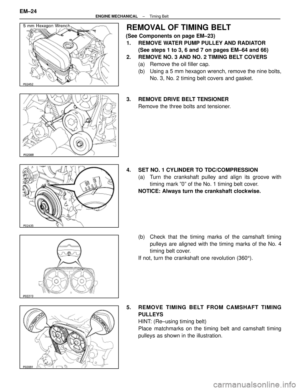
REMOVAL OF TIMING BELT
(See Components on page EM±23)1. REMOVE WATER PUMP PULLEY AND RADIATOR (See steps 1 to 3, 6 and 7 on pages EM±64 and 66)
2. REMOVE NO. 3 AND NO. 2 TIMING BELT COVERS (a) Remove the oil filler cap.
(b) Using a 5 mm hexagon wrench, remove the nine bolts,No. 3, No. 2 timing belt covers and gasket.
3. REMOVE DRIVE BELT TENSIONER Remove the three bolts and tensioner.
4. SET NO. 1 CYLINDER TO TDC/COMPRESSION (a) Turn the crankshaft pulley and align its groove withtiming mark º0º of the No. 1 timing belt cover.
NOTICE: Always turn the crankshaft clockwise.
(b) Check that the timing marks of the camshaft timing pulleys are aligned with the timing marks of the No. 4
timing belt cover.
If not, turn the crankshaft one revolution (360 5).
5. REMOVE TIMING BELT FROM CAMSHAFT TIMING PULLEYS
HINT: (Re±using timing belt)
Place matchmarks on the timing belt and camshaft timing
pulleys as shown in the illustration.
EM±24
±
ENGINE MECHANICAL Timing Belt
WhereEverybodyKnowsYourName
Page 1692 of 4087
(a) Alternately loosen the two bolts, and remove them, thetensioner and dust boot.
(b) Disconnect the timing belt from the camshaft timing pulleys.
6. REMOVE CAMSHAFT TIMING PULLEYS Using SST, remove the bolt for the timing pulley. Remove
both timing pulleys.
SST 09278±54012
7. REMOVE CRANKSHAFT PULLEY (a) Using SST to hold the crankshaft pulley, loosen thepulley mounting bolt.
SST 09213±54015 (91651±60855) and 09330±00021
(b) Remove SST and pulley bolt.
(c) Using SST, remove the pulley.
SST 09213±31021
±
ENGINE MECHANICAL Timing BeltEM±25
WhereEverybodyKnowsYourName
Page 1693 of 4087
8. REMOVE NO. 1 TIMING BELT COVERRemove the five bolts, timing belt cover and two gaskets.
9. REMOVE TIMING BELT GUIDE
10. REMOVE TIMING BELT HINT (When re±using timing belt): Draw an arrow on the tim-
ing belt in the direction of engine revolution, and place match-
marks on the timing belt and crankshaft timing pulley.
11. REMOVE IDLER PULLEY Using a 10 mm hexagon wrench, remove the pivot bolt, plate
washer and idler pulley.
12. REMOVE CRANKSHAFT TIMING PULLEY If the pulley cannot be removed by hand, use SST to remove
the crankshaft timing pulley.
SST 09213±60017 (09213±00020, 09213±00030,09213±00040, 09213±00050)
EM±26
±
ENGINE MECHANICAL Timing Belt
WhereEverybodyKnowsYourName
Page 1694 of 4087
INSPECTION OF TIMING BELT
COMPONENTS
1. INSPECT TIMING BELTNOTICE:w Do not bend, twist or turn the timing belt inside
out.
w Do not allow the timing belt to come into contact
with oil, water or steam.
w Do not make use of timing belt tension when
installing or removing the mount bolt of the
camshaft timing pulley.
If there are any defects as shown in the illustrations, check
the following points:
(a) Premature parting
w Check for proper installation.
w Check the timing cover gasket for damage and
proper installation.
(b) If the belt teeth are cracked or damaged, check to see if either the camshaft or water pump is locked.
(c) If there is noticeable wear or cracks on the belt face, check to see if there are nicks on the side of the idler
pulley lock.
(d) If there is wear or damage on only one side of the belt, check the belt guide and the alignment of each pulley.
±
ENGINE MECHANICAL Timing BeltEM±27
WhereEverybodyKnowsYourName