Page 306 of 4087

MATRIX CHART OF PROBLEM SYMPTOMS
AT0LS±08
If a normal code is displayed during the diagnostic trouble code check but\
the trouble still occurs, check
the circuits for each symptom in the order given in the charts on the fo\
llowing pages and proceed to the
page given for troubleshooting.
The Matrix Chart is divided into 3 chapters.
Chapter 1: Electronic Circuit Matrix Chart
Chapter 2: On±vehicle Repair Matrix Chart
Chapter 3: Off±vehicle Repair Matrix Chart
In troubleshooting, check Chapter 1 first. If instructions are given in Ch\
apter 1 to proceed to Chapter 2 or
3, proceed to it.
1. If the instruction ªProceed to next circuit inspection shown on matrix chartº is given in the flow chart for each circuit, proceed to the circuit with the next highest number in the\
table to continue
the check.
2. If the trouble still occurs even though there are no abnormalities in an\
y of the other circuits, then check or replace the ECM.
±
A304E (1UZ±FE) AUTOMATIC TRANSMISSION TROUBLESHOOTINGAT±65
WhereEverybodyKnowsYourName
Page 321 of 4087

OKNG
OKNG
INSPECTION PROCEDURE
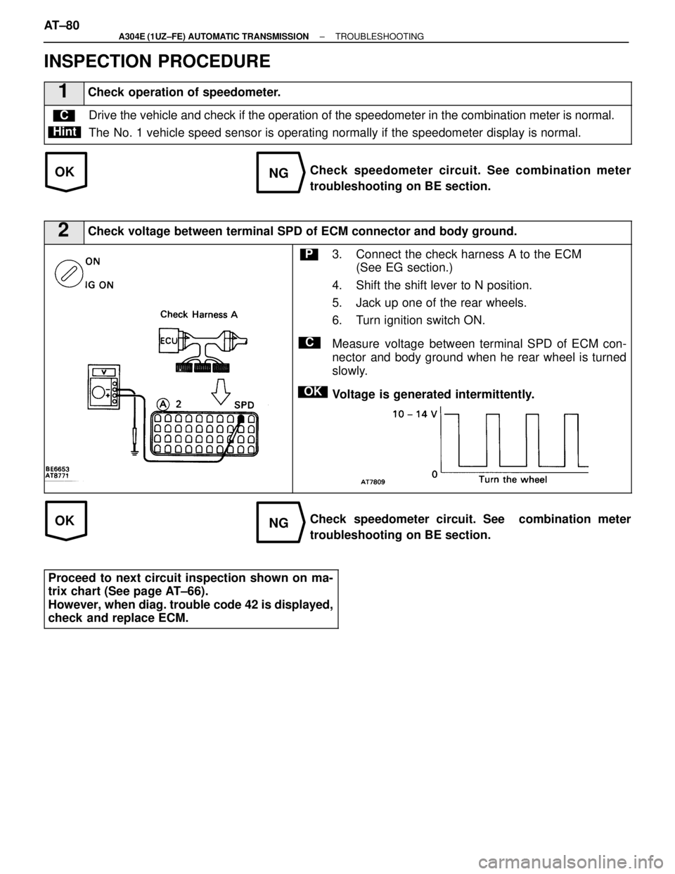
1Check operation of speedometer.
Drive the vehicle and check if the operation of the speedometer in the c\
ombination meter is normal.
The No. 1 vehicle speed sensor is operating normally if the speedometer dis\
play is normal.C
Hint
Check speedometer circuit. See combination meter
troubleshooting on BE section.
2Check voltage between terminal SPD of ECM connector and body ground.
C
OK
P3. Connect the check harness A to the ECM (See EG section.)
4. Shift the shift lever to N position.
5. Jack up one of the rear wheels.
6. Turn ignition switch ON.
Measure voltage between terminal SPD of ECM con-
nector and body ground when he rear wheel is turned
slowly.
Voltage is generated intermittently.
Check speedometer circuit. See combination meter
troubleshooting on BE section.
Proceed to next circuit inspection shown on ma-
trix chart (See page AT±66).
However, when diag. trouble code 42 is displayed,
check and replace ECM.
AT±80±
A304E (1UZ±FE) AUTOMATIC TRANSMISSION TROUBLESHOOTING
WhereEverybodyKnowsYourName
Page 325 of 4087
OKNG
2Check harness and connector between battery and No. 4 solenoid valve, No. 4 solenoid valve\
and ECM (See page IN±33).
Repair or replace harness or connector.
Proceed to next circuit inspection shown on ma-
trix chart (See page AT±66). However, when diag.
trouble code 46 is display, check and replace ECM.
±
A304E (1UZ±FE) AUTOMATIC TRANSMISSION TROUBLESHOOTINGAT±85
WhereEverybodyKnowsYourName
Page 332 of 4087

OKNG
OKNG
INSPECTION PROCEDURE
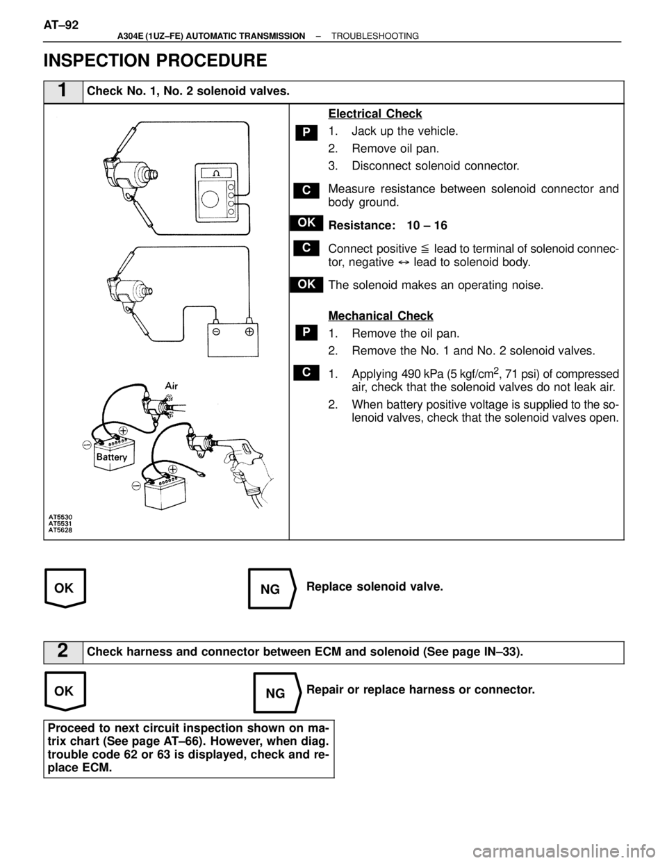
1Check No. 1, No. 2 solenoid valves.
C
OK
P
C
P
OK
C
Electrical Check
1. Jack up the vehicle.
2. Remove oil pan.
3. Disconnect solenoid connector.
Measure resistance between solenoid connector and
body ground.
Resistance: 10 ± 16 �
Connect positive � lead to terminal of solenoid connec-
tor, negative � lead to solenoid body.
The solenoid makes an operating noise.
Mechanical Check
1. Remove the oil pan.
2. Remove the No. 1 and No. 2 solenoid valves.
1. Applying 490 kPa (5 kgf/cm
2, 71 psi) of compressed
air, check that the solenoid valves do not leak air.
2. When battery positive voltage is supplied to the so-
lenoid valves, check that the solenoid valves open.
Replace solenoid valve.
2Check harness and connector between ECM and solenoid (See page IN±33\
).
Repair or replace harness or connector.
Proceed to next circuit inspection shown on ma-
trix chart (See page AT±66). However, when diag.
trouble code 62 or 63 is displayed, check and re-
place ECM.
AT±92±
A304E (1UZ±FE) AUTOMATIC TRANSMISSION TROUBLESHOOTING
WhereEverybodyKnowsYourName
Page 337 of 4087
OKNG
2Check harness and connector between battery and No. 4 solenoid valve, No. 4 solenoid valve\
and ECM (See page IN±33).
Repair or replace harness or connector.
Proceed to next circuit inspection shown on ma-
trix chart (See page AT±66). However, when diag.
trouble code 64 is display, check and replace ECM.
±
A304E (1UZ±FE) AUTOMATIC TRANSMISSION TROUBLESHOOTINGAT±97
WhereEverybodyKnowsYourName
Page 340 of 4087

NGNG
OKNG
INSPECTION PROCEDURE
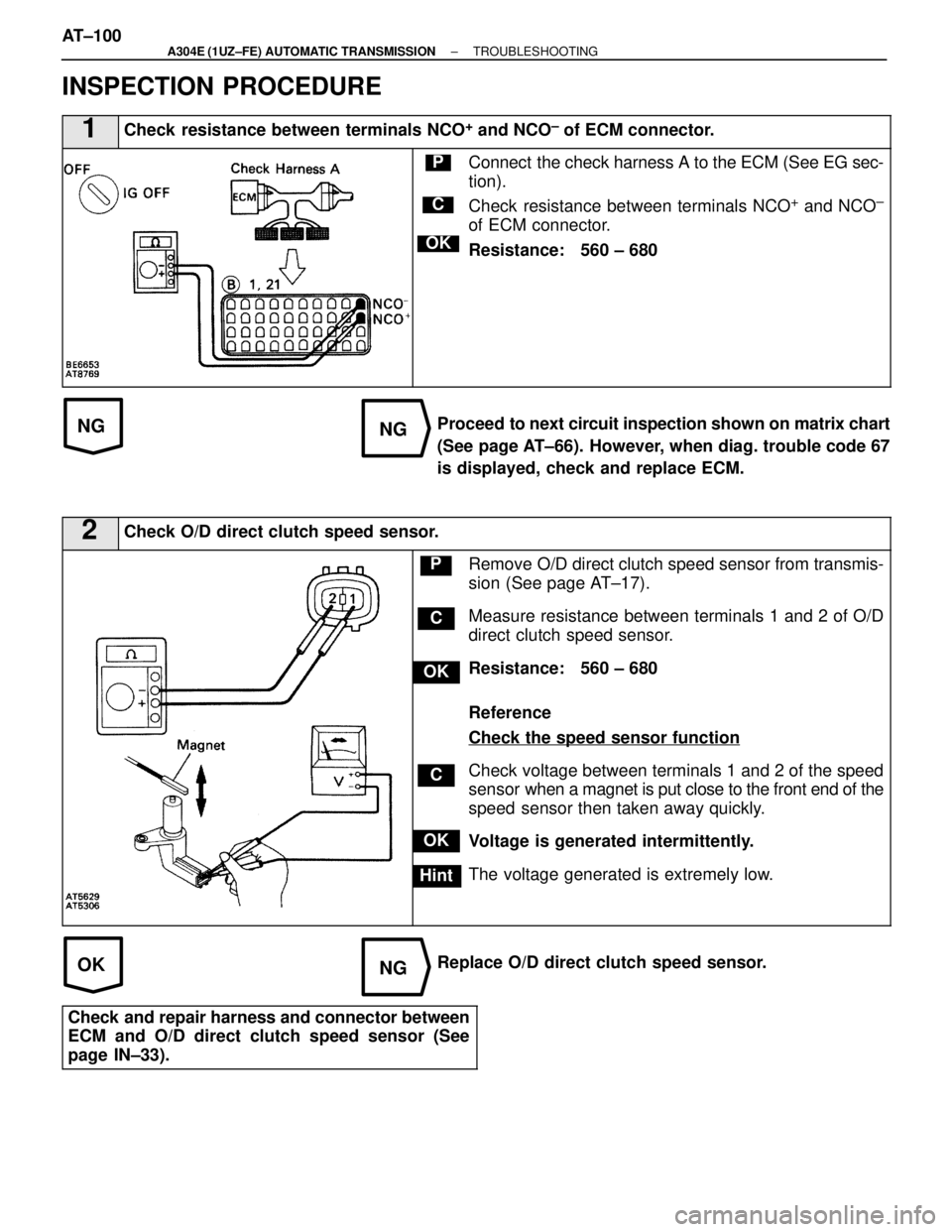
1Check resistance between terminals NCO+ and NCO± of ECM connector.
C
OK
PConnect the check harness A to the ECM (See EG sec-
tion).
Check resistance between terminals NCO
+ and NCO±
of ECM connector.
Resistance: 560 ± 680 �
Proceed to next circuit inspection shown on matrix chart
(See page AT±66). However, when diag. trouble code 67
is displayed, check and replace ECM.
2Check O/D direct clutch speed sensor.
C
OK
Hint
P
OK
C
Remove O/D direct clutch speed sensor from transmis-
sion (See page AT±17).
Measure resistance between terminals 1 and 2 of O/D
direct clutch speed sensor.
Resistance: 560 ± 680 �
Reference
Check the speed sensor function
Check voltage between terminals 1 and 2 of the speed
sensor when a magnet is put close to the front end of the
speed sensor then taken away quickly.
Voltage is generated intermittently.
The voltage generated is extremely low.
Replace O/D direct clutch speed sensor.
Check and repair harness and connector between
ECM and O/D direct clutch speed sensor (See
page IN±33).
AT±100±
A304E (1UZ±FE) AUTOMATIC TRANSMISSION TROUBLESHOOTING
WhereEverybodyKnowsYourName
Page 352 of 4087
WIRING DIAGRAM
O/D Main Switch and O/D OFF Indicator Light Circuit
CIRCUIT DESCRIPTION
The O/D main switch contacts go off when the switch is pushed in and comes on when it is pushed out.
In O/D main switch OFF position, the O/D OFF indicator lights up, and the \
ECM prohibits shifting to over-
drive. The ECM also causes the O/D OFF indicator light to blink when a malfunc\
tion is detected. In this
case, connecting the terminals in the DLC2 or DLC1 can display the malfu\
nction code.
DIAGNOSTIC CHARTDIAGNOSTIC CHART
See next page.
AT±112
±
A304E (1UZ±FE) AUTOMATIC TRANSMISSION TROUBLESHOOTING
WhereEverybodyKnowsYourName
Page 358 of 4087
AT±66
IN±33
WIRING DIAGRAM
TE1 Terminal Circuit
CIRCUIT DESCRIPTION
ECM displays diagnostic trouble codes using the O/D OFF indicator light \
when terminals TE and E of the
DLC2 or DLC1 are connected.
DIAGNOSTIC CHARTDIAGNOSTIC CHART
AT±118±
A304E (1UZ±FE) AUTOMATIC TRANSMISSION TROUBLESHOOTING
WhereEverybodyKnowsYourName