Page 1511 of 4087

(b) Connect the vacuum hose to the air intake chamber.
42. INSTALL TWC (FRONT)
(a) Using a 14 deep socket wrench, install a new gasket and theTWC with 3 new nuts. Install the 2 TWC.
Torque: 62 N Vm (630 kgf Vcm, 46 ft Vlbf)
(b) Te m p o r a r i l y i n s t a l l t h e p i p e s upport bracket to the
transmission with the 4 bolts.
(c) Install a new gasket to each front end of the front exhaust
pipe.
(d) Connect the front exhaust pipe to the 2 TWC with the 4 bolts and 4 new nuts.
Torque: 43 N Vm (440 kgf Vcm, 32 ft Vlbf)
(e) Tighten the 4 bolts holding the pipe support bracket to the
transmission.
Torque: 43 N Vm (440 kgf Vcm, 32 ft Vlbf)
43. INSTALL HYDRAULIC PUMP
Install the hydraulic pump with the 2 bolts and 2 nuts.
Torque:
16 NVm (160 kgf Vcm, 12 ft Vlbf) for 12 mm head
30 N Vm (310 kgf Vcm, 22 ft Vlbf) for 14 mm head
HINT: Each bolt length is indicated in the illustration.
Bolt length:
106 mm (4.17 in.) for A of 12 mm head
114 mm (4.49 in.) for B of 14 mm head
44. INSTALL RH CAMSHAFT TIMING PULLEY
(a) Align the camshaft knock pin with the knock pin groove of the
timing pulley, and slide on the timing pulley.
(b) Slide the timing pulley on the camshaft, facing the ªRº mark forward.
(c) Using SST, install the pulley bolt. SST 09278±54012
Torque: 108 N Vm (1,100 kgf Vcm, 80 ft Vlbf)
±
1UZ±FE ENGINE ENGINE MECHANICALEG±135
WhereEverybodyKnowsYourName
Page 1516 of 4087

7. REMOVE THROTTLE BODY COVER
(a) Disconnect the EVAP hose from the hose clamp.
(b) Remove the cap nut.
(c) Loosen the 2 bolts, and remove the hose clamp and throttlebody cover.
8. DISCONNECT CONTROL CABLES TO THROTTLE BODY Disconnect the following cables:
(1) Accelerator cable
(2) Transmission throttle control cable
(3) Cruise control actuator cable
9. REMOVE AIR CLEANER
(a) Disconnect the VAF meter connector.
(b) Remove the hose clamp bolt holding the air cleaner hose to the intake air connector.
(c) Remove the 4 bolts.
(d) Disconnect the air cleaner hose from the intake air connector.
(e) Disconnect the air duct from the air cleaner case, and remove
the air cleaner.
10. D I S C O N N E C T VA CUUM HOSE (A) (FROM PS AIR
CONTROL VALVE) FROM AIR INTAKE CHAMBER
11. REMOVE INTAKE AIR CONNECTOR
(a) Disconnect the following hoses from the intake air connector:
(1) Air hose (from IAC valve)
(2) Air hose (from air control valve on PS pump)
(b) Remove the hose clamp bolt holding the intake air connector to the throttle body.
(c) Remove the bolt and intake air connector.
EG±140
±
1UZ±FE ENGINE ENGINE MECHANICAL
WhereEverybodyKnowsYourName
Page 1520 of 4087

22. DISCONNECT POWER STEERING (PS) RESERVOIRTANK AND BRACKET FROM BODY
Remove the 3 bolts, and disconnect the reservoir tank and
bracket assembly.
23. DISCONNECT POWER STEERING (PS) PUMP FROM ENGINE
Remove the nut and 3 bolts, and disconnect the PS pump
from the engine.
HINT: Put aside the PS pump, and suspend it.
24. DISCONNECT AIR CONDITIONING (A/C) COMPRESSOR FROM ENGINE
(a) Disconnect the A/C compressor connector.
(b) Remove the nut, and disconnect the ground cable from the
A/C compressor stay.
(c) Remove the bolt and A/C compressor stay.
(d) Remove the 2 bolts, and disconnect the A/C compressor from the engine.
HINT: Put aside the A/C compressor, and suspend it.
25. DISCONNECT HOSES Disconnect the following hoses and ground strap:
(1) Heater water hose from water bypass hose
(2) Heater water hose from heater water valve
(3) Brake booster hose from union on air intake chamber
(4) Vacuum hose (from VSV for heater water valve) from air
intake chamber
(5) Ground strap from bracket on body.
EG±144
±
1UZ±FE ENGINE ENGINE MECHANICAL
WhereEverybodyKnowsYourName
Page 1573 of 4087
12. INSTALL CHARCOAL CANISTER
(a) Install the charcoal canister.
(b) Connect the vacuum hose and air hose to the charcoalcanister.
13. CONNECT HOSES Connect the following hoses and ground strap:
(1) Heater water hose to water bypass hose
(2) Heater water hose to heater water valve
(3) Brake booster hose to union on air intake chamber
(4) Vacuum hose (from VSV for heater water valve) to air in-
take chamber
(5) Ground strap to bracket on body
(6) Fuel inlet hose to fuel tube
SST 09278±54012
Torque: 30 N Vm (310 kgf Vcm, 22 ft Vlbf)
HINT: Use a torque wrench with a fulcrum length of 30 cm
(11.81 in.).
(7) Fuel return hose to return pipe
14. INSTALL AIR CONDITIONING (A/C) COMPRESSOR
(a) Install the A/C compressor, compressor stay and ground cable with the nut and 3 bolts.
Torque:
49 NVm (500 kgf Vcm, 36 ft Vlbf) for bolt
29 N Vm (300 kgf Vcm, 22 ft Vlbf) for nut
(b) Connect the A/C compressor connector.
±
1UZ±FE ENGINE ENGINE MECHANICALEG±197
WhereEverybodyKnowsYourName
Page 1577 of 4087
(f) Connect the ECT sensor connector (for cooling fan).
(g) Install the ECT sensor wire clamp to the radiator fan shroud.
26. INSTALL RADIATOR RESERVOIR TANK
(a) Install the reservoir tank to the reservoir tank bracket.
(b) Install the reservoir tank with the bracket and 3 bolts.
Torque: 4.9 N.m (50 kgfVcm, 43 in. Vlbf)
(c) Connect the following hoses:
(1) Reservoir hose to water inlet housing
(2) Reservoir hose to radiator
(d) Connect the coolant level sensor connector.
27. INSTALL INTAKE AIR CONNECTOR
(a) Connect the intake air connector to the throttle body.
(b) Install the hose clamp and bolt.
(c) Connect the following hoses to the intake air connector: (1) Air hose (from IAC valve)
(2) Air hose (from air control valve on PS pump)
28. CONNECT VACUUM HOSE (A) (FROM PS AIR CONTROL VALVE) TO AIR INTAKE CHAMBER
±
1UZ±FE ENGINE ENGINE MECHANICALEG±201
WhereEverybodyKnowsYourName
Page 1578 of 4087
29. INSTALL AIR CLEANER
(a) Connect the air cleaner case to the air duct.
(b) Connect the air cleaner hose to the intake air connector.
(c) Install the air cleaner with the 3 bolts.
(d) Tighten the hose clamp bolt holding the air cleaner hose tothe intake air connector.
(e) Connect the VAF meter connector.
30. CONNECT CONTROL CABLES TO THROTTLE BODY
Connect the following cables:
(1) Accelerator cable
(2) Transmission throttle control cable
(3) Cruise control actuator cable
31. INSTALL THROTTLE BODY COVER
(a) Install the thro ttle body cover and hose clamp with the cap nut
and 2 bolts.
(b) Install the EVAP hose to the hose clamp.
32. INSTALL DRIVE BELT Install the drive belt by turning the drive belt tensioner coun-
terclockwise.
HINT: The pulley bolt for the dive belt tensioner has a left±
hand thread.
33. INSTALL BATTERY
EG±202
±
1UZ±FE ENGINE ENGINE MECHANICAL
WhereEverybodyKnowsYourName
Page 1584 of 4087

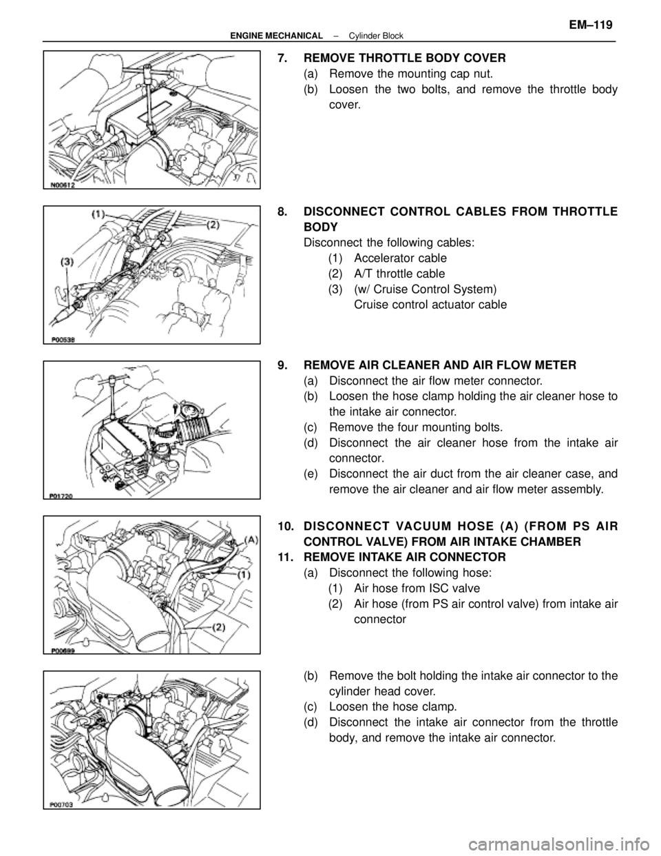
7. REMOVE THROTTLE BODY COVER(a) Remove the mounting cap nut.
(b) Loosen the two bolts, and remove the throttle bodycover.
8. DISCONNECT CONTROL CABLES FROM THROTTLE BODY
Disconnect the following cables:(1) Accelerator cable
(2) A/T throttle cable
(3) (w/ Cruise Control System) Cruise control actuator cable
9. REMOVE AIR CLEANER AND AIR FLOW METER (a) Disconnect the air flow meter connector.
(b) Loosen the hose clamp holding the air cleaner hose tothe intake air connector.
(c) Remove the four mounting bolts.
(d) Disconnect the air cleaner hose from the intake air connector.
(e) Disconnect the air duct from the air cleaner case, and remove the air cleaner and air flow meter assembly.
10. D I S C O N N E C T VA CUUM HOSE (A) (FROM PS AIR
CONTROL VALVE) FROM AIR INTAKE CHAMBER
11. REMOVE INTAKE AIR CONNECTOR
(a) Disconnect the following hose:(1) Air hose from ISC valve
(2) Air hose (from PS air control valve) from intake air connector
(b) Remove the bolt holding the intake air connector to the cylinder head cover.
(c) Loosen the hose clamp.
(d) Disconnect the intake air connector from the throttle
body, and remove the intake air connector.
±
ENGINE MECHANICAL Cylinder BlockEM±119
WhereEverybodyKnowsYourName
Page 1588 of 4087

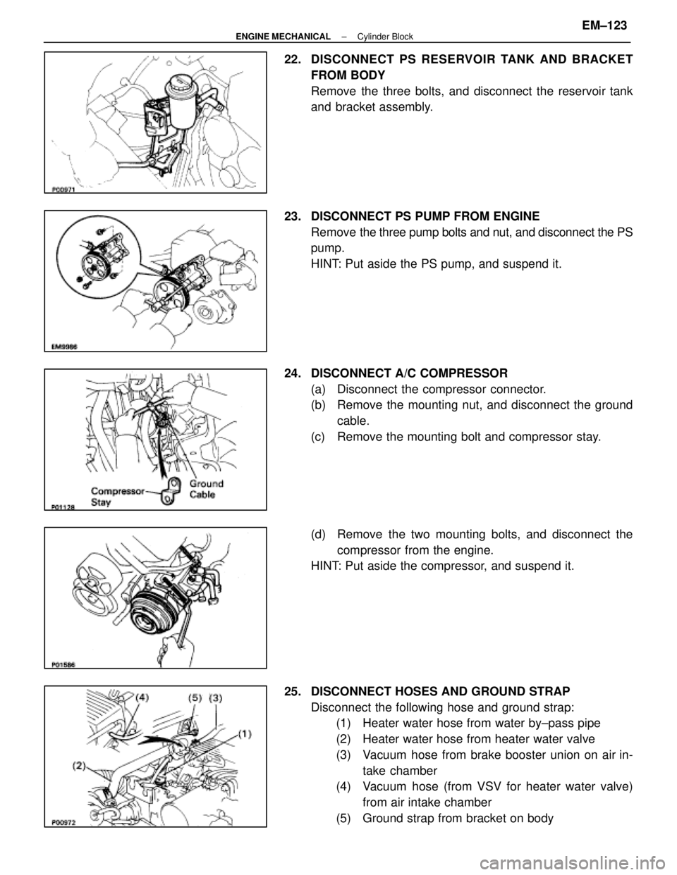
22. DISCONNECT PS RESERVOIR TANK AND BRACKET
FROM BODY
Remove the three bolts, and disconnect the reservoir tank
and bracket assembly.
23. DISCONNECT PS PUMP FROM ENGINE Remove the three pump bolts and nut, and disconnect the PS
pump.
HINT: Put aside the PS pump, and suspend it.
24. DISCONNECT A/C COMPRESSOR (a) Disconnect the compressor connector.
(b) Remove the mounting nut, and disconnect the groundcable.
(c) Remove the mounting bolt and compressor stay.
(d) Remove the two mounting bolts, and disconnect the compressor from the engine.
HINT: Put aside the compressor, and suspend it.
25. DISCONNECT HOSES AND GROUND STRAP Disconnect the following hose and ground strap:(1) Heater water hose from water by±pass pipe
(2) Heater water hose from heater water valve
(3) Vacuum hose from brake booster union on air in-
take chamber
(4) Vacuum hose (from VSV for heater water valve)
from air intake chamber
(5) Ground strap from bracket on body
±
ENGINE MECHANICAL Cylinder BlockEM±123
WhereEverybodyKnowsYourName