Page 1636 of 4087
(g) Install the scuff plate.
(h) Connect the connectors.
(i) Install the lower instrument panel finish panel and glovecompartment door assembly with the four screws.
(j) Install the instrument panel under cover with the two clips.
12. INSTALL CHARCOAL CANISTER (a) Install the charcoal canister.
(b) Connect the vacuum hose and air hose to the charcoalcanister.
13. CONNECT HOSES Connect the following hose and ground strap:(1) Heater water hose to water by±pass pipe
(2) Heater water hose to heater water valve
(3) Vacuum hose to brake booster union on air intake
chamber
(4) Vacuum hose (from VSV for heater water valve) to
air intake chamber
(5) Ground strap to bracket on body
±
ENGINE MECHANICAL Cylinder BlockEM±171
WhereEverybodyKnowsYourName
Page 1641 of 4087
 Connect the following hoses:(1) Reservoir hose to water inlet housing
(2) Reservoir hose to radiator
(d) Connect the coolant level sensor connector.
27. INSTALL INTAKE AIR CONNECTOR (a) Con")
(c) Connect the following hoses:(1) Reservoir hose to water inlet housing
(2) Reservoir hose to radiator
(d) Connect the coolant level sensor connector.
27. INSTALL INTAKE AIR CONNECTOR (a) Connect the intake air connector to the throttle body.
(b) Install the hose clamp and mounting bolt.
(c) Connect the following hoses:(1) Air hose to ISC valve
(2) Air hose (from PS air control valve) to air intake chamber
28. CONNECT VACUUM HOSE (A) (FROM PS AIR CONTROL VALVE) TO AIR INTAKE CHAMBER
29. INSTALL AIR CLEANER AND AIR FLOW METER (a) Connect the air cleaner case to the air duct.
(b) Connect the air cleaner hose to the intake air connector.
(c) Install the four mounting bolts and hose clamp.
(d) Connect the air flow meter connector.
30. CONNECT CONTROL CABLES TO THROTTLE BODY Connect the following cables:(1) Accelerator cable
(2) A/T throttle cable
(3) (w/ Cruise Control System)
Cruise control actuator cable
EM±176
±
ENGINE MECHANICAL Cylinder Block
WhereEverybodyKnowsYourName
Page 1658 of 4087
 Disconnect the following hoses and connectors:(1) PCV hose
(2) Three vacuum hoses
(3) VSV (for EGR) connector
(4) Throttle position sensor conne")
6. REMOVE THROTTLE BODY WITH INTAKE AIRCONNECTOR
(a) Disconnect the following hoses and connectors:(1) PCV hose
(2) Three vacuum hoses
(3) VSV (for EGR) connector
(4) Throttle position sensor connector
(5) IAC valve connector
(6) (w/ TRAC)
Sub±throttle position sensor connector
(7) (w/ TRAC) Sub±throttle actuator connector
(8) (USA spec. only)
EGR gas temperature sensor connector
(b) Remove the four bolts and two nuts holding the intake air connector to the intake chamber.
(c) Remove the VSV nut.
(d) Disc onnect the two water by±pass hoses from the
throttle body. Plug the hose ends.
(e) Remove the throttle body with the intake air connector and gasket.
7. REMOVE NO. 3 TIMING BELT COVER AND CYLINDER
HEAD REAR COVER
(a) Remove the oil filler cap.
(b) Using a 5 mm hexagon wrench, remove the ten bolts,No. 3 timing belt cover and cylinder head rear cover.
8. DISCONNECT HIGH±TENSION CORDS FROM SPARK PLUGS
(a) Remove the bolt holding the cord clamp from thecylinder head.
(b) Disconnect the two high±tension cord clamps from the No. 3 cylinder head cover.
(c) Disconnect the high±tension cords at the rubber boot. Do not pull on the cords.
NOTICE: Pulling on or bending the cords may damage
the conductor inside.
±
ENGINE MECHANICAL Engine Tune±UpEM±11
WhereEverybodyKnowsYourName
Page 1665 of 4087
 Place a new gasket so the protrusion face the intakechamber, and set the throttle body with intake air
connector.
(b) Connect the two water")
16. REINSTALL THROTTLE BODY WITH INTAKE AIRCONNECTOR
(a) Place a new gasket so the protrusion face the intakechamber, and set the throttle body with intake air
connector.
(b) Connect the two water by±pass hoses to the throttle body.
(c) Install the VSV nut.
(d) Install the air intake connector with the four bolts and two
nuts.
Torque: 21 N Vm (210 kgf Vcm, 15 ft Vlbf)
(e) Connect the following hoses and connectors:
(1) PCV hose
(2) Three vacuum hoses
(3) VSV (for EGR) connector
(4) Throttle position sensor connector
(5) IAC valve connector
(6) (w/ TRAC) Sub±throttle position sensor connector
(7) (w/ TRAC) Sub±throttle actuator connector
(8) (USA spec. only) EGR gas temperature sensor connector
17. REINSTALL THROTTLE BODY BRACKET Install the throttle body bracket with the four nuts.
Torque: 21 N Vm (210 kgf Vcm, 15 ft Vlbf)
18. REINSTALL EGR PIPE
(a) Install a new gasket and the EGR pipe with the two bolts.
Torque: 21 N Vm (210 kgf Vcm, 15 ft Vlbf)
(b) Tighten the union nut.
Torque: 64 N Vm (650 kgf Vcm, 47 ft Vlbf)
EM±18±
ENGINE MECHANICAL Engine Tune±Up
WhereEverybodyKnowsYourName
Page 1670 of 4087

INSPECTION AND ADJUSTMENT OF
VALVE CLEARANCE
HINT: Inspect and adjust the valve clearance when the
engine is cold.
1. DISCONNECT CABLE FROM NEGATIVE TERMINAL OF BATTERY
CAUTION: Work must be started after approx. 20 se-
conds or longer from the time the ignition switch is
turned to the ºLOCKº position and the negative (±) termi-
nal cable is disconnected from the battery.
2. DRAIN ENGINE COOLANT (See page CO±6)
3. REMOVE THROTTLE BODY COVER (a) Remove the mounting cap nut.
(b) Loosen the two bolts, and remove the throttle body
cover.
4. DISCONNECT CONTROL CABLES FROM THROTTLE BODY
Disconnect the following cables:(1) Accelerator cable
(2) A/T throttle control cable
(3) (w/ Cruise Control System) Cruise control actuator cable
5. REMOVE INTAKE AIR CONNECTOR (a) Disconnect the following hoses:(1) Air hose from ISC valve
(2) Air hose (from PS air control valve) from intake
air connector
(b) Remove the bolt holding the intake air connector to the cylinder head cover.
(c) Loosen the two hose clamps.
(d) Disconnect the intake air connector from the throttle
body and air cleaner hose, and remove the throttle body.
±
ENGINE MECHANICAL Engine Tune±UpEM±11
WhereEverybodyKnowsYourName
Page 1673 of 4087
(c) Remove the two bolts and two nuts, disconnect thethrottle body from the air intake chamber.
(d) Disconnect the following hoses, and remove the throttle body:
(1) PCV hose from throttle body
(2) Water by±pass hose from throttle body
(e) Remove the throttle body gasket.
17. REMOVE RH CYLINDER HEAD COVER (a) Remove the two bolts holding the cord clamp to thecylinder head.
(b) Disc onnect the high±tension cords from the spark
plugs.
(c) Disconnect the high±tension cords from the front high±tension cord clamp.
(d) Remove the eight bolts, seal washers, cylinder head cover and gasket.
EM±14
±
ENGINE MECHANICAL Engine Tune±Up
WhereEverybodyKnowsYourName
Page 1677 of 4087
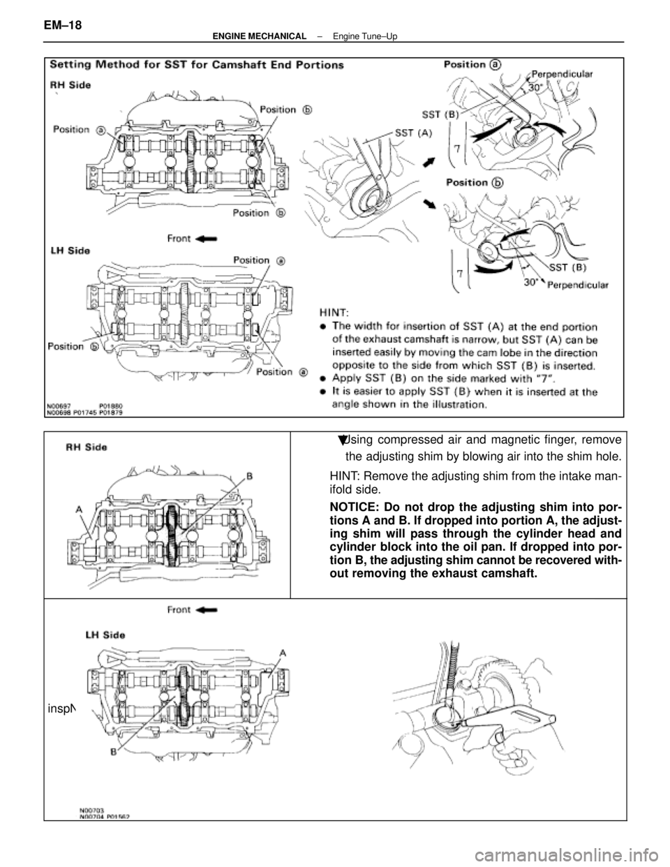
�Using compressed air and magnetic finger, removethe adjusting shim by blowing air into the shim hole.
HINT: Remove the adjusting shim from the intake man-
ifold side.
NOTICE: Do not drop the adjusting shim into por-
tions A and B. If dropped into portion A, the adjust-
ing shim will pass through the cylinder head and
cylinder block into the oil pan. If dropped into por-
tion B, the adjusting shim cannot be recovered with-
out removing the exhaust camshaft.
inspNFO
EM±18±
ENGINE MECHANICAL Engine Tune±Up
WhereEverybodyKnowsYourName
Page 1685 of 4087
 Connect portions A and B engine wire cover to the wirebrackets.
(b) Set the VSV (for fuel pressure control system) wire in
original position.
(c) Fit portio")
35. REINSTALL LH ENGINE WIRE COVER(a) Connect portions A and B engine wire cover to the wirebrackets.
(b) Set the VSV (for fuel pressure control system) wire in
original position.
(c) Fit portions C and D of the engine wire cover, matching them with the lower high±tension cord cover and No.3
timing belt cover.
(d) Install the engine wire cover with the two bolts.
36. REINSTALL UPPER HIGH±TENSION CORD COVER (a) Fit portion A of the upper high±tension cover, matchingthe top of the lower high±tension cord cover.
(b) Push the front side of the upper high±tension cord cover, and connect the front side claw groove of the
upper high±tension cord cover to the claw of the lower
high±tension cord cover.
(c) Install the upper high±tension cord cover with the two bolts.
37. REINSTALL INTAKE AIR CONNECTOR (a) Connect the end portions of the intake air connector tothe throttle body and air cleaner hose.
(b) Tighten the two hose clamps.
(c) Install the bolt holding the intake air connector to the cylinder head cover.
(d) Connect the following hoses: (1) Air hose to ISC to ISC valve
(2) Air hose (from PS air control valve) to intake air connector
EM±26
±
ENGINE MECHANICAL Engine Tune±Up
WhereEverybodyKnowsYourName
 Install the scuff plate.
(h) Connect the connectors.
(i) Install the lower instrument panel finish panel and glovecompartment door assembly with the four screws.
(j) Install the instrument p")
 Remove the two bolts and two nuts, disconnect thethrottle body from the air intake chamber.
(d) Disconnect the following hoses, and remove the throttle body:
(1) PCV hose from throttle body
(2")