Page 2041 of 4087
INSPECTION OF FUEL PUMP
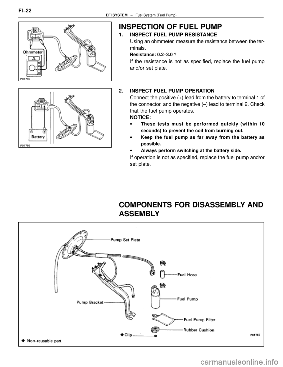
1. INSPECT FUEL PUMP RESISTANCEUsing an ohmmeter, measure the resistance between the ter-
minals.
Resistance: 0.2±3.0 �
If the resistance is not as specified, replace the fuel pump
and/or set plate.
2. INSPECT FUEL PUMP OPERATION Connect the positive (+) lead from the battery to terminal 1 of
the connector, and the negative (±) lead to terminal 2. Check
that the fuel pump operates.
NOTICE:
w These tests must be performed quickly (within 10
seconds) to prevent the coil from burning out.
w Keep the fuel pump as far away from the battery as
possible.
w Always perform switching at the battery side.
If operation is not as specified, replace the fuel pump and/or
set plate.
COMPONENTS FOR DISASSEMBLY AND
ASSEMBLY
FI±22EFI SYSTEM ± Fuel System (Fuel Pump)
WhereEverybodyKnowsYourName
Page 2050 of 4087
11. REMOVE LH NO.3 TIMING BELT COVER(a) Remove the four mounting bolts.
(b) Disconnect the cord grommet from the timing belt cover,
and remove the timing belt cover.
(c) Remove the cord grommet from the high±tension cord.
12. REMOVE LOWER HIGH±TENSION CORD COVER (a) Disconnect the high±tension cord from the RH ignitioncoil.
(b) D i s c onnect the high±tension cords from the
high±tension cord cover.
(c) Remove the bolt and cord cover.
13. REMOVE THROTTLE BODY (a) Disconnect the following connectors:(1) Throttle position sensor connector
(2) (w/ TRAC) Sub±throttle position sensor connector
(3) (w/ TRAC) Sub±throttle actuator connector
(b) Disconnect the following hoses: (1) Heater water hose from heater water valve FI±29
EFI SYSTEM
± Fuel System (Cold Start Injector)
WhereEverybodyKnowsYourName
Page 2060 of 4087
(4) Heater water hose to heater water valve
(e) Connect the following connectors: (1) Throttle position sensor connector
(2) (w/ TRAC)
Sub±throttle position sensor connector
(3) (w/ TRAC) Sub±throttle actuator connector
5. INSTALL LOWER HIGH±TENSION CORD COVER (a) Connect the end portions of the high±tension cord to the
cord clamps
(b) Install the high±tension cord cover with the bolt.
(c) Install the clamps on the high±tension cords to the
high±tension cord cover.
(d) Connect the high±tension cord to the RH ignition coil.
7. INSTALL RH NO.3 TIMING BELT COVER (a) Install the three gaskets to the timing belt cover.
(b) Fit portion A of the timing belt cover, matching it with the
lower high±tension cord cover.
(c) Install the timing belt cover with the three bolts. FI±39
EFI SYSTEM
± Fuel System (Cold Start Injector)
WhereEverybodyKnowsYourName
Page 2073 of 4087
INSTALLATION OF FUEL PRESSURE
PULSATION DAMPER
(See Components on page FI±35)
1. INSTALL FUEL PRESSURE PULSATION DAMPER (a) In sta ll two ne w ga ske ts, th e No . 1 fu e l pip e an dpulsation damper.
(b) Using SST, torque the pulsation damper.
SST 09612±24014 (09617±24011)
Torque: 41 N Vm (420 kgf Vcm, 30 ft Vlbf)
35 N Vm (350 kgf Vcm, 25 ft Vlbf) for SST
HINT: Use a torque wrench with a fulcrum length of 30 cm
(11.81 in.).
2. INSTALL STARTER (See page ST±5)
Torque: 39 N Vm (400 kgf Vcm, 29 ft Vlbf)
3. (A/T)
INSTALL DIPSTICK GUIDE FOR TRANSMISSION
(a) Install a new O±ring to the dipstick guide.
(b) Apply soapy water to the O±ring.
(c) Connect the dipstick guide end to the tube of the oil pan,
and install the dipstick guide with the bolt.
(d) Install the dipstick.
4. CHECK FOR FUEL LEAKS (See page FI±15)
FI±36
±
EFI SYSTEM Fuel System (Fuel Pressure Pulsation Damper)
WhereEverybodyKnowsYourName
Page 2087 of 4087

Firing order1±8±4±3±6±5±7±2
Spark plugTypeNDPK20R11g
NGK BKR6EP11
Electrode gapNew p")
SERVICE SPECIFICATIONS
SERVICE DATA
Ignition timing8±125 BTDC @ idlegg
(w/ Terminals TE1 and E1 connected)
Firing order1±8±4±3±6±5±7±2
Spark plugTypeNDPK20R11g
NGK BKR6EP11
Electrode gapNew plug STD 1.1 mm 0.043 in.
Used plug Limit 1.3 mm 0.051 in.
High±tensionResistance25 k � per cordg
cord
Ignition coilPrimary coil resistance0.40±0.50 �gy
Secondary coil resistance10.0±14.0 k �
Cam positionResistanceat ±10± +40 5C (14±104 5F)835±1,350 �
sensor
Engine speedResistanceat ±10± +40 5C (14±104 5F)835±1,350 �
sensor
TORQUE SPECIFICATIONS
Part tightenedNVmkgf Vcmft Vlbf
Spark plug X Cylinder head1818013
Cam position sensor X Distributor housing18185 13
Distributor cap X Distributor housing3.839 34 in. Vlbf
Distributor rotor X Camshaft timing pulley3.839 34 in. Vlbf
RH No.2 timing belt cover X Cylinder block (for 12 mm head)16160 12
Drive belt idler pulley X Hydraulic pump37380 27
Engine speed sensor X Oil pump6.46556 in. Vlbf
IG±32±
IGNITION SYSTEM Service Specifications
WhereEverybodyKnowsYourName
Page 2089 of 4087

DESCRIPTION
The ECU is programmed with data for optimum ignition timing under any and a\
ll operating conditions. Using
data provided by sensors which monitor various engine functions (rpm, i\
ntake air volume, engine temperature,
etc.) the microcomputer (ECU) triggers the spark at precisely the right ins\
tant.
The ECU monitors the engine condition by signals from each sensor, calculates the ignition timing and sends
an ignition signal to the igniter. High voltage from the ignition is distributed to each spark plug in th\
e appropriate
order to generate a spark between the electrodes, which ignites the air±fu\
el mixture.
IGNITERS The igniter temporarily interrupts the primary current with the ignition si\
gnal (IGT signal) from the ECU and
generates sparks at the spark plug. Also, as a fail±safe measure, when ignitio\
n occurs, an ignition confirmation
signal (IGF signal) is sent to the ECU.
IGNITION COIL
The ignition coil uses a closed core coil with the primary coil wrapped \
around the core and the secondary
coil wrapped around the primary coil. This allows the generation of a hi\
gh voltage sufficient to cause a spark
to jump across the spark plug gap.
DISTRIBUTORS
This correctly distributes high voltage to the spark plug of each cylind\
er in the specified ignition order.
ENGINE SPEED SENSOR The engine speed sensor detects the crank angle.
CAM POSITION SENSORS The RH and LH cam position sensors detect the cam angle.
IG±2
±
IGNITION SYSTEM Description
WhereEverybodyKnowsYourName
Page 2090 of 4087
PRECAUTIONS
1. Do not leave the ignition switch on for more than 10minutes if the engine will not start.
2. With a tachometer connected to the system, connect the tester probe of the tachometer to terminal IG
of the
check (ºDIAGNOSISº) connector.
HINT:
wAllow the engine to warm up to normal operation
temperature.
w Set the tachometer to the 4±cylinder range.
3. As some tachometers are not compatible with this ignition system, we recommend that you confirm the
compatibility of your unit before use.
4. Never allow the tachometer terminal to touch ground as this could damage the igniter and/or ignition coil.
5. Do not disconnect the battery when the engine is running.
6. Check that the igniter is properly grounded to the body.
±
IGNITION SYSTEM PrecautionsIG±3
WhereEverybodyKnowsYourName
Page 2091 of 4087
SYSTEM CIRCUIT
OPERATION
To maintain the most appropriate ignition timing, the ECU sends a control \
signal so that the igniter sends
current to the ignition coil and the spark plugs produce a spark. IG±4
±
IGNITION SYSTEM System Circuit, Operation
WhereEverybodyKnowsYourName
 Remove the four mounting bolts.
(b) Disconnect the cord grommet from the timing belt cover,
and remove the timing belt cover.
(c) Remove the cord grommet")
 Heater water hose to heater water valve
(e) Connect the following connectors: (1) Throttle position sensor connector
(2) (w/ TRAC)
Sub±throttle position sensor connector
(3) (w/ TRAC) Sub±thro")

1. INSTALL FUEL PRESSURE PULSATION DAMPER (a) In sta ll two ne w ga ske ts, th e No . 1 fu e l pip e an dpulsation da")

