Page 1944 of 4087
(b) Install the cam position sensor connector to the ignitioncoil bracket.
(c) Connect the ignition coil connector.
7. REINSTALL LOWER HIGH±TENSION CORD COVER (See steps 1 to 13 and 16 to 18 on pages FI±39 to 41)FI±89
EFI SYSTEM
± Electronic Control System (Cold Start Injector Time Switch)
WhereEverybodyKnowsYourName
Page 1954 of 4087

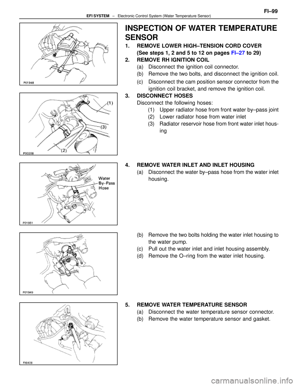
INSPECTION OF WATER TEMPERATURE
SENSOR
1. REMOVE LOWER HIGH±TENSION CORD COVER(See steps 1, 2 and 5 to 12 on pages FI±27 to 29)
2. REMOVE RH IGNITION COIL (a) Disconnect the ignition coil connector.
(b) Remove the two bolts, and disconnect the ignition coil.
(c) Disconnect the cam position sensor connector from the
ignition coil bracket, and remove the ignition coil.
3. DISCONNECT HOSES Disconnect the following hoses:(1) Upper radiator hose from front water by±pass joint
(2) Lower radiator hose from water inlet
(3) Radiator reservoir hose from front water inlet hous-
ing
4. REMOVE WATER INLET AND INLET HOUSING (a) Disconnect the water by±pass hose from the water inlethousing.
(b) Remove the two bolts holding the water inlet housing to the water pump.
(c) Pull out the water inlet and inlet housing assembly.
(d) Remove the O±ring from the water inlet housing.
5. REMOVE WATER TEMPERATURE SENSOR (a) Disconnect the water temperature sensor connector.
(b) Remove the water temperature sensor and gasket. FI±99
EFI SYSTEM
± Electronic Control System (Water Temperature Sensor)
WhereEverybodyKnowsYourName
Page 1955 of 4087

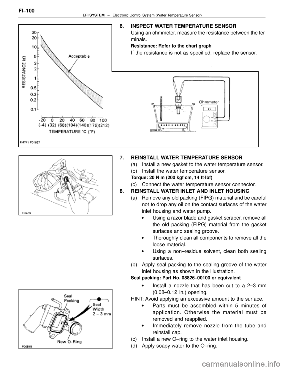
6. INSPECT WATER TEMPERATURE SENSORUsing an ohmmeter, measure the resistance between the ter-
minals.
Resistance: Refer to the chart graph
If the resistance is not as specified, replace the sensor.
7. REINSTALL WATER TEMPERATURE SENSOR (a) Install a new gasket to the water temperature sensor.
(b) Install the water temperature sensor.
Torque: 20 N Vm (200 kgf Vcm, 14 ft Vlbf)
(c) Connect the water temperature sensor connector.
8. REINSTALL WATER INLET AND INLET HOUSING (a) Remove any old packing (FIPG) material and be carefulnot to drop any oil on the contact surfaces of the water
inlet housing and water pump.
w Using a razor blade and gasket scraper, remove all
the old packing (FIPG) material from the gasket
surfaces and sealing groove.
w Thoroughly clean all components to remove all the
loose material.
w Using a non±residue solvent, clean both sealing
surfaces.
(b) Apply seal packing to the sealing groove of the water
inlet housing as shown in the illustration.
Seal packing: Part No. 08826±00100 or equivalent
w Install a nozzle that has been cut to a 2±3 mm
(0.08±0.12 in.) opening.
HINT: Avoid applying an excessive amount to the surface.
w Parts must be assembled within 5 minutes of
application. Otherwise the material must be
removed and reapplied.
w Immediately remove nozzle from the tube and
reinstall cap.
(c) Install a new O±ring to the water inlet housing.
(d) Apply soapy water to the O±ring.
FI±100
EFI SYSTEM
± Electronic Control System (Water Temperature Sensor)
WhereEverybodyKnowsYourName
Page 1956 of 4087
(e) Push in the water inlet housing end into the water pumphole.
(f) Install the water inlet and inlet housing assembly with
the two bolts. Alternately tighten the bolts.
Torque: 18 N Vm (185 kgf Vcm, 13 ft Vlbf)
(g) Connect the water by±pass hose to the water inlet
housing.
9. RECONNECT HOSES Connect the following hoses:(1) Upper radiator hose to front water by±pass joint
(2) Lower radiator hose to water inlet
(3) Radiator reservoir hose to front water inlet housing
10. REINSTALL RH IGNITION COIL (a) Install the ignition coil with the two bolts.
(b) Install the cam position sensor connector to the ignitioncoil bracket.
(c) Connect the ignition coil connector.
11. REINSTALL LOWER HIGH±TENSION CORD COVER (See steps 1 to 13 and 16 to 18 on pages FI±39 to 41)FI±101
EFI SYSTEM
± Electronic Control System (Water Temperature Sensor)
WhereEverybodyKnowsYourName
Page 1977 of 4087
Preparation
SST (SPECIAL SERVICE TOOLS)
IllustrationPart No.Part NameNote
09268±41045Injection Measuring
Tool Set
(90268±41070)No. 4 Union
Injector
(09268±41080)No. 6 Union
Cold start Injector
(09268±52010)Injection Measuring
Attachment
Injector
09268±45012EFI Fuel Pressure
Gauge
09612±24014
Steering Gear
Housing Overhaul
Tool Set
(09617±24011)Steering Rack Wrench
Fuel pressure pulsation damper
09631±22020
Power Steering
Hose Nut 14 X 17 mm
Wrench SetFuel line flare nut
09816±30010Oil Pressure
Switch SocketKnock sensor
09842±30055Wire ªGº
EFI Inspection
Cold start Injector
09842±30070Wire ªFº
EFI Inspection
Injector
09843±18020Diagnosis Check
Wire
0990±01000
Engine Control
Computer
Check Harness ªAº
FI±10 ± PreparationEFI SYSTEM
WhereEverybodyKnowsYourName
Page 1993 of 4087
Fuel Cut RPM
INSPECTION OF FUEL CUT RPM
1. WARM UP ENGINEAllow the engine to warm up to normal operating
temperature.
2. CONNECT TACHOMETER Connect the test probe of a tachometer to terminal IG of the
check connector.
NOTICE
w Never allow the tachometer terminal to touch ground as
it could result in damage to the igniter and/or ignition
coil.
w As some tachometers are not compatible with this
ignition system, we recommend that you confirm the
compatibility of yours before use.
3. INSPECT FUEL CUT OPERATION
(a) Increase the engine speed to at least 2,500 rpm.
(b) Check for injector operating noise.
(c) Check that when the throttle lever is released, injectoroperation noise stops momentarily and then resumes.
HINT:
w The vehicle should be stopped.
w Measure with the A/C OFF.
Fuel return rpm: 1,400 rpm
4. REMOVE TACHOMETER
FI±136
± Electronic Control System (Fuel \
Cut RPM)EFI SYSTEM
WhereEverybodyKnowsYourName
Page 1995 of 4087

SERVICE DATA (Cont'd)
Water temp.
sensorResistanceat ±20°C (±4 °F)
at 0 °C (32 °F)
at 20 °C (68 °F)
at 40 °C (104 °F)
at 60 °C (140 °F)
at 80 °C (176 °F)10 ± 20 k �
4 ± 7 k �
2 ± 7 k �
0.9 ± 1.3 k �
0.4 ± 0.7 k �
0.2 ± 0.4 k �
EGR gas
temp.
sensorResistanceat 50°C (112 °F)
at 100 °C (212 °F)
at 150 °C (302 °F)69 ± 89 k �
12 ± 15 k �
2 ± 4 k �
Main oxygen
sensorHeater coil resistance5.1 ± 6.3 �
Sub±oxygen
sensorHeater coil resistance5.1 ± 6.3 �
ECUHINT:
�Perform all voltage and resistance measurements with the ECU connected.
� Verify that the battery voltage in 11 V or above with the ignition switch is ON.
Voltage
TerminalsConditionSTD voltage (V)
BATT ± E1±10 ± 14
IGSW
+B ± E1
+B1
IG SW ON10 ± 14
VC ± E2±4.0 ± 6.0
IDL1E2
Throttle (or sub±throttle) valve fully closed1 or lessIDL1
IDL2 ± E2
IG SW ONThrottle (or sub±throttle) valve fully open10 ± 14
VTA1E2
Throttle (or sub±throttle) valve fully closed0.1 or lessVTA1
VTA 2 ± E2
Throttle (or sub±throttle) valve fully open3.0 ± 6.0
KS ± E1IdlingPulse generation
THA ± E2
THW±E2Idling
Intake air temp. 20
°C (68 °F)1.0 ± 3.0
THW ± E2IdlingEngine coolant temp. 80 °C (176 °F)0.1 ± 1.0
STA ± E1Cranking6.0 or more
#10
#20
E01IG SW ON10 ± 14#20
#30
#40±
E01
E02IdlingPulse generation
IGT1
IGT2
± E1IdlingPulse generation
FI±138EFI SYSTEM
± Service Specifications
WhereEverybodyKnowsYourName
Page 2014 of 4087
PREPARATION
SST (SPECIAL SERVICE TOOLS)
IllustrationPart No.Part NameNote
09268±41045Injection Measuring
Tool Set
(09268±41090)(No. 7 Union)
Injector
(09268±52010)(Injection Measuring
Attachment)
Injector
(09405±09015)(No. 1 Union)
Injector
09268±45012EFI Fuel Pressure
Gauge
09612±24014
Steering Gear
Housing Overhaul
Tool Set
(09617±24011(Steering Rack Wrench)
Fuel pressure pulsation damper
09631±22020
Power Steering
Hose Nut 14 x 17 mm
Wrench SetFuel line flare nut
09816±30010Oil Pressure
Switch Socket
Knock sensor
09842±30070Wire ªFº
EFI Inspection
Injector
09843±18020Diagnosis Check
Wire
09990±01000
Engine Control
Computer Check
Harness ªAº
±
EFI SYSTEM PreparationFI±9
WhereEverybodyKnowsYourName