Page 1530 of 4087
(b) Disconnect the engine wire clamp from the bracket on thestarter.
(c) Remove the nut, and disconnect the starter wire.
(d) Disconnect the starter connector, and remove the starter.
8. REMOVE KNOCK SENSORS
(a) Disconnect the 2 knock sensor connectors.
(b) Using SST, remove the 2 knock sensors.
SST 09816±30010
9. REMOVE WATER BYPASS PIPE
(a) Remove the 2 bolts.
(b) Pull out the water bypass pipe from the water pump.
(c) Remove the O±ring from the water bypass pipe.
10. REMOVE ENGINE WIRE
(a) Disconnect the following connector: wCrankshaft position sensor connector
w Oil pressure switch connector
w Oil level sensor connector
(b) Remove the 3 bolts and engine wire cover from the LH side of the cylinder block.
(c) Remove the 2 bolts and engine wire.
EG±154
±
1UZ±FE ENGINE ENGINE MECHANICAL
WhereEverybodyKnowsYourName
Page 1564 of 4087
(b) Install the engine wire cover with the 3 bolts.
(c) Connect the following connector:wCrankshaft position sensor connector
w Oil pressure switch connector
w Oil level sensor connector
7. INSTALL WATER BYPASS PIPE
(a) Install a new O±ring to the water bypass pipe.
(b) Apply soapy water to the O±ring.
(c) Push the water bypass pipe end into the pipe hole of the water pump.
(d) Install the water bypass pipe with the 2 bolts.
Torque: 18 N Vm (185 kgf Vcm, 13 ft Vlbf)
8. INSTALL KNOCK SENSORS
(a) Using SST, install the 2 knock sensors.
SST 09816±30010
Torque: 44 N Vm (450 kgf Vcm, 33 ft Vlbf)
(b) Connect the 2 knock sensor connectors.
9. INSTALL STARTER
(a) Install the engine wire clamp to the bracket on the starter.
(b) Connect the starter wire with the nut.
(c) Connect the starter connector.
(d) Install the starter with the 2 bolts.
Torque: 39 N Vm (400 kgf Vcm, 29 ft Vlbf)
EG±188±
1UZ±FE ENGINE ENGINE MECHANICAL
WhereEverybodyKnowsYourName
Page 1579 of 4087
34. FILL WITH ENGINE COOLANT
35. FILL WITH ENGINE OIL
36. START ENGINE AND CHECK FOR LEAKS
37. CHECK TRANSMISSION FLUID LEVEL
38. PERFORM ENGINE ADJUSTMENT(See Tune±Up on pages EG±9 to 34)
39. INSTALL ENGINE UNDER COVER
40. INSTALL HOOD
41. PERFORM ROAD TEST Check for abnormal noise, shock slippage, correct shift
points and smooth operation.
42. RECHECK ENGINE COOLANT AND OIL LEVELS
±
1UZ±FE ENGINE ENGINE MECHANICALEG±203
WhereEverybodyKnowsYourName
Page 1585 of 4087
12. REMOVE RADIATOR RESERVOIR TANK(a) Disconnect the coolant level sensor connector.
(b) Disconnect the following hoses:(1) Reservoir hose to water inlet housing
(2) Reservoir hose to radiator
(c) Remove the two bolts and reservoir tank bracket.
(d) Disconnect the reservoir tank from the reservoir tank bracket, and remove the reservoir tank.
13. REMOVE RADIATOR (a) Disconnect the water temperature sensor connector.
(b) Disc onnect the wire clamp (for water temperature
sensor) from the radiator fan shrould.
(c) Disconnect the following hoses: (1) Two oil cooler hoses (for cooling fan) from pipes
(2) Two radiator hoses
EM±120
±
ENGINE MECHANICAL Cylinder Block
WhereEverybodyKnowsYourName
Page 1598 of 4087
(b) Disconnect the wire clamp from the bracket on thestarter.
(c) Remove the nut, and disconnect the wire.
(d) Disconnect the connector, and remove the starter.
8. REMOVE KNOCK SENSORS (a) Disconnect the two knock sensor connectors.
(b) Using SST, remove the two knock sensors.
SST 09816±30010
9. REMOVE WATER BY±PASS PIPE (a) Remove the two bolts.
(b) Pull out the by±pass pipe from the water pump.
(c) Remove the O±ring from the by±pass pipe.
10. REMOVE ENGINE WIRE (a) Disconnect the following connectors:(1) Oil level sensor connector
(2) Oil pressure switch connector
(b) Remove the three bolts and wire cover from the LH side
of the cylinder block.
(c) Remove the two bolts and engine wire.
±
ENGINE MECHANICAL Cylinder BlockEM±133
WhereEverybodyKnowsYourName
Page 1622 of 4087

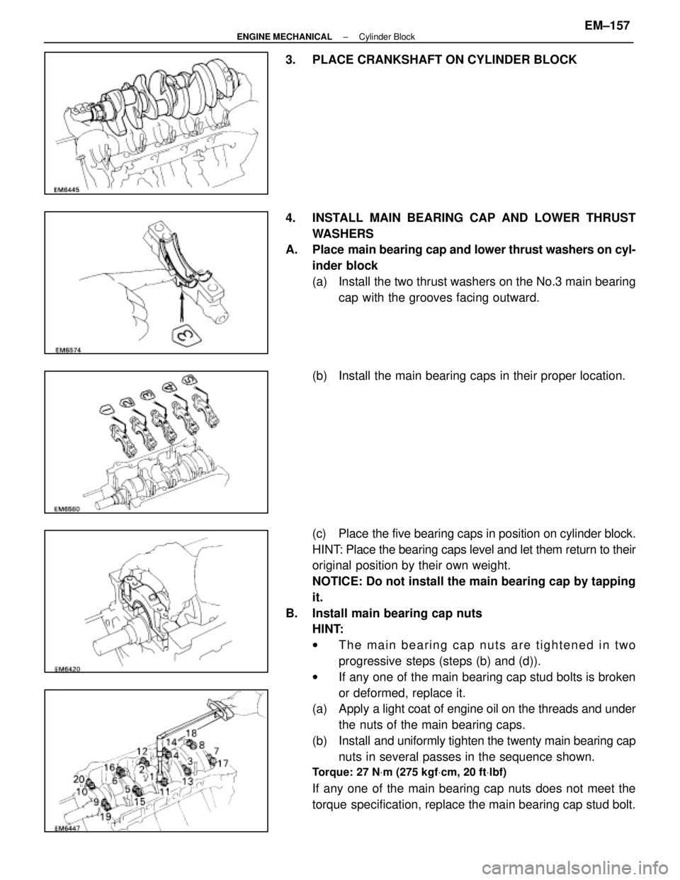
3. PLACE CRANKSHAFT ON CYLINDER BLOCK
4. INSTALL MAIN BEARING CAP AND LOWER THRUSTWASHERS
A. Place main bearing cap and lower thrust washers on cyl-
inder block
(a) Install the two thrust washers on the No.3 main bearing cap with the grooves facing outward.
(b) Install the main bearing caps in their proper location.
(c) Place the five bearing caps in position on cylinder block.
HINT: Place the bearing caps level and let them return to their
original position by their own weight.
NOTICE: Do not install the main bearing cap by tapping
it.
B. Install main bearing cap nuts HINT:
wThe main bearing cap nuts are tightened in two
progressive steps (steps (b) and (d)).
w If any one of the main bearing cap stud bolts is broken
or deformed, replace it.
(a) Apply a light coat of engine oil on the threads and under
the nuts of the main bearing caps.
(b) Install and uniformly tighten the twenty main bearing cap
nuts in several passes in the sequence shown.
Torque: 27 N Vm (275 kgf Vcm, 20 ft Vlbf)
If any one of the main bearing cap nuts does not meet the
torque specification, replace the main bearing cap stud bolt.
±
ENGINE MECHANICAL Cylinder BlockEM±157
WhereEverybodyKnowsYourName
Page 1628 of 4087

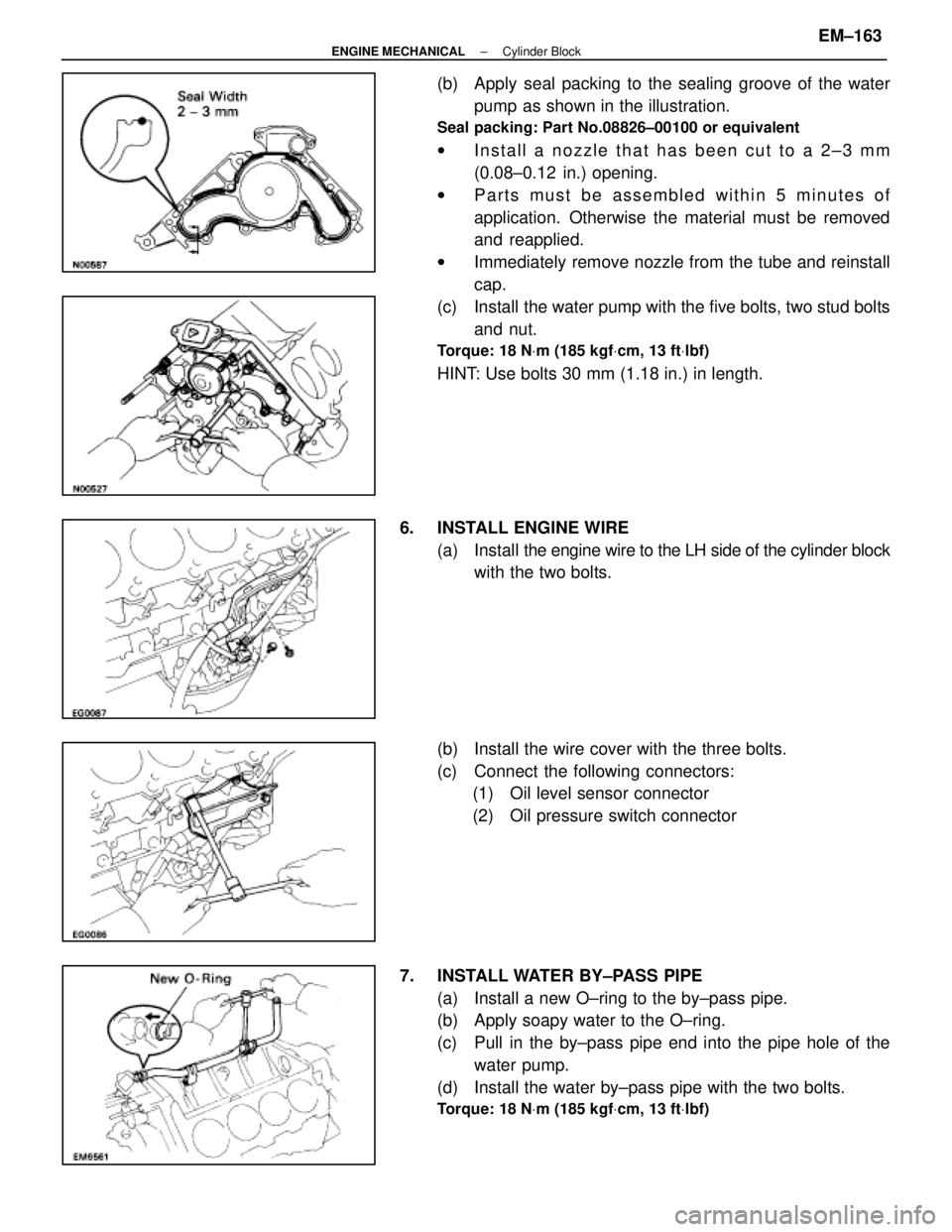
(b) Apply seal packing to the sealing groove of the waterpump as shown in the illustration.
Seal packing: Part No.08826±00100 or equivalent
wInstall a nozzle that has been cut to a 2±3 mm
(0.08±0.12 in.) opening.
w Parts must be assembled within 5 minutes of
application. Otherwise the material must be removed
and reapplied.
w Immediately remove nozzle from the tube and reinstall
cap.
(c) Install the water pump with the five bolts, two stud bolts and nut.
Torque: 18 N Vm (185 kgf Vcm, 13 ft Vlbf)
HINT: Use bolts 30 mm (1.18 in.) in length.
6. INSTALL ENGINE WIRE (a) Install the engine wire to the LH side of the cylinder block
with the two bolts.
(b) Install the wire cover with the three bolts.
(c) Connect the following connectors: (1) Oil level sensor connector
(2) Oil pressure switch connector
7. INSTALL WATER BY±PASS PIPE (a) Install a new O±ring to the by±pass pipe.
(b) Apply soapy water to the O±ring.
(c) Pull in the by±pass pipe end into the pipe hole of thewater pump.
(d) Install the water by±pass pipe with the two bolts.
Torque: 18 N Vm (185 kgf Vcm, 13 ft Vlbf)
±
ENGINE MECHANICAL Cylinder BlockEM±163
WhereEverybodyKnowsYourName
Page 1642 of 4087

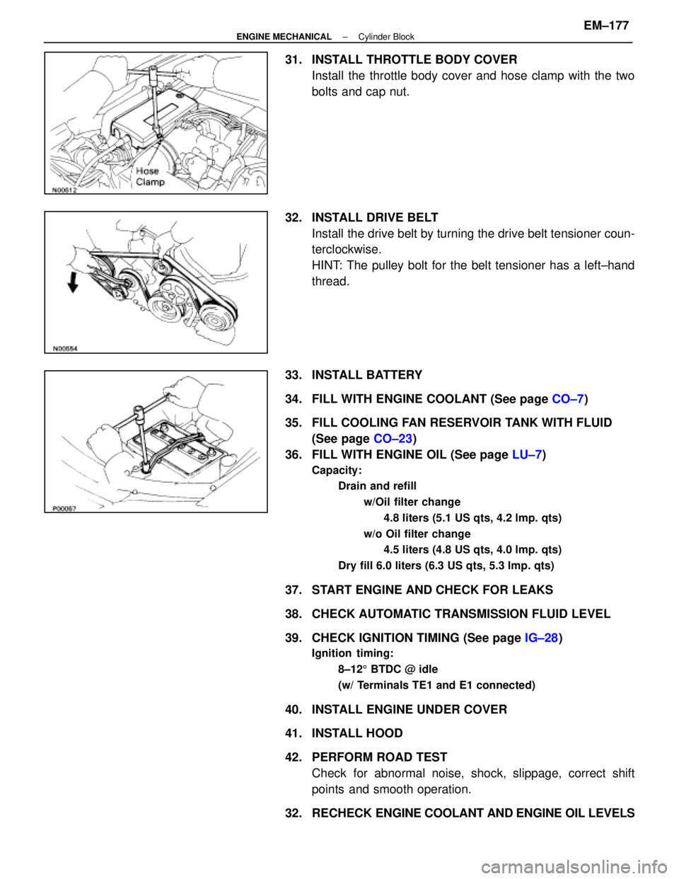
31. INSTALL THROTTLE BODY COVERInstall the throttle body cover and hose clamp with the two
bolts and cap nut.
32. INSTALL DRIVE BELT Install the drive belt by turning the drive belt tensioner coun-
terclockwise.
HINT: The pulley bolt for the belt tensioner has a left±hand
thread.
33. INSTALL BATTERY
34. FILL WITH ENGINE COOLANT (See page CO±7)
35. FILL COOLING FAN RESERVOIR TANK WITH FLUID (See page CO±23)
36. FILL WITH ENGINE OIL (See page LU±7)
Capacity:
Drain and refill
w/Oil filter change4.8 liters (5.1 US qts, 4.2 lmp. qts)
w/o Oil filter change 4.5 liters (4.8 US qts, 4.0 lmp. qts)
Dry fill 6.0 liters (6.3 US qts, 5.3 lmp. qts)
37. START ENGINE AND CHECK FOR LEAKS
38. CHECK AUTOMATIC TRANSMISSION FLUID LEVEL
39. CHECK IGNITION TIMING (See page IG±28)
Ignition timing:
8±125 BTDC @ idle
(w/ Terminals TE1 and E1 connected)
40. INSTALL ENGINE UNDER COVER
41. INSTALL HOOD
42. PERFORM ROAD TEST Check for abnormal noise, shock, slippage, correct shift
points and smooth operation.
32. RECHECK ENGINE COOLANT AND ENGINE OIL LEVELS
±
ENGINE MECHANICAL Cylinder BlockEM±177
WhereEverybodyKnowsYourName