Page 2398 of 4087
 Check the battery voltage")
If there is no pressure, check the following parts:w Fuses
w EFI main relay
w Fuel pump ECU
w Fuel pump
w Engine & ECT ECU
w Wiring connections
2. CHECK FUEL PRESSURE (a) Check the battery voltage above 12 volts.
(b) Disconnect the cable from the negative (±) terminal ofthe battery.
CAUTION: Work must be started after approx. 20 se-
conds or longer from the time the ignition switch is
turned to the ºLOCKº position and negative (±) terminal
cable is disconnected from the battery.
(c) (Exc. USA Spec.) Remove the filter from the VSV (for EGR system).
(d) Remove the union bolt holding the LH deliver pipe to the
rear fuel pipe. Remove the two gaskets.
HINT:
w Put a suitable container or shop towel under the cold
start injector pipe.
w Slowly loosen the union bolt.
(e) Install the rear fuel pipe and SST (pressure gauge) to the LH delivery pipe with three new gaskets and the
union bolt.
SST 09268±45012
Torque: 39 N Vm (400 kgf Vcm, 29 ft Vlbf)
(f) Wipe off any splattered gasoline.
(g) (Exc. USA Spec.)
Reinstall the filter to the VSV.
(h) Using SST, connect terminals B and FP of the check (ºDIAGNOSISº) connector.
SST 09843±18020
(i) Reconnect the cable to the negative (±) terminal of the
battery.
FI±18
EFI SYSTEM
± Fuel System (Fuel Pump)
WhereEverybodyKnowsYourName
Page 2399 of 4087
 Turn the ignition switch ON.
(k) Measure the fuel pressure.
Fuel pressure: 265±304 kPa(2.7±3.1 kgf/cm
2, 38±44 psi)
If pressure is high, replace the fuel pressure regulator.
If pressure is l")
(j) Turn the ignition switch ON.
(k) Measure the fuel pressure.
Fuel pressure: 265±304 kPa(2.7±3.1 kgf/cm
2, 38±44 psi)
If pressure is high, replace the fuel pressure regulator.
If pressure is low, check the following parts:w Fuel hoses and connections
w Fuel pump
w Fuel filter
w Fuel pressure regulator
(l) Remove SST from the check connector.
SST 09843±18020
(m) Start the engine.
(n) Disconnect the vacuum sensing hose from the fuel pressure regulator, and plug the hose end.
(o) Measure the fuel pressure at idling.
Fuel pressure: 265±304 kPa
(2.7±3.1 kgf/cm
2, 38±44 psi)
(p) Re connect the vacuum sensing hose to the fuel
pressure regulator.
(q) Measure the fuel pressure at idling.
Fuel pressure: 196±235 kPa
(2.0±2.4 kgf/cm
2, 28±34 psi)
If pressure is not as specified, check the vacuum sensing
hose and fuel pressure regulator.
(r) Stop the engine. Check that the fuel pressure remains147 kPa (1.5 kgf/cm
2, 21 psi) or more for 5 minutes after
the engine is turned off.
If pressure is not as specified, check the fuel pump, pressure
regulator and/or injectors.
(s) After checking fuel pressure, disconnect the battery negative (±) cable and carefully remove the SST to
prevent gasoline from splashing.
SST 09268±45012
(t) Connect the rear fuel pipe to the delivery pipe with two new gaskets and the union bolt.
Torque: 39 N Vm (400 kgf Vcm, 29 ft Vlbf)
(u) (Exc. USA spec.)
Reinstall the filter to the VSV.
(v) Reconnect the cable to the negative (±) terminal of the
battery.
(w) Check for fuel leaks. (See page FI±16) FI±19
EFI SYSTEM
± Fuel System (Fuel Pump)
WhereEverybodyKnowsYourName
Page 2403 of 4087

1. REMOVE PUMP SET PLATE FROM FUEL PUMP Disconnect the lead connector from the fuel pump, and re-
move the set plate.
2. REMOVE FUEL PUMP F")
DISASSEMBLY OF FUEL PUMP
(See Components on page FI±22)
1. REMOVE PUMP SET PLATE FROM FUEL PUMP Disconnect the lead connector from the fuel pump, and re-
move the set plate.
2. REMOVE FUEL PUMP FROM PUMP BRACKET (a) Pull out the lower side of the fuel pump from the pumpbracket.
(b) Remove the rubber cushion from the fuel pump.
(c) Disc onnect the fuel hose from the fuel pump, and
remove the fuel pump.
3. REMOVE FUEL PUMP FILTER FROM FUEL PUMP (a) Using a small screwdriver, remove the clip.
(b) Pull out the pump filter.
ASSEMBLY OF FUEL PUMP
(See Components on page FI±22)
1. INSTALL FUEL PUMP FILTER TO FUEL PUMP Install the pump filter with a new clip.
2. INSTALL FUEL PUMP TO FUEL PUMP BRACKET (a) Connect the fuel hose to the outlet port of the fuel pump.
(b) Install the rubber cushion to the fuel pump.
(c) Install the fuel pump by pushing the lower side of the fuel
pump.
3. INSTALL PUMP SET PLATE TO FUEL PUMP Connect the lead connector on the set plate to the fuel pump.FI±23
EFI SYSTEM
± Fuel System (Fuel Pump)
WhereEverybodyKnowsYourName
Page 2442 of 4087
PRECAUTIONS
1. Always use new gaskets when replacing the fuel tank orcomponent part.
2. Apply the proper torque to all parts tightened.
INSPECTION OF FUEL LINES AND
CONNECTIONS
(a) Inspect the fuel lines and connections for cracks,
leakage or deformation.
(b) Inspect the fuel tank vapor vent system hoses and connections for looseness, kinks or damage.
(c) Inspect the fuel tank for deformation, cra cks, fuel
leakage or tank band looseness.
(d) Check the filter neck for damage or fuel leakage.
(e) Ho se an d tu b e c onnections are as shown in the
illustration.
If a problem is found, repair or replace the parts as necessary.
FI±62
EFI SYSTEM
± Fuel System (Fuel Tank and Lines)
WhereEverybodyKnowsYourName
Page 2473 of 4087
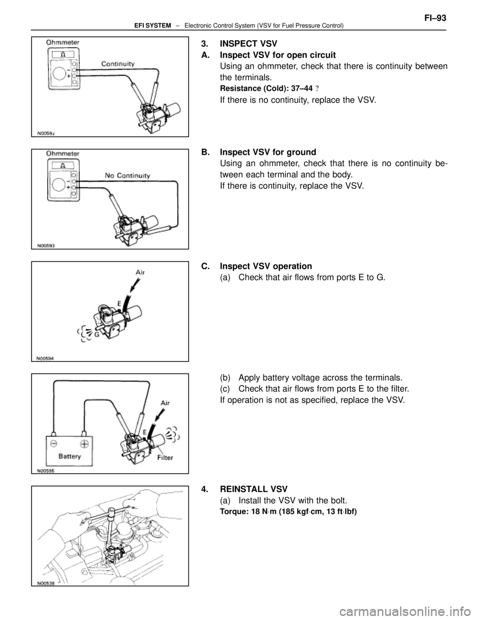
3. INSPECT VSV
A. Inspect VSV for open circuitUsing an ohmmeter, check that there is continuity between
the terminals.
Resistance (Cold): 37±44 �
If there is no continuity, replace the VSV.
B. Inspect VSV for ground Using an ohmmeter, check that there is no continuity be-
tween each terminal and the body.
If there is continuity, replace the VSV.
C. Inspect VSV operation (a) Check that air flows from ports E to G.
(b) Apply battery voltage across the terminals.
(c) Check that air flows from ports E to the filter.
If operation is not as specified, replace the VSV.
4. REINSTALL VSV (a) Install the VSV with the bolt.
Torque: 18 N Vm (185 kgf Vcm, 13 ft Vlbf)
FI±93EFI SYSTEM ± Electronic Control System (VSV for Fuel Pressure Control)
WhereEverybodyKnowsYourName
Page 2860 of 4087
3. VISUALLY INSPECT FUEL TANK CAPCheck if the cap and/or gasket are deformed or damaged.
If necessary, repair or replace the cap.
INSPECTION OF CHARCOAL CANISTER
1. REMOVE CHARCOAL CANISTER(a) Disconnect the following hoses:(1) Vacuum hose (from VSV) from charcoal canister
(2) EVAP hose from charcoal canister
(b) Disconnect the grommet on the check valve from the bracket, and remove the charcoal canister.
(c) Remove the check valve from the hose end on the charcoal canister.
2. VISUALLY INSPECT CHARCOAL CANISTER Look for cracks or damage.
3. CHECK FOR CLOGGED FILTER AND STUCK CHECK VA LV E
(a) Using low pressure compressed air, blow into port A and
check that air flows without resistance from the other
ports.
(b) Blow into port B and check that air does not flow from the
other ports.
If a problem is found, replace the charcoal canister.
±
EMISSION CONTROL SYSTEMS Fuel Evaporative Emission Control (EVAP) SystemEC±9
WhereEverybodyKnowsYourName
Page 2861 of 4087
4. CLEAN FILTER IN CANISTERClean the filter by blowing 294 kPa (3 kgf/cm2, 43 psi) of com-
pressed air into port A while holding port B closed.
NOTICE:
w Do not attempt to wash the canister.
w No activated carbon should come out.
5. REINSTALL CHARCOAL CANISTER
HINT: Install the check valve with black port facing the char-
coal canister side.
(a) Install the check valve to the hose end on the charcoalcanister.
(b) Install the charcoal canister.
(c) Install the grommet on the check valve to the bracket.
(d) Connect the following hoses: (1) Vacuum hose (from VSV) to charcoal canister
(2) EVAP hose to charcoal canister
COMPONENTS FOR REMOVAL AND INSTALLATION OF VSV
EC±10±
EMISSION CONTROL SYSTEMS Fuel Evaporative Emission Control (EVAP) System
WhereEverybodyKnowsYourName
Page 3538 of 4087
OKNG
NGOK
OKNG
INSPECTION PROCEDURE
1Check fuel pump operation.
C
OK
P1. Turn ignition switch ON.
2. Using SST, connect terminals +B and FP of checkconnector.
SST 09843±18020
Check that there is pressure in the hose from the fuel
filter.
Fuel pressure can be felt.
Go to step �.
2Check for open and short in harness and connector between terminals +B e�+B, FP � FP of
the check connector and fuel pump ECU (See page IN±27).
Go to step �.
Repair or replace harness or connector.
3Check voltage of terminal +B of check connector.
C
OK
PTurn ignition switch ON.
Measure voltage between terminal +B of check connec-
tor and body ground.
Voltage: 10 ± 14 V
Check for ECU power source circuit (See page TR±120),
and check for open in harness and connector between
terminal +B of check connector and main relay.
TR±112
±
ENGINE TROUBLESHOOTING Circuit Inspection
WhereEverybodyKnowsYourName
 Inspect the fue")
 Dis")
 of com-
pressed air into port A while holding port B closed.
NOTICE:
w Do not attempt to wash the canister.
w No a")
