Page 1599 of 4087
11. REMOVE WATER PUMP(a) Remove the five mounting bolt, two mounting stud boltsand mounting nut.
(b) Remove the water pump by prying the portions between
the water pump and cylinder block with a screwdriver.
12. REMOVE NO.2 AND NO.1 OIL PANS (See steps 7 to 12 on pages LU±9 to 11)
13. REMOVE OIL PUMP (a) Remove the eight mounting bolts.
(b) Remove the oil pump by prying the portions between the
oil pump and cylinder block with a screwdriver.
(c) Remove the O±ring from the cylinder block.
14. REMOVE ALTERNATOR BRACKET Remove the bolt and bracket.
15. REMOVE WATER SEAL PLATE
Remove the two nuts and seal plate.
EM±134
±
ENGINE MECHANICAL Cylinder Block
WhereEverybodyKnowsYourName
Page 1626 of 4087

POST ASSEMBLY
(See Components on page EM±131)
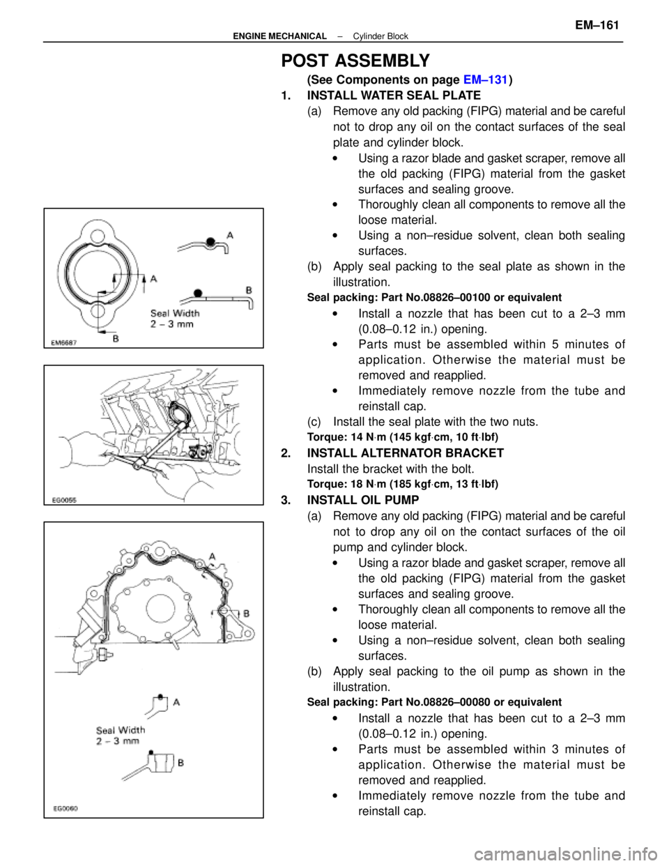
1. INSTALL WATER SEAL PLATE (a) Remove any old packing (FIPG) material and be careful
not to drop any oil on the contact surfaces of the seal
plate and cylinder block.
w Using a razor blade and gasket scraper, remove all
the old packing (FIPG) material from the gasket
surfaces and sealing groove.
w Thoroughly clean all components to remove all the
loose material.
w Using a non±residue solvent, clean both sealing
surfaces.
(b) Apply seal packing to the seal plate as shown in the
illustration.
Seal packing: Part No.08826±00100 or equivalent
w Install a nozzle that has been cut to a 2±3 mm
(0.08±0.12 in.) opening.
w Parts must be assembled within 5 minutes of
application. Otherwise the material must be
removed and reapplied.
w Immediately remove nozzle from the tube and
reinstall cap.
(c) Install the seal plate with the two nuts.
Torque: 14 N Vm (145 kgf Vcm, 10 ft Vlbf)
2. INSTALL ALTERNATOR BRACKET
Install the bracket with the bolt.
Torque: 18 N Vm (185 kgf Vcm, 13 ft Vlbf)
3. INSTALL OIL PUMP
(a) Remove any old packing (FIPG) material and be carefulnot to drop any oil on the contact surfaces of the oil
pump and cylinder block.
w Using a razor blade and gasket scraper, remove all
the old packing (FIPG) material from the gasket
surfaces and sealing groove.
w Thoroughly clean all components to remove all the
loose material.
w Using a non±residue solvent, clean both sealing
surfaces.
(b) Apply seal packing to the oil pump as shown in the
illustration.
Seal packing: Part No.08826±00080 or equivalent
w Install a nozzle that has been cut to a 2±3 mm
(0.08±0.12 in.) opening.
w Parts must be assembled within 3 minutes of
application. Otherwise the material must be
removed and reapplied.
w Immediately remove nozzle from the tube and
reinstall cap.
±
ENGINE MECHANICAL Cylinder BlockEM±161
WhereEverybodyKnowsYourName
Page 1638 of 4087
17. INSTALL PS TUBESInstall the PS tube clamp with the bolt.
18. INSTALL ALTERNATOR (a) Install the alternator and A/T oil cooler pipe bracket withthe bolt and nut.
Torque: 37 N Vm (380 kgf Vcm, 27 ft Vlbf)
(b) Connect the alternator connector.
(c) Connect the alternator wire with the nut and cap.
19. INSTALL WIRE CLAMP (FOR ALTERNATOR) AND VSV (FOR EVAP SYSTEM)
(a) Install the wire clamp to the VSV bracket.
(b) Install the VSV with the two bolts.
20. CONNECT PS SOLENOID VALVE CONNECTOR
21. CONNECT ENGINE WIRE CONNECTORS
22. CONNECT THEFT DETERRENT HORN CONNECTOR
23. INSTALL GROUND CABLE TO BODY
±
ENGINE MECHANICAL Cylinder BlockEM±173
WhereEverybodyKnowsYourName
Page 1713 of 4087
22. REMOVE ALTERNATOR(a) Disconnect the alternator connector.
(b) Remove the cap and nut, and disconnect the alternatorwire.
(c) Remove the bolt, and disconnect the A/T oil cooler pipe bracket.
(d) Remove the nut and alternator.
23. REMOVE DRIVE BELT TENSIONER Remove the bolt, two nuts and tensioner.
24. REMOVE SPARK PLUGS Using a 16 mm plug wrench, remove the eight spark plugs.
25. IF RE±USING TIMING BELT, CHECK INSTALLATION MARKS ON TIMING BELT
Check that there are four installation marks on the timing belt
by turning the crankshaft pulley as shown in the illustration.
If the installation marks have disappeared, place a new
installation mark on the timing belt before removing each
part.
26. SET NO.1 CYLINDER TO TDC/COMPRESSION (a) Turn the crankshaft pulley and align its groove with thetiming mark ºOº of the No.1 timing belt cover.
EM±40
±
ENGINE MECHANICAL Timing Belt
WhereEverybodyKnowsYourName
Page 1725 of 4087

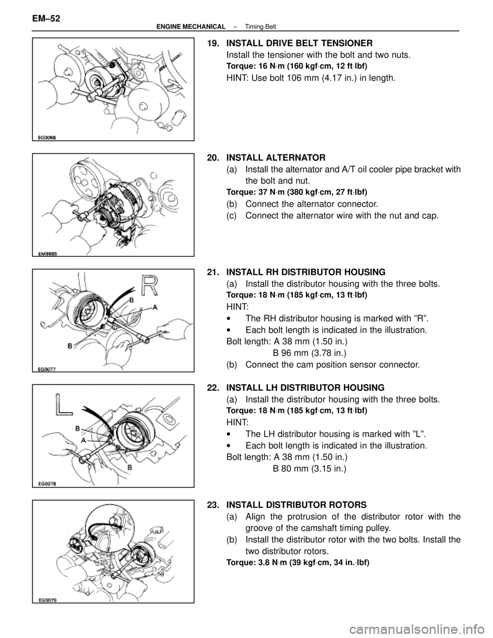
19. INSTALL DRIVE BELT TENSIONERInstall the tensioner with the bolt and two nuts.
Torque: 16 N Vm (160 kgf Vcm, 12 ft Vlbf)
HINT: Use bolt 106 mm (4.17 in.) in length.
20. INSTALL ALTERNATOR (a) Install the alternator and A/T oil cooler pipe bracket withthe bolt and nut.
Torque: 37 N Vm (380 kgf Vcm, 27 ft Vlbf)
(b) Connect the alternator connector.
(c) Connect the alternator wire with the nut and cap.
21. INSTALL RH DISTRIBUTOR HOUSING (a) Install the distributor housing with the three bolts.
Torque: 18 N Vm (185 kgf Vcm, 13 ft Vlbf)
HINT:
w The RH distributor housing is marked with ºRº.
w Each bolt length is indicated in the illustration.
Bolt length: A 38 mm (1.50 in.)
B 96 mm (3.78 in.)
(b) Connect the cam position sensor connector.
22. INSTALL LH DISTRIBUTOR HOUSING (a) Install the distributor housing with the three bolts.
Torque: 18 N Vm (185 kgf Vcm, 13 ft Vlbf)
HINT:
w The LH distributor housing is marked with ºLº.
w Each bolt length is indicated in the illustration.
Bolt length: A 38 mm (1.50 in.)
B 80 mm (3.15 in.)
23. INSTALL DISTRIBUTOR ROTORS (a) Align the protrusion of the distributor rotor with thegroove of the camshaft timing pulley.
(b) Install the distributor rotor with the two bolts. Install the two distributor rotors.
Torque: 3.8 N Vm (39 kgf Vcm, 34 in. Vlbf)
EM±52±
ENGINE MECHANICAL Timing Belt
WhereEverybodyKnowsYourName
Page 2240 of 4087
22. REMOVE ALTERNATOR(a) Disconnect the alternator connector.
(b) Remove the cap and nut, and disconnect the alternatorwire.
(c) Remove the bolt, and disconnect the A/T oil cooler pipe bracket.
(d) Remove the nut and alternator.
23. REMOVE DRIVE BELT TENSIONER Remove the bolt, two nuts and tensioner.
24. REMOVE SPARK PLUGS Using a 16 mm plug wrench, remove the eight spark plugs.
25. IF RE±USING TIMING BELT, CHECK INSTALLATION MARKS ON TIMING BELT
Check that there are four installation marks on the timing belt
by turning the crankshaft pulley as shown in the illustration.
If the installation marks have disappeared, place a new
installation mark on the timing belt before removing each
part.
26. SET NO.1 CYLINDER TO TDC/COMPRESSION (a) Turn the crankshaft pulley and align its groove with thetiming mark ºOº of the No.1 timing belt cover.
EM±40
±
ENGINE MECHANICAL Timing Belt
WhereEverybodyKnowsYourName
Page 2252 of 4087

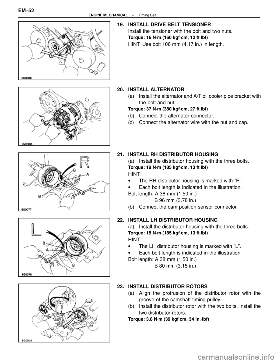
19. INSTALL DRIVE BELT TENSIONERInstall the tensioner with the bolt and two nuts.
Torque: 16 N Vm (160 kgf Vcm, 12 ft Vlbf)
HINT: Use bolt 106 mm (4.17 in.) in length.
20. INSTALL ALTERNATOR (a) Install the alternator and A/T oil cooler pipe bracket withthe bolt and nut.
Torque: 37 N Vm (380 kgf Vcm, 27 ft Vlbf)
(b) Connect the alternator connector.
(c) Connect the alternator wire with the nut and cap.
21. INSTALL RH DISTRIBUTOR HOUSING (a) Install the distributor housing with the three bolts.
Torque: 18 N Vm (185 kgf Vcm, 13 ft Vlbf)
HINT:
w The RH distributor housing is marked with ºRº.
w Each bolt length is indicated in the illustration.
Bolt length: A 38 mm (1.50 in.)
B 96 mm (3.78 in.)
(b) Connect the cam position sensor connector.
22. INSTALL LH DISTRIBUTOR HOUSING (a) Install the distributor housing with the three bolts.
Torque: 18 N Vm (185 kgf Vcm, 13 ft Vlbf)
HINT:
w The LH distributor housing is marked with ºLº.
w Each bolt length is indicated in the illustration.
Bolt length: A 38 mm (1.50 in.)
B 80 mm (3.15 in.)
23. INSTALL DISTRIBUTOR ROTORS (a) Align the protrusion of the distributor rotor with thegroove of the camshaft timing pulley.
(b) Install the distributor rotor with the two bolts. Install the two distributor rotors.
Torque: 3.8 N Vm (39 kgf Vcm, 34 in. Vlbf)
EM±52±
ENGINE MECHANICAL Timing Belt
WhereEverybodyKnowsYourName
Page 2322 of 4087
15. DISCONNECT ENGINE WIRE CONNECTORS
16. DISCONNECT THEFT DETERRENT HORN CONNECTOR
17. DISCONNECT GROUND CABLE FROM BODY
18. DISCONNECT PS SOLENOID VALVE CONNECTOR
19. DISCONNECT WIRE CLAMP (FOR ALTERNATOR) FROMVSV (FOR EVAP SYSTEM)
(a) Remove the two bolts, and disconnect the VSV from the
RH cylinder head.
(b) Disconnect the wire clamp from the VSV bracket.
20. REMOVE ALTERNATOR (a) Disconnect the alternator connector.
(b) Remove the cap and nut, and disconnect the alternatorwire.
(c) Remove the mounting bolt and nut.
(d) Disconnect the A/T oil cooler pipe bracket.
(e) Remove the alternator.
21. D I S C O N N E C T P S T U B E S F R O M S U SPENSION
CROSSMEMBER
Remove the clamp bolt, and disconnect the PS tubes.
EM±122
±
ENGINE MECHANICAL Cylinder Block
WhereEverybodyKnowsYourName