Page 1689 of 4087

COMPRESSION CHECK
HINT: If there is lack of power, excessive oil consumption or
poor fuel economy, measure the compression pressure.
1. WARM UP AND STOP ENGINE Allow the engine to warm up to normal operating tempera-
ture.
2. DISCONNECT DISTRIBUTOR CONNECTOR
3. DISCONNECT HIGH±TENSION CORDS FROM SPARK PLUGS (See steps 2 to 8 on pages EM±10 and 11)
4. DISCONNECT INJECTOR CONNECTORS
5. REMOVE SPARK PLUGS (See page IG±8)
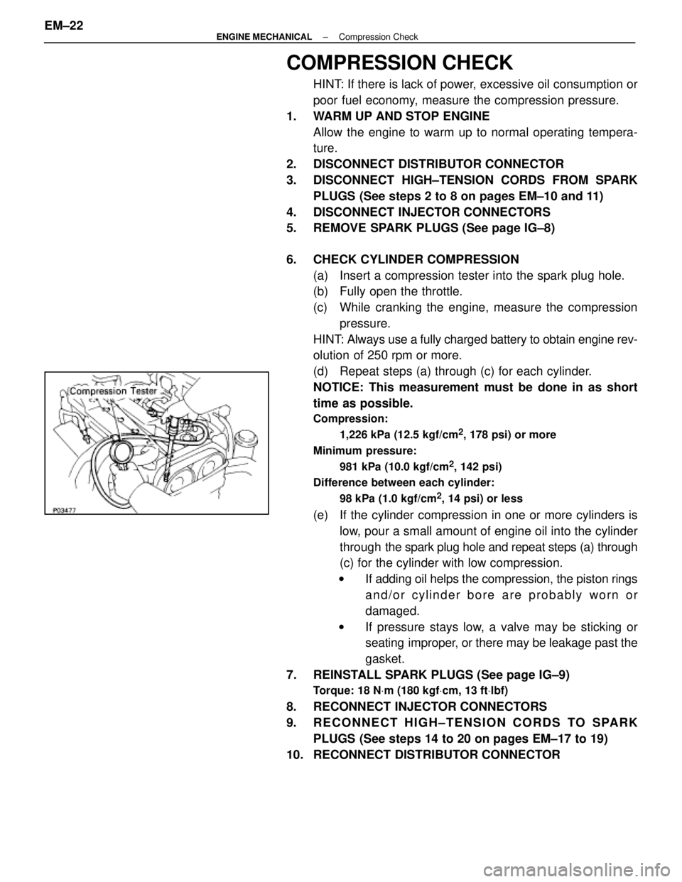
6. CHECK CYLINDER COMPRESSION (a) Insert a compression tester into the spark plug hole.
(b) Fully open the throttle.
(c) While cranking the engine, measure the compressionpressure.
HINT: Always use a fully charged battery to obtain engine rev-
olution of 250 rpm or more.
(d) Repeat steps (a) through (c) for each cylinder.
NOTICE: This measurement must be done in as short
time as possible.
Compression:
1,226 kPa (12.5 kgf/cm
2, 178 psi) or more
Minimum pressure: 981 kPa (10.0 kgf/cm
2, 142 psi)
Difference between each cylinder:
98 kPa (1.0 kgf/cm
2, 14 psi) or less
(e) If the cylinder compression in one or more cylinders islow, pour a small amount of engine oil into the cylinder
through the spark plug hole and repeat steps (a) through
(c) for the cylinder with low compression.
w If adding oil helps the compression, the piston rings
and/or cylinder bore are probably worn or
damaged.
w If pressure stays low, a valve may be sticking or
seating improper, or there may be leakage past the
gasket.
7. REINSTALL SPARK PLUGS (See page IG±9)
Torque: 18 N Vm (180 kgf Vcm, 13 ft Vlbf)
8. RECONNECT INJECTOR CONNECTORS
9. RECONNECT HIGH±TENSION CORDS TO SPARK
PLUGS (See steps 14 to 20 on pages EM±17 to 19)
10. RECONNECT DISTRIBUTOR CONNECTOR
EM±22
±
ENGINE MECHANICAL Compression Check
WhereEverybodyKnowsYourName
Page 1703 of 4087
COMPRESSION CHECK
HINT: If there is lack of power, excessive oil consumption or
poor fuel economy, measure the compression pressure.
1. WARM UP AND STOP ENGINE Allow the engine to warm up to normal operating tempera-
ture.
2. REMOVE NO.3 TIMING BELT COVERS (See steps 1, 5 to 10 and 14 on pages EM±11 to 13)
3. DISCONNECT COLD START INJECTOR CONNECTOR
4. DISCONNECT RH CAM POSITION SENSOR CONNECTOR
(a) Disconnect the connector from the ignition coil bracket.
(b) Disconnect the sensor connector.
5. DISCONNECT LH CAM POSITION SENSOR CONNECTOR
6. REMOVE SPARK PLUGS (a) Disconnect the eight high±tension cords from the sparkplugs.
Disconnect the high±tension cords at rubber boot. Do
not pull on the cords.
NOTICE: Pulling on or bending the cords may damage
the conductor inside.
EM±30
±
ENGINE MECHANICAL Compression Check
WhereEverybodyKnowsYourName
Page 1704 of 4087

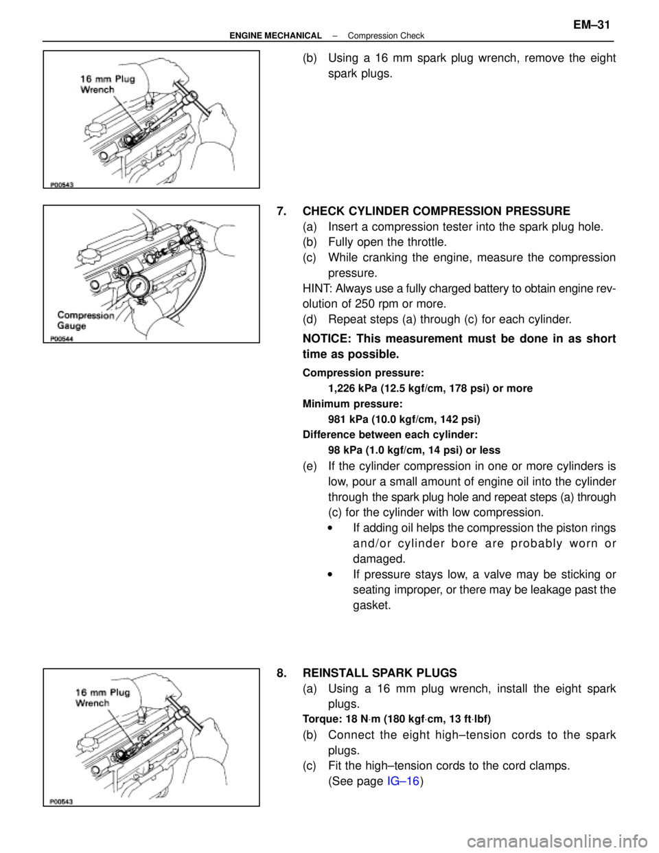
(b) Using a 16 mm spark plug wrench, remove the eightspark plugs.
7. CHECK CYLINDER COMPRESSION PRESSURE (a) Insert a compression tester into the spark plug hole.
(b) Fully open the throttle.
(c) While cranking the engine, measure the compressionpressure.
HINT: Always use a fully charged battery to obtain engine rev-
olution of 250 rpm or more.
(d) Repeat steps (a) through (c) for each cylinder.
NOTICE: This measurement must be done in as short
time as possible.
Compression pressure:
1,226 kPa (12.5 kgf/cm, 178 psi) or more
Minimum pressure: 981 kPa (10.0 kgf/cm, 142 psi)
Difference between each cylinder:
98 kPa (1.0 kgf/cm, 14 psi) or less
(e) If the cylinder compression in one or more cylinders islow, pour a small amount of engine oil into the cylinder
through the spark plug hole and repeat steps (a) through
(c) for the cylinder with low compression.
w If adding oil helps the compression the piston rings
and/or cylinder bore are probably worn or
damaged.
w If pressure stays low, a valve may be sticking or
seating improper, or there may be leakage past the
gasket.
8. REINSTALL SPARK PLUGS (a) Using a 16 mm plug wrench, install the eight sparkplugs.
Torque: 18 N Vm (180 kgf Vcm, 13 ft Vlbf)
(b) C onnect the eight high±tension cords to the spark
plugs.
(c) Fit the high±tension cords to the cord clamps.
(See page IG±16)
±
ENGINE MECHANICAL Compression CheckEM±31
WhereEverybodyKnowsYourName
Page 1711 of 4087
15. REMOVE HIGH±TENSION CORDS, HIGH±TENSIONCORD CLAMPS AND LOWER HIGH±TENSION CORD
COVER ASSEMBLY
(a) Remove the two bolts holding the RH rear high±tensioncord clamp to the cylinder head.
(b) Disconnect the high±tension cords from the RH spark plugs and distributor cap.
(c) Remove the two bolts holding the LH rear high±tension cord clamp to the cylinder head.
(d) Disconnect the high±tension cords from the LH spark
plugs, distributor cap and LH ignition coil.
(e) Remove the bolt holding the lower high±tension cord cover to the water inlet housing.
(f) Disconnect the high±tension cord from the RH ignition
coil, and remove the high±tension cords, clamps and
cover assembly.
16. REMOVE DRIVE BELT IDLER PULLEY Remove the pulley bolt, cover plate and idler pulley.
17. REMOVE RH NO.2 TIMING BELT COVER (a) Disconnect the cam position sensor connector from theignition coil bracket.
EM±38
±
ENGINE MECHANICAL Timing Belt
WhereEverybodyKnowsYourName
Page 1713 of 4087
22. REMOVE ALTERNATOR(a) Disconnect the alternator connector.
(b) Remove the cap and nut, and disconnect the alternatorwire.
(c) Remove the bolt, and disconnect the A/T oil cooler pipe bracket.
(d) Remove the nut and alternator.
23. REMOVE DRIVE BELT TENSIONER Remove the bolt, two nuts and tensioner.
24. REMOVE SPARK PLUGS Using a 16 mm plug wrench, remove the eight spark plugs.
25. IF RE±USING TIMING BELT, CHECK INSTALLATION MARKS ON TIMING BELT
Check that there are four installation marks on the timing belt
by turning the crankshaft pulley as shown in the illustration.
If the installation marks have disappeared, place a new
installation mark on the timing belt before removing each
part.
26. SET NO.1 CYLINDER TO TDC/COMPRESSION (a) Turn the crankshaft pulley and align its groove with thetiming mark ºOº of the No.1 timing belt cover.
EM±40
±
ENGINE MECHANICAL Timing Belt
WhereEverybodyKnowsYourName
Page 1724 of 4087
16. INSTALL TIMING BELT TENSIONER(a) Temporarily install the tensioner with the two bolts.
(b) Alternately tighten the two bolts.
Torque: 26 N Vm (270 kgf Vcm, 20 ft Vlbf)
(c) Using pliers, remove the 1.27 mm hexagon wrench from
the tensioner.
17. CHECK VALVE TIMING (a) Turn the crankshaft pulley two revolutions from TDC toTDC.
NOTICE: Always turn the crankshaft clockwise.
(b) Check that each pulley aligns with the timing marks as shown in the figure.
If the marks do not align, remove the timing belt and reinstall
it.
18. INSTALL SPARK PLUGS Using a 16 mm plug wrench, install the eight spark plugs.
Torque: 18 N Vm (180 kgf Vcm, 13 ft Vlbf)
±
ENGINE MECHANICAL Timing BeltEM±51
WhereEverybodyKnowsYourName
Page 1727 of 4087

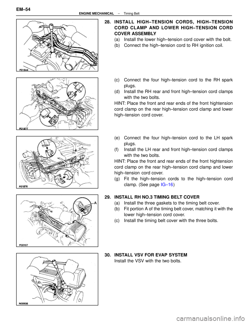
28. INSTALL HIGH±TENSION CORDS, HIGH±TENSIONCORD CLAMP AND LOWER HIGH±TENSION CORD
COVER ASSEMBLY
(a) Install the lower high±tension cord cover with the bolt.
(b) Connect the high±tension cord to RH ignition coil.
(c) Connect the four high±tension cord to the RH sparkplugs.
(d) Install the RH rear and front high±tension cord clamps
with the two bolts.
HINT: Place the front and rear ends of the front hightension
cord clamp on the rear high±tension cord clamp and lower
high±tension cord cover.
(e) Connect the four high±tension cord to the LH spark plugs.
(f) Install the LH rear and front high±tension cord clamps
with the two bolts.
HINT: Place the front and rear ends of the front hightension
cord clamp on the rear high±tension cord clamp and lower
high±tension cord cover.
(g) Fit the high±tension cords to the high±tension cord clamp. (See page IG±16)
29. INSTALL RH NO.3 TIMING BELT COVER (a) Install the three gaskets to the timing belt cover.
(b) Fit portion A of the timing belt cover, matching it with the
lower high±tension cord cover.
(c) Install the timing belt cover with the three bolts.
30. INSTALL VSV FOR EVAP SYSTEM Install the VSV with the two bolts.
EM±54
±
ENGINE MECHANICAL Timing Belt
WhereEverybodyKnowsYourName
Page 1733 of 4087

REMOVAL OF CYLINDER HEAD
(See Components on pages EM±34 and 35)1. DISCONNECT HIGH±TENSION CORDS FROM SPARK PLUGS
(See steps 1 to 8 on pages EM±10 and 11)
2. REMOVE SPARK PLUGS (See step 2 on page IG±8)
3. REMOVE DISTRIBUTOR AND CORDS
(See pages IG±11 and 12)
4. REMOVE WATER PUMP PULLEY AND RADIATOR (See steps 1 to 3, 6 and 7 on pages EM±64 to 66)
5. DISCONNECT TIMING BELT FROM CAMSHAFT TIMING PULLEYS
(See steps 2 to 5 on pages EM±24 and 25)
NOTICE:
wSupport the timing belt, so that the meshing of the
crankshaft timing pulley and timing belt does not shift.
w Be careful not to drop anything inside the timing belt
cover.
w Do not allow the timing belt to come into contact with oil,
water or dust.
6. REMOVE NO. 2 FRONT EXHAUST PIPE (See step 2 on page EM±71)
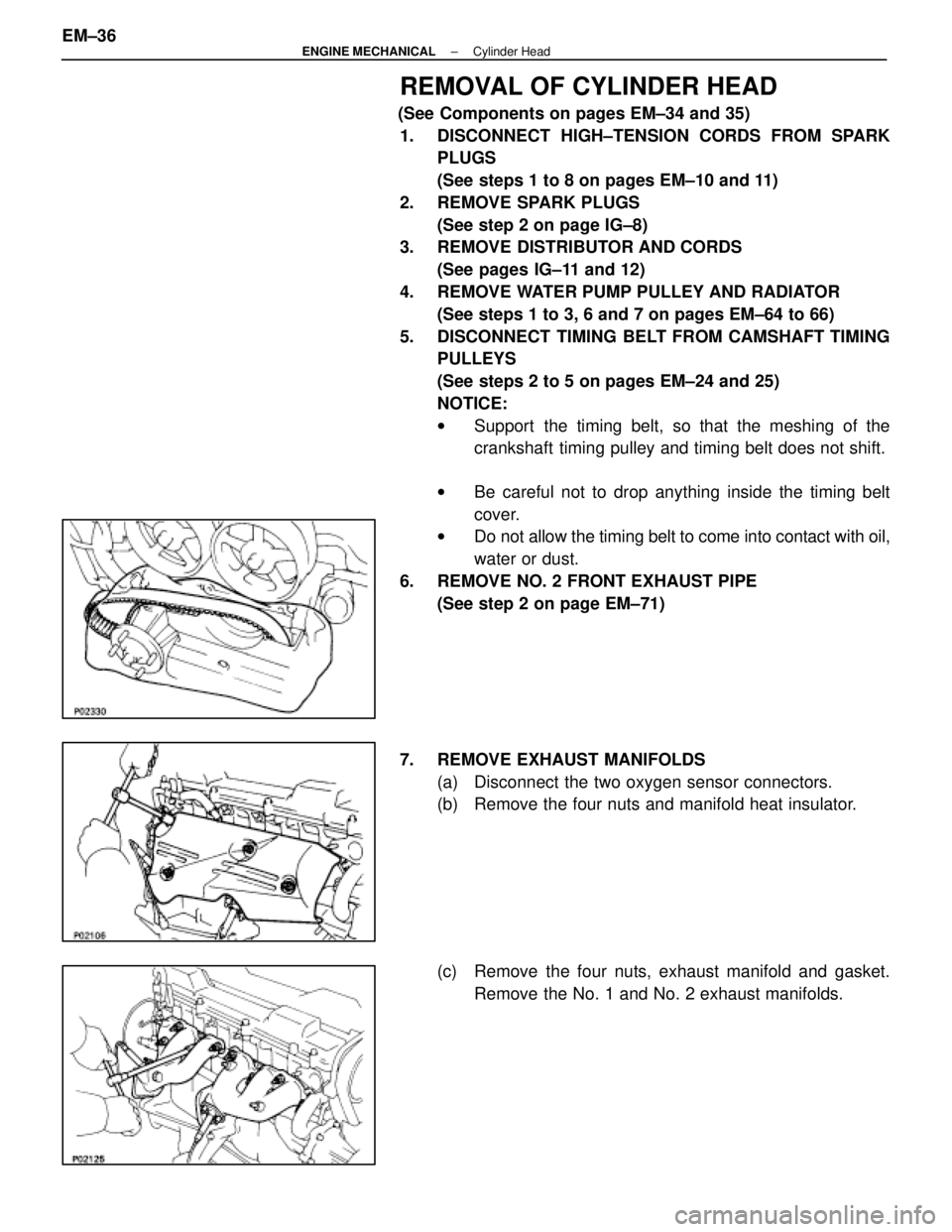
7. REMOVE EXHAUST MANIFOLDS (a) Disconnect the two oxygen sensor connectors.
(b) Remove the four nuts and manifold heat insulator.
(c) Remove the four nuts, exhaust manifold and gasket.Remove the No. 1 and No. 2 exhaust manifolds.
EM±36
±
ENGINE MECHANICAL Cylinder Head
WhereEverybodyKnowsYourName