1991 LEXUS SC300 service
[x] Cancel search: servicePage 38 of 4087
Lexus Supports ASE CertificationPage 1 of 4
Title:
R-12 AIR CONDITIONER SYSTEM
RETROFIT
Models:
'90±'93 ES 250/300, SC 400/300, LS 400
Technical Service
Information Bulletin
April 3, 1998
AC001±98
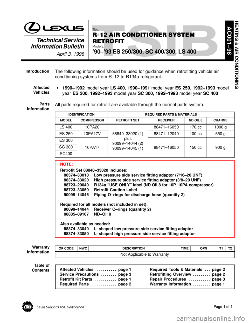
The following information should be used for guidance when retrofitting veh\
icle air
conditioning systems from R±12 to R134a refrigerant.
� 1990±1992 model year LS 400, 1990±1991 model year ES 250, 1992±1993 model
year ES 300, 1992±1993 model year SC 300, 1992±1993 model year SC 400
All parts required for retrofit are available through the normal parts s\
ystem:
IDENTIFICATIONREQUIRED PARTS & MATERIALS
MODELCOMPRESSORRETROFIT SETRECEIVERND OIL 8CHARGE
LS 40010PA2088471±16050170 cc1000 g
ES 25010PA17V88840±33020 (1)
l
88471±12040100 cc650 g
ES 300plus
90099±14044 (2)SC 30010PA1790099±14044 (2)
90099±14045 (1)88471±16050150 cc900 g
SC400
90099 14045 (1)g
NOTE:
Retrofit Set 88840±33020 includes: 88374±33010 Low pressure side service fitting adaptor (7/16±20 UNF)
88374±33020 High pressure side service fitting adaptor (3/8±20 UNF)
88723±20040 R134a ªUSE ONLYº label (ND Oil 8 for 10P, 10PA compressor)
88723±33050 Retrofit Caution Label
90099±14046 Piping O±rings for discharge hose (quantity 2)
Required for all models (not included in set): 90099±14044 Receiver O±rings (quantity 2)
08885±09107 ND±Oil 8
Also available as needed: 88374±33040 L±shaped low pressure side service fitting adaptor
88374±33050 L±shaped high pressure side service fitting adaptor
OP CODENWCDESCRIPTIONTIMEOPNT1T2
Not Applicable to Warranty
Affected Vehicles page 1 . . . . . . . . . .
Service Precautions page 3 . . . . . . . .
Retrofit Kit Parts page 1 . . . . . . . . . . .
Required Parts page 2 . . . . . . . . . . . . . Required Tools & Materials page 2
. . .
Retrofitting Overview page 2 . . . . . . . . .
Repair Procedures page 3 . . . . . . . . . . .
Warranty Information page 1 . . . . . . . . .
HEATING & AIR CONDITIONING
Introduction
Affected
Vehicles
Parts
Information
Warranty
Information
Table of
Contents
WhereEverybodyKnowsYourName
Page 39 of 4087

R±12 AIR CONDITIONER SYSTEM RETROFIT ± AC001±98 April 3, 1998
Page 2 of 4
A. Required Equipment:
1. R±12 recovery/recycling/recharging equipment
2. R134a recovery/recycling/recharging equipment
3. Measuring cylinder (for compressor oil)
4. Valve core remover for service valves
5. Air conditioner service tool set
6. Torque Wrench Set, P/N 00002±50284±01, includes the following*: �14 mm 00002±51410±01
� 17 mm 00002±51710±01
� 22 mm 00002±52216±01
� 27 mm 00002±52724±01
B. Required Parts & Materials: **
1. R134a Refrigerant
2. Service Fitting Adaptors
3. Caution Labels
4. ND±OIL 8 compressor oil (PAG type oil)
5. Receiver
6. O±Rings for compressor, line & hose connections ***
7. Loctite 262 or equivalent
* required size dependent upon model.
** see parts information section of this bulletin on page 1.
*** it is not necessary to replace any O±rings on ES 300, SC 300 and SC 400 models\
.
A. Refrigerant and Oil Charges
�Oil and refrigerant charge amounts are different after the R±12 system has been
retrofitted to R134a. Refrigerant charge amounts are less, while oil ch\
arge
amounts are greater, compared to R±12 system requirements. Refer to the
ND OIL
8
and CHARGE columns in ªParts Informationº table on page 1 for proper amounts\
.
B. System Performance �A slight decrease in system performance may be noticed on some vehicles \
under
certain operating conditions.
C. Refrigerant Pressures
�R134a high side pressures are greater than that of R±12 above ambient\
temperatures of 68 °F.
D. Flushing Requirements �There is no need to remove or flush R±12 mineral oil from the system.\
Simply
charge the system with the specified amount of ND±Oil 8 to provide pr\
oper
lubrication.
E. Use of Sight Glass �Mineral based R±12 oil remains and circulates in the A/C system and d\
oes not
dissolve in R134a refrigerant. This results in a cloudy appearance at th\
e sight
glass making it impossible to judge the refrigerant charge amount by us\
ing the
sight glass method. To prevent misdiagnosis on retrofit vehicles, apply black
paint to the sight glass on block±joint (FF) type Receivers. Union\
±nut joint (BAG)
type retrofit Receivers are manufactured without a sight glass.
Required
Tools &
Materials
Retrofitting Overview
WhereEverybodyKnowsYourName
Page 40 of 4087
R±12 AIR CONDITIONER SYSTEM RETROFIT ± AC001±98 April 3, 1998
Page 3 of 4
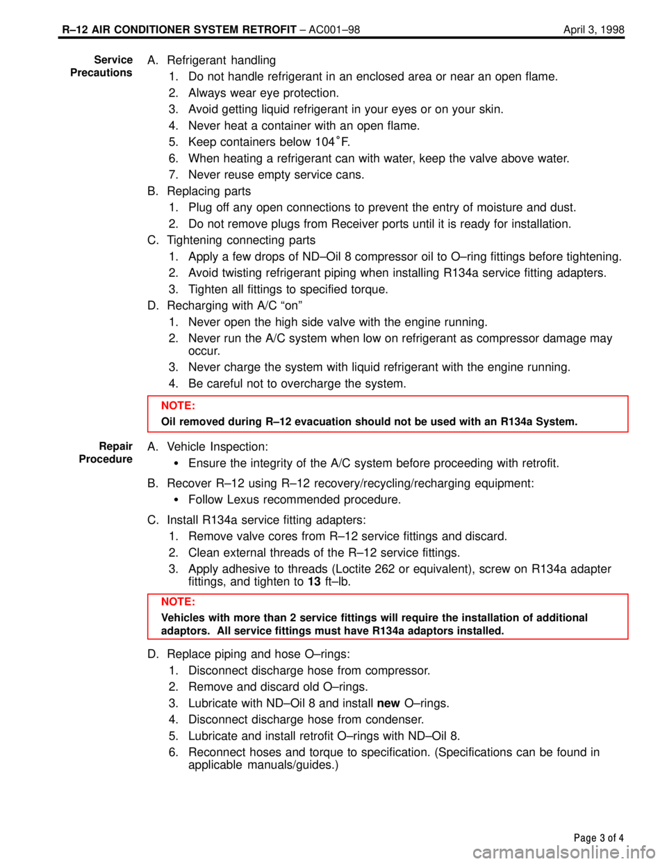
A. Refrigerant handling
1. Do not handle refrigerant in an enclosed area or near an open flame.
2. Always wear eye protection.
3. Avoid getting liquid refrigerant in your eyes or on your skin.
4. Never heat a container with an open flame.
5. Keep containers below 104 °F.
6. When heating a refrigerant can with water, keep the valve above water.
7. Never reuse empty service cans.
B. Replacing parts 1. Plug off any open connections to prevent the entry of moisture and dust.
2. Do not remove plugs from Receiver ports until it is ready for installati\
on.
C. Tightening connecting parts
1. Apply a few drops of ND±Oil 8 compressor oil to O±ring fittings be\
fore tightening.
2. Avoid twisting refrigerant piping when installing R134a service fitting a\
dapters.
3. Tighten all fittings to specified torque.
D. Recharging with A/C ªonº
1. Never open the high side valve with the engine running.
2. Never run the A/C system when low on refrigerant as compressor damage ma\
yoccur.
3. Never charge the system with liquid refrigerant with the engine running.\
4. Be careful not to overcharge the system.
NOTE:
Oil removed during R±12 evacuation should not be used with an R134a Syst\
em.
A. Vehicle Inspection:
�Ensure the integrity of the A/C system before proceeding with retrofit.
B. Recover R±12 using R±12 recovery/recycling/recharging equipment: �Follow Lexus recommended procedure.
C. Install R134a service fitting adapters: 1. Remove valve cores from R±12 service fittings and discard.
2. Clean external threads of the R±12 service fittings.
3. Apply adhesive to threads (Loctite 262 or equivalent), screw on R134a \
adapterfittings, and tighten to 13 ft±lb.
NOTE:
Vehicles with more than 2 service fittings will require the installation \
of additional
adaptors. All service fittings must have R134a adaptors installed.
D. Replace piping and hose O±rings:
1. Disconnect discharge hose from compressor.
2. Remove and discard old O±rings.
3. Lubricate with ND±Oil 8 and install new O±rings.
4. Disconnect discharge hose from condenser.
5. Lubricate and install retrofit O±rings with ND±Oil 8.
6. Reconnect hoses and torque to specification. (Specifications can be fou\
nd in applicable manuals/guides.)
Service
Precautions
Repair
Procedure
WhereEverybodyKnowsYourName
Page 46 of 4087
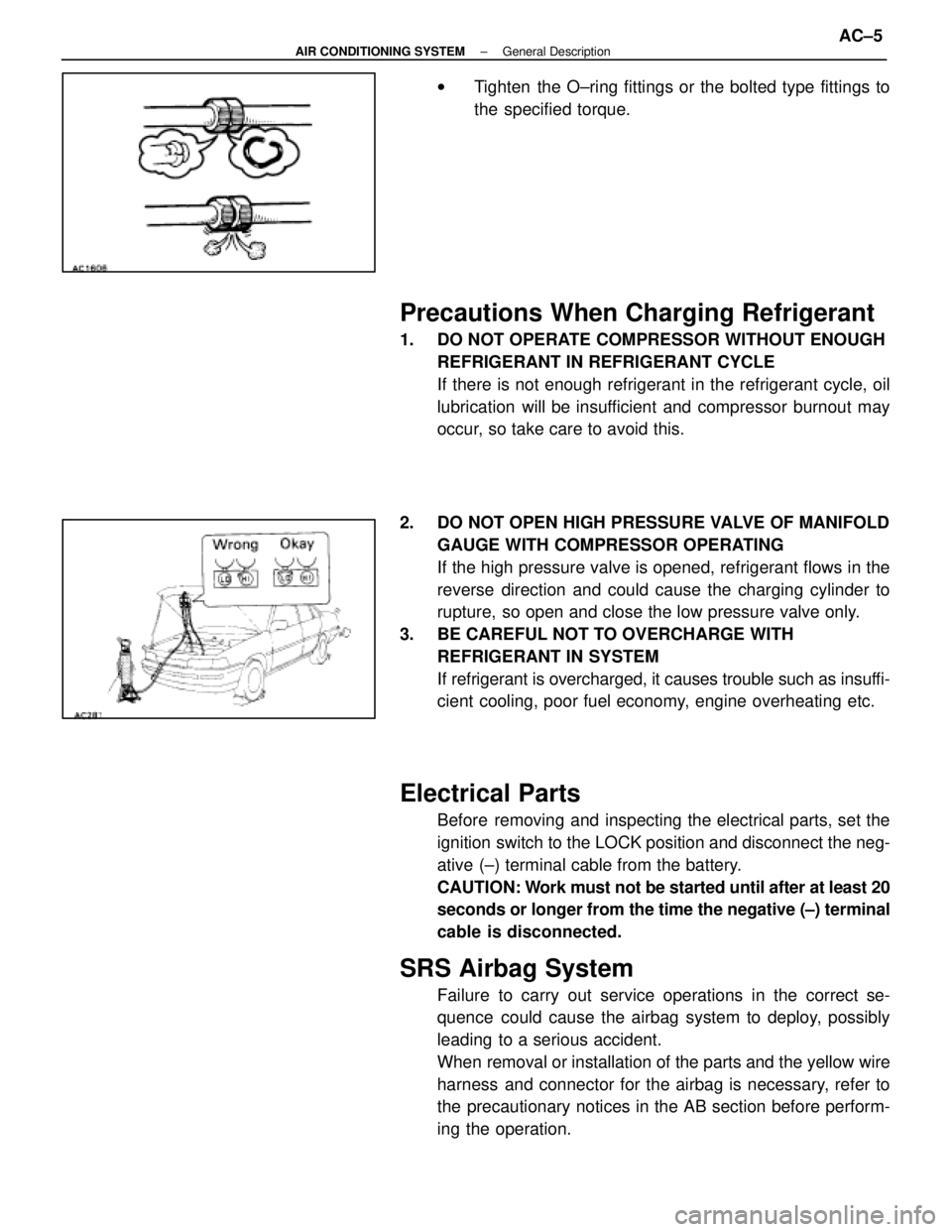
wTighten the O±ring fittings or the bolted type fittings to
the specified torque.
Precautions When Charging Refrigerant
1. DO NOT OPERATE COMPRESSOR WITHOUT ENOUGH
REFRIGERANT IN REFRIGERANT CYCLE
If there is not enough refrigerant in the refrigerant cycle, oil
lubrication will be insufficient and compressor burnout may
occur, so take care to avoid this.
2. DO NOT OPEN HIGH PRESSURE VALVE OF MANIFOLD GAUGE WITH COMPRESSOR OPERATING
If the high pressure valve is opened, refrigerant flows in the
reverse direction and could cause the charging cylinder to
rupture, so open and close the low pressure valve only.
3. BE CAREFUL NOT TO OVERCHARGE WITH REFRIGERANT IN SYSTEM
If refrigerant is overcharged, it causes trouble such as insuffi-
cient cooling, poor fuel economy, engine overheating etc.
Electrical Parts
Before removing and inspecting the electrical parts, set the
ignition switch to the LOCK position and disconnect the neg-
ative (±) terminal cable from the battery.
CAUTION: Work must not be started until after at least 20
seconds or longer from the time the negative (±) terminal
cable is disconnected.
SRS Airbag System
Failure to carry out service operations in the correct se-
quence could cause the airbag system to deploy, possibly
leading to a serious accident.
When removal or installation of the parts and the yellow wire
harness and connector for the airbag is necessary, refer to
the precautionary notices in the AB section before perform-
ing the operation.
±
AIR CONDITIONING SYSTEM General DescriptionAC±5
WhereEverybodyKnowsYourName
Page 54 of 4087
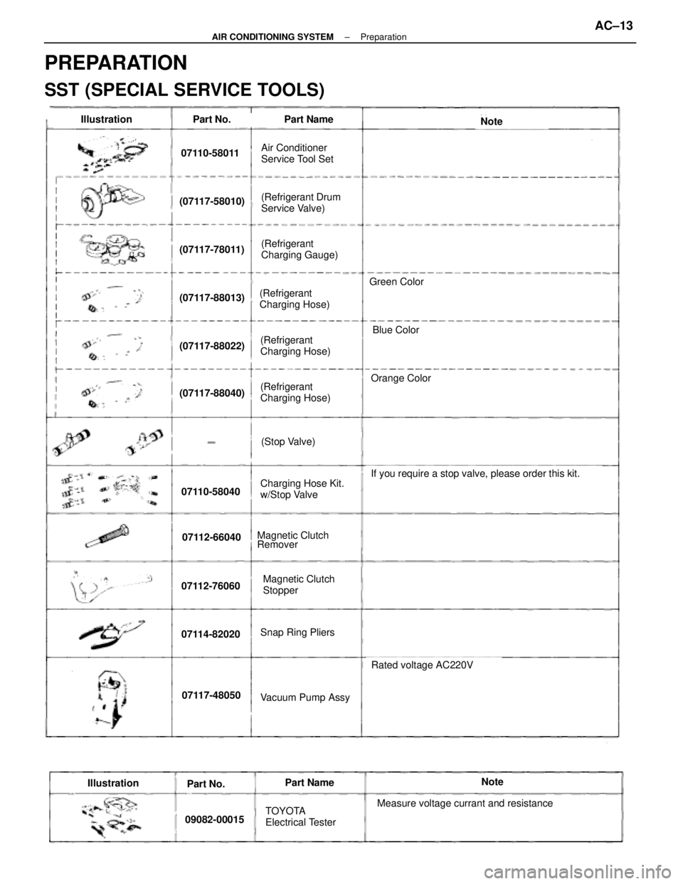
Part No.Part NameNote
07110-58011
(07117-58010)
(07117-78011)
(07117-88013)
(07117-88022)
(07117-88040)
07110-58040
07112-66040
07112-76060
07114-82020
07117-48050
Air Conditioner
Service Tool Set
(Refrigerant Drum
Service Valve)
(Refrigerant
Charging Gauge)
(Refrigerant
Charging Hose)
(Refrigerant
Charging Hose)
(Refrigerant
Charging Hose)
(Stop Valve)
Charging Hose Kit.
w/Stop Valve
Magnetic Clutch
Stopper
Magnetic Clutch
Remover
Snap Ring Pliers
Vacuum Pump Assy
Orange Color
If you require a stop valve, please order this kit.
Rated voltage AC220V
Illustration
IllustrationPart No.Part NameNote
09082-00015TOYOTA
Electrical TesterMeasure voltage currant and resistance
Blue Color
Green Color
PREPARATION
SST (SPECIAL SERVICE TOOLS)
±
AIR CONDITIONING SYSTEM PreparationAC±13
WhereEverybodyKnowsYourName
Page 56 of 4087
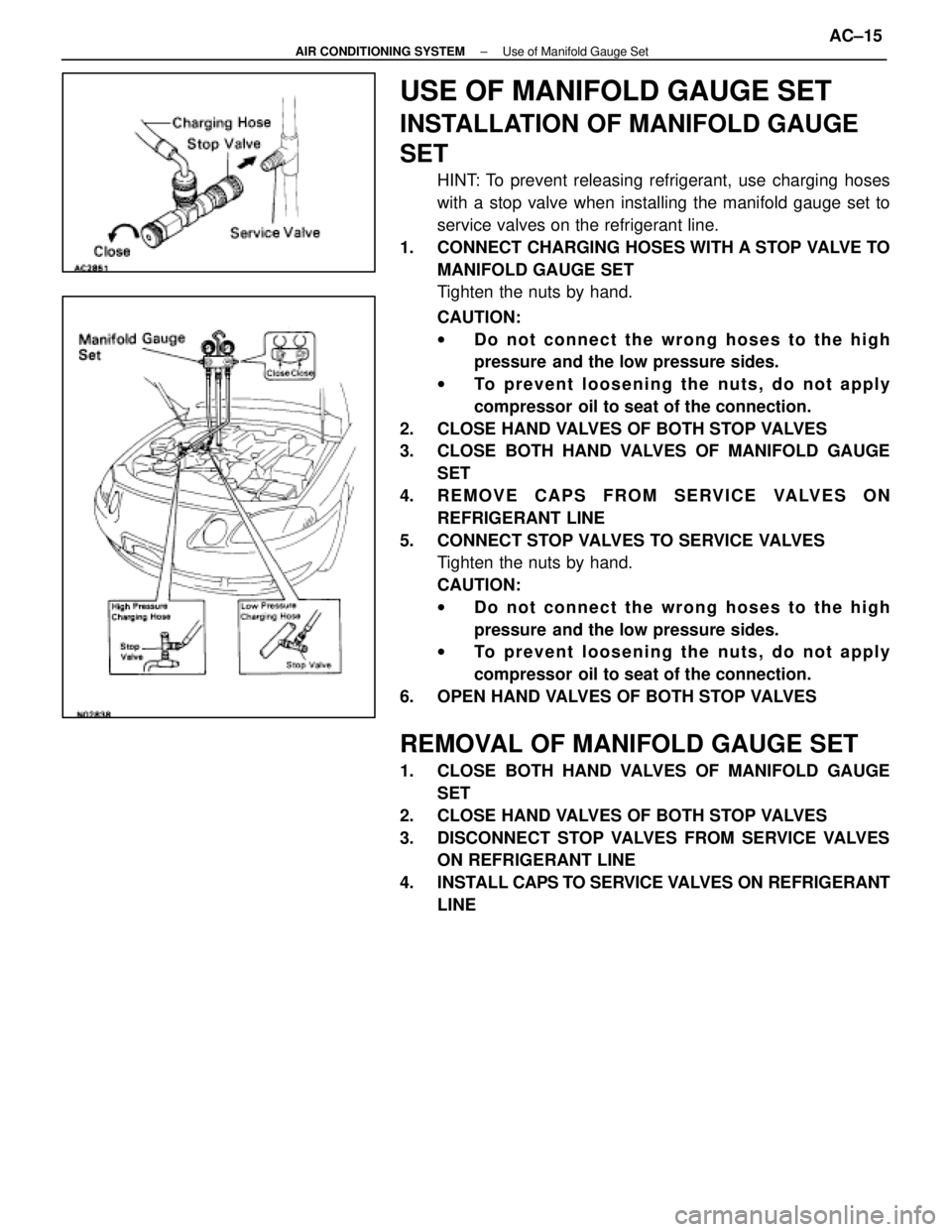
USE OF MANIFOLD GAUGE SET
INSTALLATION OF MANIFOLD GAUGE
SET
HINT: To prevent releasing refrigerant, use charging hoses
with a stop valve when installing the manifold gauge set to
service valves on the refrigerant line.
1. CONNECT CHARGING HOSES WITH A STOP VALVE TO MANIFOLD GAUGE SET
Tighten the nuts by hand.
CAUTION:
wDo not connect the wrong hoses to the high
pressure and the low pressure sides.
w To prevent loosening the nuts, do not apply
compressor oil to seat of the connection.
2. CLOSE HAND VALVES OF BOTH STOP VALVES
3. CLOSE BOTH HAND VALVES OF MANIFOLD GAUGE SET
4. REMOVE CAPS FROM SERVICE VALVES ON REFRIGERANT LINE
5. CONNECT STOP VALVES TO SERVICE VALVES Tighten the nuts by hand.
CAUTION:
wDo not connect the wrong hoses to the high
pressure and the low pressure sides.
w To prevent loosening the nuts, do not apply
compressor oil to seat of the connection.
6. OPEN HAND VALVES OF BOTH STOP VALVES
REMOVAL OF MANIFOLD GAUGE SET
1. CLOSE BOTH HAND VALVES OF MANIFOLD GAUGE SET
2. CLOSE HAND VALVES OF BOTH STOP VALVES
3. DISCONNECT STOP VALVES FROM SERVICE VALVES ON REFRIGERANT LINE
4. INSTALL CAPS TO SERVICE VAL VES ON REFRIGERANT
LINE
±
AIR CONDITIONING SYSTEM Use of Manifold Gauge SetAC±15
WhereEverybodyKnowsYourName
Page 57 of 4087
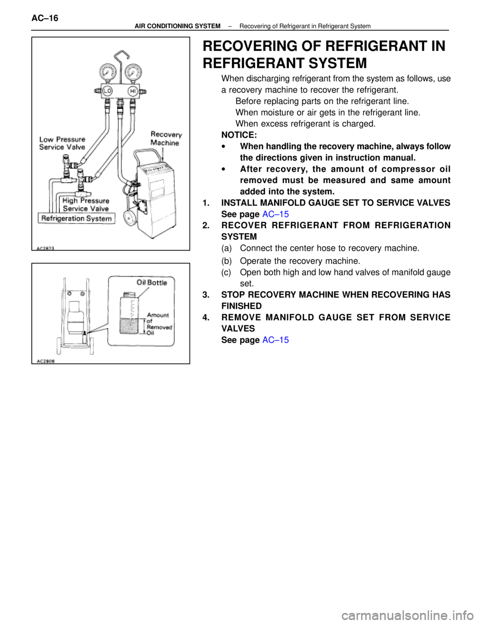
RECOVERING OF REFRIGERANT IN
REFRIGERANT SYSTEM
When discharging refrigerant from the system as follows, use
a recovery machine to recover the refrigerant.Before replacing parts on the refrigerant line.
When moisture or air gets in the refrigerant line.
When excess refrigerant is charged.
NOTICE:
w When handling the recovery machine, always follow
the directions given in instruction manual.
w After recovery, the amount of compr essor oil
removed must be measured and same am ount
added into the system.
1. INSTALL MANIFOLD GAUGE SET TO SERVICE VALVES See page AC±15
2. RECOVER REFRIGERANT FROM REFRIGERATION
SYSTEM
(a) Connect the center hose to recovery machine.
(b) Operate the recovery machine.
(c) Open both high and low hand valves of manifold gauge set.
3. STOP RECOVERY MACHINE WHEN RECOVERING HAS FINISHED
4. REMOVE MANIFOLD GAUGE SET FROM SERVICE VA LV E S
See page AC±15
AC±16
±
AIR CONDITIONING SYSTEM Recovering of Refrigerant in Refrigerant System
WhereEverybodyKnowsYourName
Page 58 of 4087
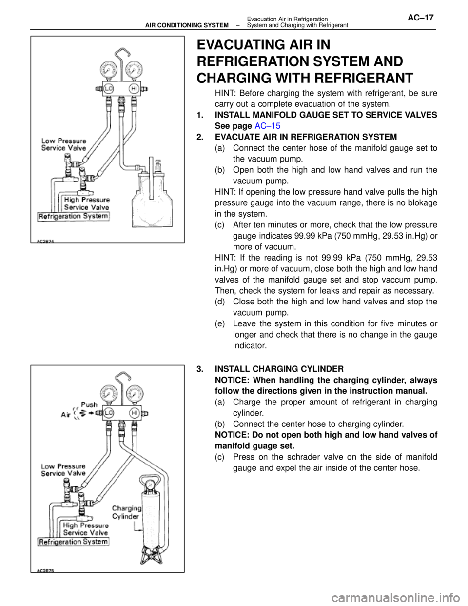
EVACUATING AIR IN
REFRIGERATION SYSTEM AND
CHARGING WITH REFRIGERANT
HINT: Before charging the system with refrigerant, be sure
carry out a complete evacuation of the system.
1. INSTALL MANIFOLD GAUGE SET TO SERVICE VALVES See page AC±15
2. EVACUATE AIR IN REFRIGERATION SYSTEM (a) Connect the center hose of the manifold gauge set to the vacuum pump.
(b) Open both the high and low hand valves and run the vacuum pump.
HINT: If opening the low pressure hand valve pulls the high
pressure gauge into the vacuum range, there is no blokage
in the system.
(c) After ten minutes or more, check that the low pressure gauge indicates 99.99 kPa (750 mmHg, 29.53 in.Hg) or
more of vacuum.
HINT: If the reading is not 99.99 kPa (750 mmHg, 29.53
in.Hg) or more of vacuum, close both the high and low hand
valves of the manifold gauge set and stop vaccum pump.
Then, check the system for leaks and repair as necessary.
(d) Close both the high and low hand valves and stop the
vacuum pump.
(e) Leave the system in this condition for five minutes or longer and check that there is no change in the gauge
indicator.
3. INSTALL CHARGING CYLINDER NOTICE: When handling the charging cylinder, always
follow the directions given in the instruction manual.
(a) Charge the proper amount of refrigerant in charging cylinder.
(b) Connect the center hose to charging cylinder. NOTICE: Do not open both high and low hand valves of
manifold guage set.
(c) Press on the schrader valve on the side of manifold gauge and expel the air inside of the center hose.
±
AIR CONDITIONING SYSTEM Evacuation Air in Refrigeration
System and Charging with RefrigerantAC±17
WhereEverybodyKnowsYourName