Page 529 of 4087
(f) Remove twelve nuts, the front door trim ornament andthe door inside handle.
(g) Remove eight screws and armrest.
(h) Remove the door courtesy light.
4. REMOVE DOOR SPEAKER GRILLE Using a screwdriver, pry loose two clips and remove the cov-
er.
HINT: Tape the screwdriver tip before use.
5. REMOVE DOOR TRIM UPPER PANEL Remove six screws and pry out the panel.
6. REMOVE FRONT DOOR WEATHERSTRIP While pulling the weatherstrip by hand, remove the nine clips
using a clip remover.
HINT: Do not pull strongly on the weatherstrip as it may
tear.
7. REMOVE OUTSIDE REAR VIEW MIRROR AND SPEAKER
(a) Remove two bolts and the speaker, disconnect the connector.
(b) Remove two bolts and the mirror, disconnect the connector.
BO±34
±
BODY Front Door
WhereEverybodyKnowsYourName
Page 535 of 4087
14. INSTALL OUTSIDE REAR VIEW MIRROR(a) Install the mirror with two bolts, connect the connector.
(b) I n s t a l l t h e s peaker with two bolts, connect the
connector.
15. INSTALL FRONT DOOR WEATHERSTRIP Push down on the nine clips of the weatherstrip.
16. INSTALL DOOR TRIM UPPER PANEL (a) Push the panel into the frame.
(b) Tap in the three clips.
(c) Install the panel with six screws.
17. INSTALL DOOR SPEAKER GRILLE Slide the grille and tap the grille to install it.
18. INSTALL DOOR TRIM (a) Install the front door trim ornament and the door insidehandle with eleven nuts.
(b) Install the armrest with eight screws.
(c) Install the door curtesy switch.
(d) Install the two cables as shown.
(e) Connect the connector to the door curtesy switch.
BO±40
±
BODY Front Door
WhereEverybodyKnowsYourName
Page 550 of 4087
LIQUID CRYSTAL INNER MIRROR
SYSTEM
Description
The liquid crystal inner mirror replaces the previous mirror, which mechanically switched between the ªDayº and
ªNightº settings, with liquid crystal inside the mirror which changes the bright\
ness of the mirror surface. The com-
ponent parts of this system and their functions are shown in the table below.
Parts NameFunction
Liquid Crystal Inner
MirrorReceives current from the fuse DOME and changes the surface brightness o\
f the mirror
when switch is operated.
Key Unlock Warning
SwitchOpens the circuit so that the mirror can be operated only when the ignit\
ion key is set.
Parts Location
BE±164±
BODY ELECTRICAL SYSTEM Liquid Crystal Inner Mirror System
WhereEverybodyKnowsYourName
Page 551 of 4087
Wiring and Connector Diagrams
Parts Inspection
(Liquid Crystal Inner Mirror)
REMOVAL AND INSTALLATION OF
LIQUID CRYSTAL INNER MIRROR
(See page BO±44)
INSPECTION OF LIQUID CRYSTAL
INNER MIRROR
INSPECT LIQUID CRYSTAL INNER MIRROR
(a) Using a screw driver, pry out the cover.
(b) Remove two screws and center visor.
(Operation)
(a) Connect the positive (+) lead from the battery to terminal
1 and the negative (±) lead to terminal 2.
±
BODY ELECTRICAL SYSTEM Liquid Crystal Inner Mirror SystemBE±165
WhereEverybodyKnowsYourName
Page 552 of 4087

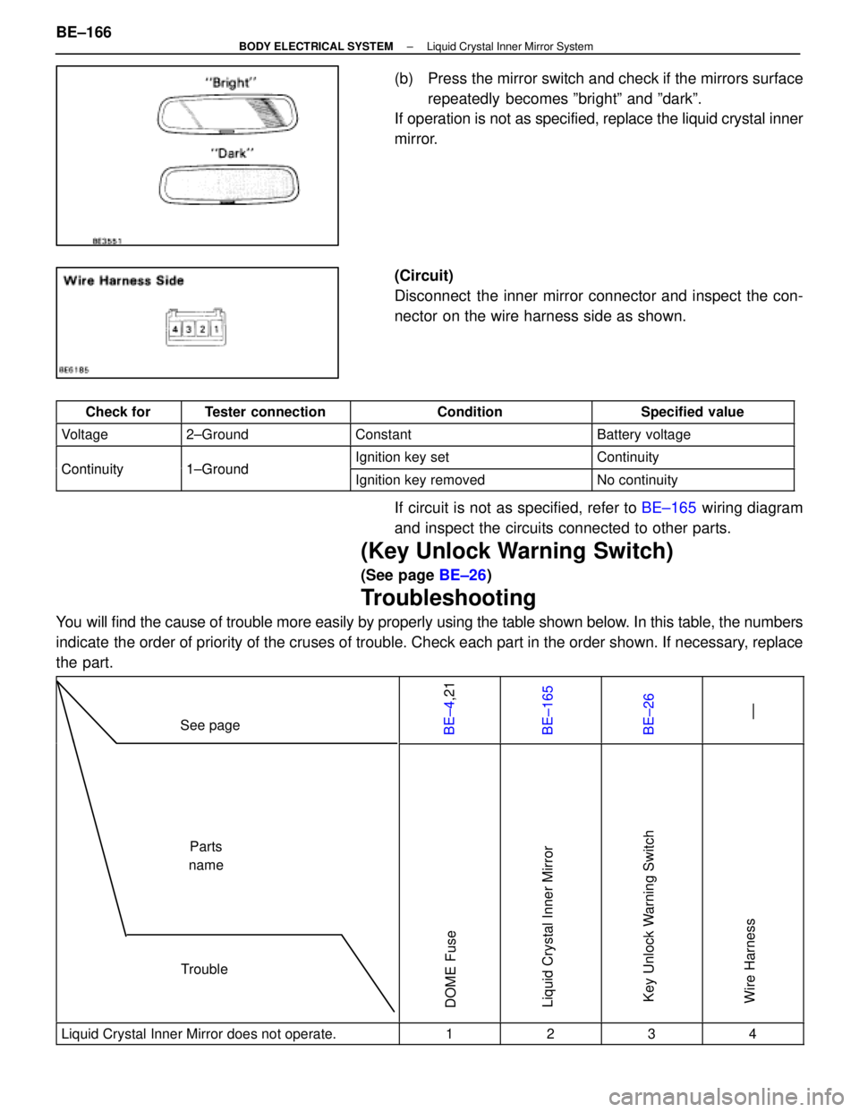
(b) Press the mirror switch and check if the mirrors surfacerepeatedly becomes ºbrightº and ºdarkº.
If operation is not as specified, replace the liquid crystal inner
mirror.
(Circuit)
Disconnect the inner mirror connector and inspect the con-
nector on the wire harness side as shown.
Check forTester connectionConditionSpecified value
Voltage2±GroundConstantBattery voltage
Continuity1 GroundIgnition key setContinuityContinuity1±GroundIgnition key removedNo continuity
If circuit is not as specified, refer to BE±165 wiring diagram
and inspect the circuits connected to other parts.
(Key Unlock Warning Switch)
(See page BE±26)
Troubleshooting
You will find the cause of trouble more easily by properly using the table \
shown below. In this table, the numbers
indicate the order of priority of the cruses of trouble. Check each part in the \
order shown. If necessary, replace
the part.
See pageBE±4,21BE±165BE±26 ±±
TroubleParts
name
DOME FuseLiquid Crystal Inner MirrorKey Unlock Warning SwitchWire Harness
Liquid Crystal Inner Mirror does not operate.1234
BE±166±
BODY ELECTRICAL SYSTEM Liquid Crystal Inner Mirror System
WhereEverybodyKnowsYourName
Page 557 of 4087
DEFOGGER SYSTEM
Description
The component parts of this system and their functions are described in the\
following table.
Parts NameFunction
DefoggerWhen over current flows in the defogger circuit, the Defogger fuse break\
s the circuit
to protect it against damage.
Defogger RelayThis relay is supplied with current from terminal IG1 of ignition switch\
(Ignition switch ON)
and switches large current from the defogger.
A/C Control Panel
Assembly
� Defogger SwitchThe defogger switch is built into the A/C Control Panel Assembly. This switch is
supplied with current from the relay and fuse HTR. Grounds current from \
the defogger
relay, turning the defogger relay ON.
Defogger
� Rear Window
� Outer MirrorThese defoggers generate heat when current is supplied from the defogger\
relay.
Parts Location
±
BODY ELECTRICAL SYSTEM Defogger SystemBE±171
WhereEverybodyKnowsYourName
Page 560 of 4087

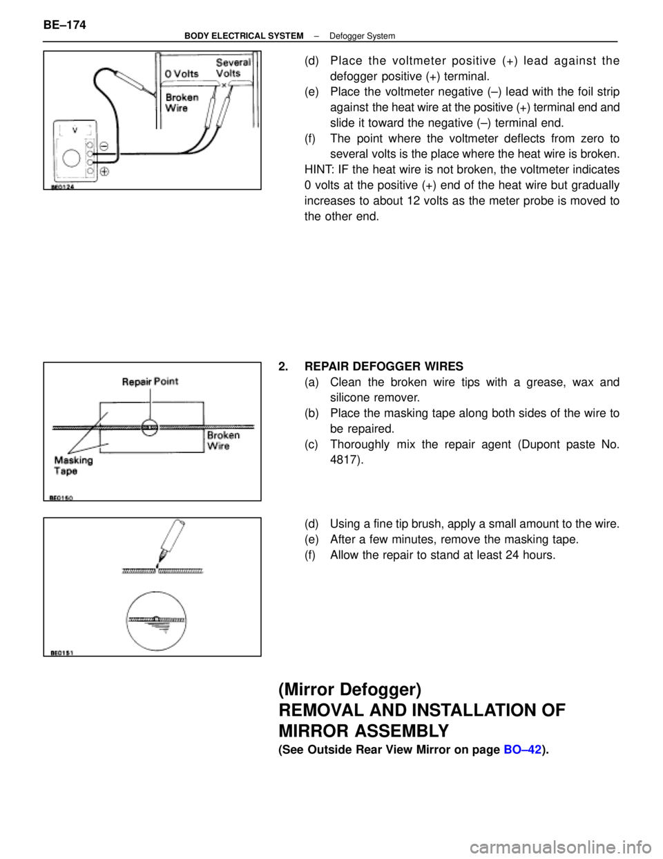
(d) Place the voltmeter positive (+) lead against thedefogger positive (+) terminal.
(e) Place the voltmeter negative (±) lead with the foil strip
against the heat wire at the positive (+) terminal end and
slide it toward the negative (±) terminal end.
(f) The point where the voltmeter deflects from zero to several volts is the place where the heat wire is broken.
HINT: IF the heat wire is not broken, the voltmeter indicates
0 volts at the positive (+) end of the heat wire but gradually
increases to about 12 volts as the meter probe is moved to
the other end.
2. REPAIR DEFOGGER WIRES (a) Clean the broken wire tips with a grease, wax andsilicone remover.
(b) Place the masking tape along both sides of the wire to be repaired.
(c) Thoroughly mix the repair agent (Dupont paste No. 4817).
(d) Using a fine tip brush, apply a small amount to the wire.
(e) After a few minutes, remove the masking tape.
(f) Allow the repair to stand at least 24 hours.
(Mirror Defogger)
REMOVAL AND INSTALLATION OF
MIRROR ASSEMBLY
(See Outside Rear View Mirror on page BO±42).
BE±174
±
BODY ELECTRICAL SYSTEM Defogger System
WhereEverybodyKnowsYourName
Page 561 of 4087
INSPECTION OF MIRROR DEFOGGER
INSPECT MIRROR DEFOGGER(a) Connect the positive (+) lead from the battery to terminal
7 and the negative (±) lead to terminal 8.
(b) Check that the mirror becomes warm.
HINT: It will take a short time for the mirror to become warm.
If the mirror does not become warm, replace the mirror as-
sembly.
Troubleshooting
You will find the cause of trouble more easily using the table shown below. In this table, the number indicate
the order priority of the causes in trouble. Check each part in the order s\
hown. If necessary, replace the parts.
See pageBE±4 ,20BE±4,20BE±4,22BE±172BE±173 ±±BE±173 ±±BE±174
TroubleParts
name
HEATER FuseMIR±HTR FuseDEFOG FuseDefogger SwitchDefogger RelayWire HarnessDefogger WiresCKE CoilMirror Defogger
All defogger systems do not operate.11234
Rear window defogger does not operate.312
Mirror Defogger does not operate.132
±
BODY ELECTRICAL SYSTEM Defogger SystemBE±175
WhereEverybodyKnowsYourName