Page 2162 of 4087
MA04N±01
BRAKES
13. INSPECT BRAKE LINE PIPES AND HOSESHINT: Check in a well lighted area. Check the entire circum-
ference and length of the brake hoses using a mirror as re-
quired. Turn the front whe els fully right or left before checking
the front brake.
(a) Check all brake lines and hoses for: wDamage
w Wear
w Deformation
w Cracks
w Corrosion
w Leaks
w Bends
w Twists
(b) Check all clamps for tightness and connections for leakage.
(c) Check that the hoses and lines are clear of sharp edges, moving parts and the exhaust system.
(d) Check that the lines installed in grommets pass through the center of the grommets.
±
MAINTENANCE (1UZ ± FE)MA±11
WhereEverybodyKnowsYourName
Page 2170 of 4087

GENERAL MAINTENANCE
MA00M±03
There are the maintenance and inspection
items which are considered to be the owner's
responsibility. They can be performed by the
owner or be can have them done at a service
shop. These items include those which should
be checked on a daily basis, those which, in
most cases, do not require (special) tools and
those which are considered to be reasonable
for the owner to perform. Items and procedures
for general maintanance are as follows:
MA00P±04
OUTSIDE VEHICLE
1. TIRES
(a) Check the pressure with a gauge. Adjust ifnecessary.
(b) Check for cuts, damage or excessive wear.
2. WHEEL NUTS Wheel checking the tires, check the nuts for
looseness or for missing nuts. If necessary,
tighten them.
3. TIRE ROTATION It is recommended that tires be rotated every
12,000 km (7,500 miles).
4. WINDSHIELD WIPER BLADES Check for wear or cracks whenever they do not
wipe clean. Replace if necessary.
5. FLUID LEAKS
(a) Check underneath for leaking fuel, oil, water or
other fluid.
(b) If you smell gasoline fumes or notice any leak, have the cause found and corrected.
6. DOORS AND ENGINE HOOD
(a) Check that all doors including the trunk lid operate smoothly, and that all latches lock
securely.
(b) Check that the engine hood secondary latch secures the hood from opening when the
primary latch is released.
MA00R±05
INSIDE VEHICLE
7. LIGHTS
(a) C h e c k t h a t t h e h eadlights, stop lights,
tail±lights, turn signal lights, and other lights
are all working. (b) Check the headlight aiming.
8. WARNING LIGHT AND BUZZERS
Check that all warning lights and buzzers func-
tion properly.
9. HORN Check that it is working.
10. WINDSHIELD GLASS
Check for scratches, pits or abrasions.
11. WINDSHIELD WIPER AND WASHER
(a) Check operation of the wipers and washer.
(b) Check that the wipers do not streak.
12. WINDSHIELD DEFROSTER Check that the air comes out from the defroster
outlet when operating the heater air condition-
er at defroster mode.
13. REAR VIEW MIRROR
Check that it is mounted securely.
14. SUN VISORS Check that they move freely and are mounted
securely.
15. STEERING WHEEL Check that it has the specified freeplay. Be
alert for changes in steering condition, such as
hard steering, excessive freeplay or strange
noise.
16. SEATS
(a) Check that all front seat controls such as seat adjusters, seatback recliner, etc. operate
smoothly.
(b) Check that all latches lock securely in any position.
(c) Check that the locks hold securely in any latched position.
(d) Check that the head restraints move up and
down smoothly and that the locks hold securely
in ay latches position.
(e) For folding±down rear seat backs, check that the latches lock securely.
17. SEAT BELTS
(a) Ch e ck th a t th e se a t be lt syste m su ch as buckles, retractors and anchors operate
properly and smoothly.
(b) Check that the belt webbing is not cut, frayed,
worn or damaged.
18. ACCELERATOR PEDAL Check the pedal for smooth operation and un-
even pedal effort or catching.
±
MAINTENANCE (1UZ ± FE)MA±19
WhereEverybodyKnowsYourName
Page 2699 of 4087

Diag. Code 31Air Flow Meter Circuit
CIRCUIT DESCRIPTION
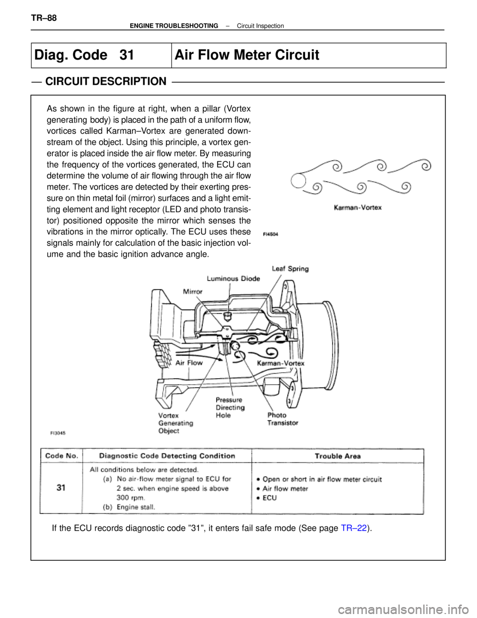
As shown in the figure at right, when a pillar (Vortex
generating body) is placed in the path of a uniform flow,
vortices called Karman±Vortex are generated down-
stream of the object. Using this principle, a vortex gen-
erator is placed inside the air flow meter. By measuring
the frequency of the vortices generated, the ECU can
determine the volume of air flowing through the air flow
meter. The vortices are detected by their exerting pres-
sure on thin metal foil (mirror) surfaces and a light emit-
ting element and light receptor (LED and photo transis-
tor) positioned opposite the mirror which senses the
vibrations in the mirror optically. The ECU uses these
signals mainly for calculation of the basic injection vol-
ume and the basic ignition advance angle.
If the ECU records diagnostic code º31º, it enters fail safe mode \
(See page TR±22).
TR±88
±
ENGINE TROUBLESHOOTING Circuit Inspection
WhereEverybodyKnowsYourName
Page 2759 of 4087

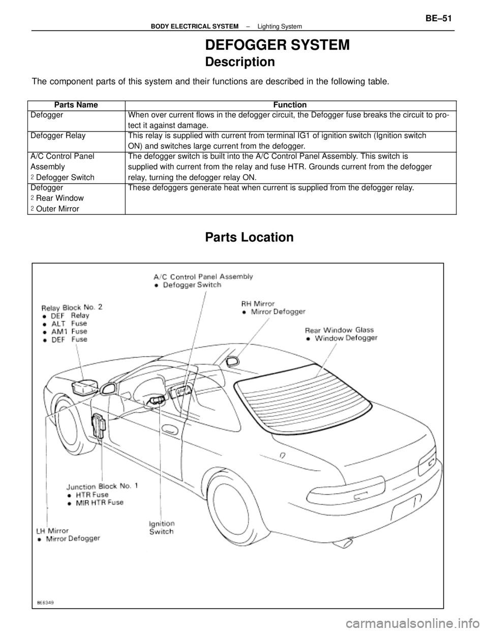
DEFOGGER SYSTEM
Description
The component parts of this system and their functions are described in the\
following table.
��������� ���������Parts Name������������������\
���������� ������������������\
����������Function
��������� ���������Defogger������������������\
���������� ������������������\
����������When over current flows in the defogger circuit, the Defogger fuse break\
s the circuit to pro-
tect it against damage.
��������� �
��������
���������
Defogger Relay������������������\
���������� �
������������������\
���������
������������������\
����������
This relay is supplied with current from terminal IG1 of ignition switch\
(Ignition switch
ON) and switches large current from the defogger.
��������� �
��������
���������
A/C Control Panel
Assembly
�
Defogger Switch������������������\
���������� �
������������������\
���������
������������������\
����������
The defogger switch is built into the A/C Control Panel Assembly. This switch is
supplied with current from the relay and fuse HTR. Grounds current from \
the defogger
relay, turning the defogger relay ON.
��������� �
��������
�
��������
���������
Defogger
�
Rear Window
� Outer Mirror������������������\
���������� �
������������������\
���������
�
������������������\
���������
������������������\
����������
These defoggers generate heat when current is supplied from the defogger\
relay.
Parts Location
±
BODY ELECTRICAL SYSTEM Lighting SystemBE±51
WhereEverybodyKnowsYourName
Page 2762 of 4087

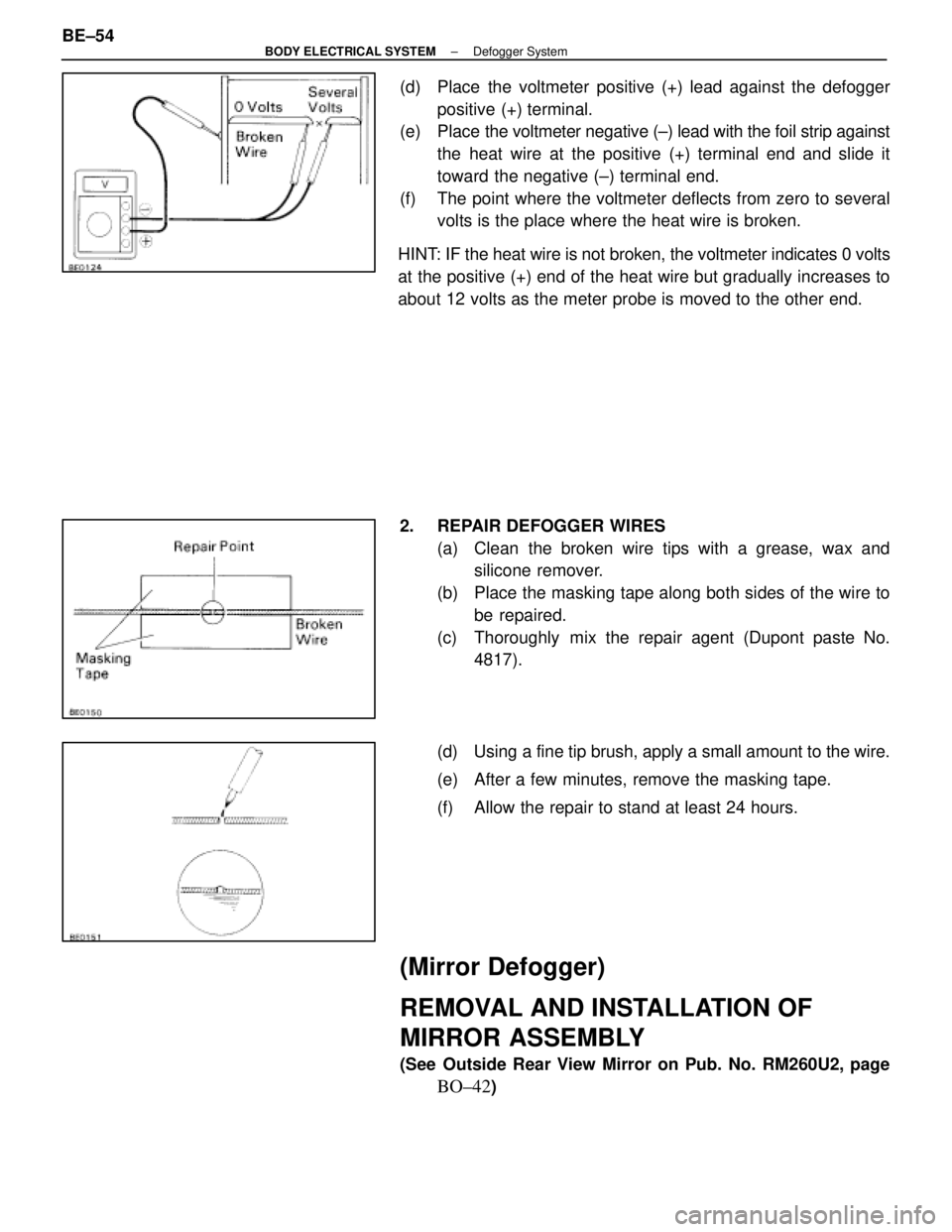
(d) Place the voltmeter positive (+) lead against the defoggerpositive (+) terminal.
(e) Place the voltmeter negative (±) lead with the foil strip against
the heat wire at the positive (+) terminal end and slide it
toward the negative (±) terminal end.
(f) The point where the voltmeter deflects from zero to several volts is the place where the heat wire is broken.
HINT: IF the heat wire is not broken, the voltmeter indicates 0 volts
at the positive (+) end of the heat wire but gradually increases to
about 12 volts as the meter probe is moved to the other end.
2. REPAIR DEFOGGER WIRES (a) Clean the broken wire tips with a grease, wax andsilicone remover.
(b) Place the masking tape along both sides of the wire to be repaired.
(c) Thoroughly mix the repair agent (Dupont paste No. 4817).
(d) Using a fine tip brush, apply a small amount to the wire.
(e) After a few minutes, remove the masking tape.
(f) Allow the repair to stand at least 24 hours.
(Mirror Defogger)
REMOVAL AND INSTALLATION OF
MIRROR ASSEMBLY
(See Outside Rear View Mirror on Pub. No. RM260U2, page
BO±42)
BE±54
±
BODY ELECTRICAL SYSTEM Defogger System
WhereEverybodyKnowsYourName
Page 2763 of 4087
INSPECTION OF MIRROR DEFOGGER
INSPECT MIRROR DEFOGGER
(a) Connect the positive (+) lead from the battery to terminal 7 (4)
and the negative (±) lead to terminal 8 (5).
(b) Check that the mirror becomes warm. HINT: It will take a short time for the mirror to become warm.
If the mirror does not become warm, replace the mirror as-
sembly.
( ): w/o Driving Position Memory
Troubleshooting
You will find the cause of trouble more easily using the table shown belo\
w. In this table, the number indicate
the order priority of the causes in trouble. Check each part in the order s\
hown. If necessary, replace the parts.
� Refer to 1992 LEXUS SC300 Repair Manual (Pub. No. RM260U2)
See pageBE±4 , 20
BE±4 , 20
BE±4 , 22
BE±172
BE±173
BE±173
BE±174
±
BODY ELECTRICAL SYSTEM Defogger SystemBE±55
WhereEverybodyKnowsYourName
Page 2948 of 4087
SR±52).
IN±33).
WIRING DIAGRAM
Set Switch Circuit
CIRCUIT DESCRIPTION
When switch 1 or 2 is pushed while SET switch is being pushed ON in memory o\
peration, a signal is sent
to the ECU to memorize the present positions of the tilt, telescopic, seat\
and mirror.
DIAGNOSTIC CHARTDIAGNOSTIC CHART
SR±88±
STEERING STEERING COLUMN
WhereEverybodyKnowsYourName
Page 2950 of 4087
SR±52).
IN±33).
WIRING DIAGRAM
Memory & Return Switches Circuit
CIRCUIT DESCRIPTION
A memory command signal when switch 1 or 2 pushed while SET
switch is being pushed ON or a return command signal when
switch 1 or 2 is pushed ON is sent to the ECU for memory and re-
turn operations of the tilt, telescopic, seat and mirror.
DIAGNOSTIC CHARTDIAGNOSTIC CHART
SR±90±
STEERING STEERING COLUMN
WhereEverybodyKnowsYourName