1991 FORD FESTIVA wheel bolt torque
[x] Cancel search: wheel bolt torquePage 385 of 454
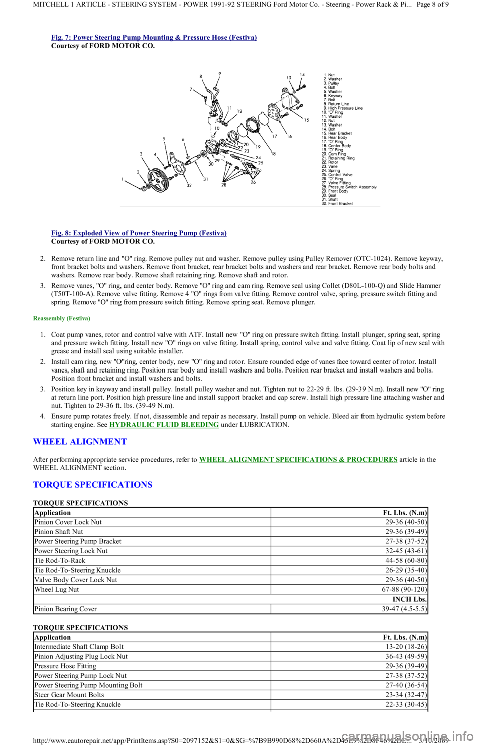
Fig. 7: Power Steering Pump Mounting & Pressure Hose (Festiva)
Courtesy of FORD MOTOR CO.
Fig. 8: Exploded View of Power Steering Pump (Festiva)
Courtesy of FORD MOTOR CO.
2. Remove return line and "O" ring. Remove pulley nut and washer. Remove pulley using Pulley Remover (OTC-1024). Remove keyway,
front bracket bolts and washers. Remove front bracket, rear bracket bolts and washers and rear bracket. Remove rear body bolts and
washers. Remove rear body. Remove shaft retaining ring. Remove shaft and rotor.
3. Remove vanes, "O" ring, and center body. Remove "O" ring and cam ring. Remove seal using Collet (D80L-100-Q) and Slide Hammer
( T5 0 T- 1 0 0 - A) . R e mo ve va l ve fit t in g. R e mo ve 4 "O" r in gs fr o m va l ve fit t in g. R e mo ve c o n t r o l va l ve , sp r in g, p r e ssu r e swit c h fit t ing a n d
spring. Remove "O" ring from pressure switch fitting. Remove spring seat. Remove plunger.
Reassembly (Festiva)
1. Coat pump vanes, rotor and control valve with ATF. Install new "O" ring on pressure switch fitting. Install plunger, spring seat, spring
and pressure switch fitting. Install new "O" rings on valve fitting. Install spring, control valve and valve fitting. Coat lip of new seal with
grease and install seal using suitable installer.
2. Install cam ring, new "O"ring, center body, new "O" ring and rotor. Ensure rounded edge of vanes face toward center of rotor. In st al l
vanes, shaft and retaining ring. Position rear body and install washers and bolts. Position rear bracket and install washers and bolts.
Position front bracket and install washers and bolts.
3. Position key in keyway and install pulley. Install pulley washer and nut. Tighten nut to 22-29 ft. lbs. (29-39 N.m). Install new "O" ring
at return line port. Position high pressure line and install support bracket and cap screw. Install high pressure line attaching washer and
nut. Tighten to 29-36 ft. lbs. (39-49 N.m).
4. Ensure pump rotates freely. If not, disassemble and repair as necessary. Install pump on vehicle. Bleed air from hydraulic system before
starting engine. See HYDRAULIC FLUID BLEEDING
under LUBRICATION.
WHEEL ALIGNMENT
After performing appropriate service procedures, refer to WHEEL ALIGNMENT SPECIFICATIONS & PROCEDURES article in the
WHEEL ALIGNMENT section.
TORQUE SPECIFICATIONS
TORQUE SPECIFICATIONS
TORQUE SPECIFICATIONS
ApplicationFt. Lbs. (N.m)
Pinion Cover Lock Nut29-36 (40-50)
Pinion Shaft Nut29-36 (39-49)
Power Steering Pump Bracket27-38 (37-52)
Power Steering Lock Nut32-45 (43-61)
Tie Rod-To-Rack44-58 (60-80)
Tie Rod-To-Steering Knuckle26-29 (35-40)
Valve Body Cover Lock Nut29-36 (40-50)
Wheel Lug Nut67-88 (90-120)
INCH Lbs.
Pinion Bearing Cover39-47 (4.5-5.5)
ApplicationFt. Lbs. (N.m)
Intermediate Shaft Clamp Bolt13-20 (18-26)
Pinion Adjusting Plug Lock Nut36-43 (49-59)
Pressure Hose Fitting29-36 (39-49)
Power Steering Pump Lock Nut27-38 (37-52)
Power Steering Pump Mounting Bolt27-40 (36-54)
Steer Gear Mount Bolts23-34 (32-47)
Tie Rod-To-Steering Knuckle22-33 (30-45)
Page 8 of 9 MITCHELL 1 ARTICLE - STEERING SYSTEM - POWER 1991-92 STEERING Ford Motor Co. - Steering - Power Rack & Pi
...
3/10/2009 http://www.eautorepair.net/app/PrintItems.asp?S0=2097152&S1=0&SG=%7B9B990D68%2D660A%2D45E9%2D8F46%2DE
...
Page 390 of 454
To reassemble, reverse disassembly procedure.
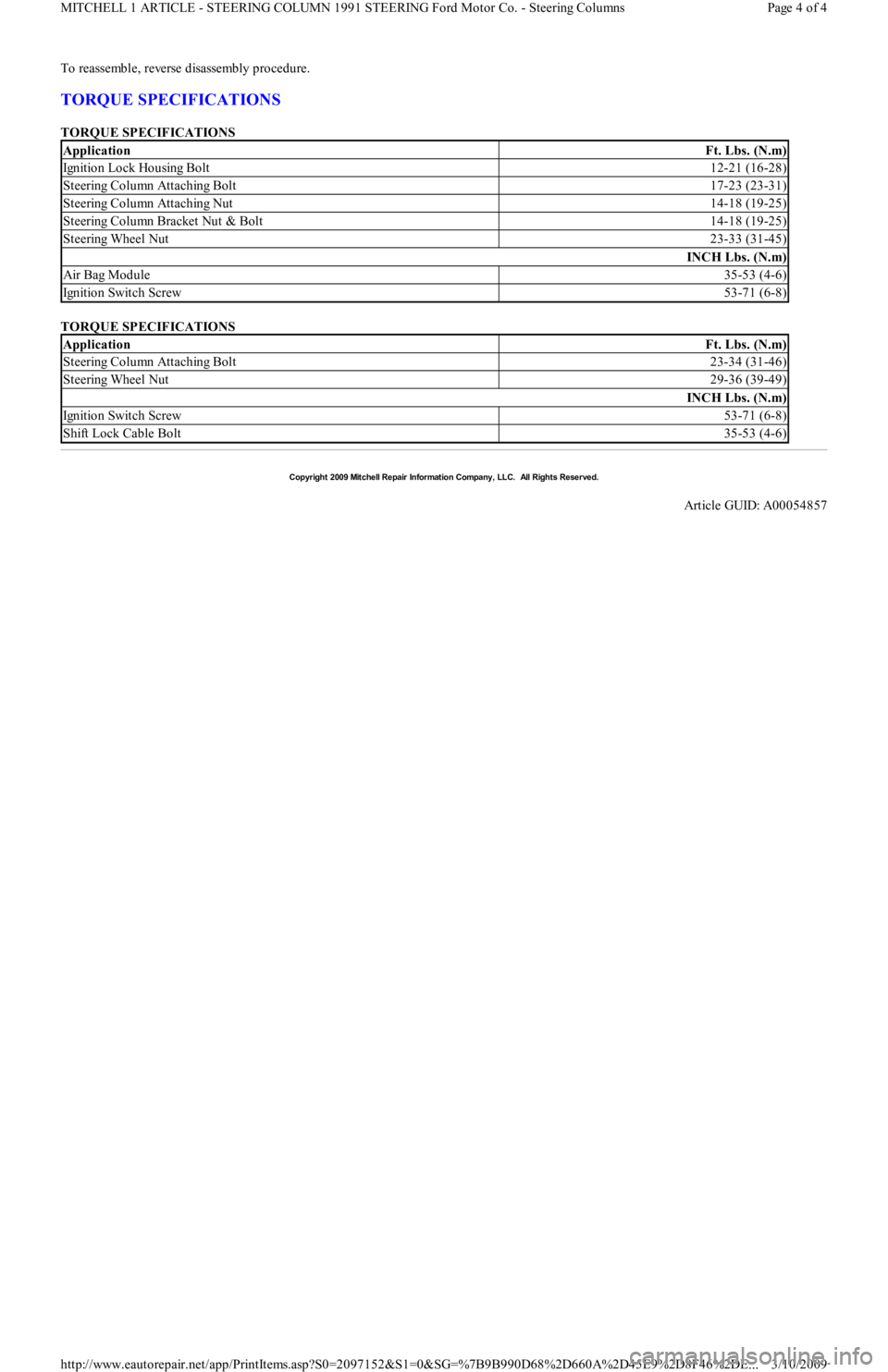
TORQUE SPECIFICATIONS
TORQUE SPECIFICATIONS
TORQUE SPECIFICATIONS
ApplicationFt. Lbs. (N.m)
Ignition Lock Housing Bolt12-21 (16-28)
Steering Column Attaching Bolt17-23 (23-31)
Steering Column Attaching Nut14-18 (19-25)
Steering Column Bracket Nut & Bolt14-18 (19-25)
Steering Wheel Nut23-33 (31-45)
INCH Lbs. (N.m)
Air Bag Module35-53 (4-6)
Ignition Switch Screw53-71 (6-8)
ApplicationFt. Lbs. (N.m)
Steering Column Attaching Bolt23-34 (31-46)
Steering Wheel Nut29-36 (39-49)
INCH Lbs. (N.m)
Ignition Switch Screw53-71 (6-8)
Shift Lock Cable Bolt35-53 (4-6)
Copyr ight 2009 Mitchell Repair Information Company, LLC. All Rights Reserved.
Article GUID: A00054857
Page 4 of 4 MITCHELL 1 ARTICLE - STEERING COLUMN 1991 STEERING Ford Motor Co. - Steering Columns
3/10/2009 http://www.eautorepair.net/app/PrintItems.asp?S0=2097152&S1=0&SG=%7B9B990D68%2D660A%2D45E9%2D8F46%2DE
...
Page 393 of 454
Removal
1. Remove hub and knuckle assembly from vehicle. See HUB & KNUCKLE ASSEMBLY under REMOVAL & INSTALLATION. Using
Knuckle Puller (T87C-1104-A), or a press and bearing puller, remove drive hub/rotor assembly from steering knuckle/dust shield
assembly.
2. Remove bearing preload spacer from hub. Spacer is preselected to provide correct bearing preload. Ensure correct spacer is installed
during reassembly. Install hub/rotor assembly in a vise. Scribe alignment marks on hub and rotor for reassembly reference.
3. Remove rotor attaching bolts and rotor. Use Bearing Splitter (D84L-1123-A), Shaft Protector (D80L-625-2) and a press, or Bearing
Puller (D80L-927-A) and Puller Attachment (D84L-1123-A) to remove outer bearing from wheel hub. Remove and discard outer and
inner grease seals. Using Bearing Puller (T77F-1102-A) and Slide Hammer (T-50T-100-A), remove races from steering knuckle. See
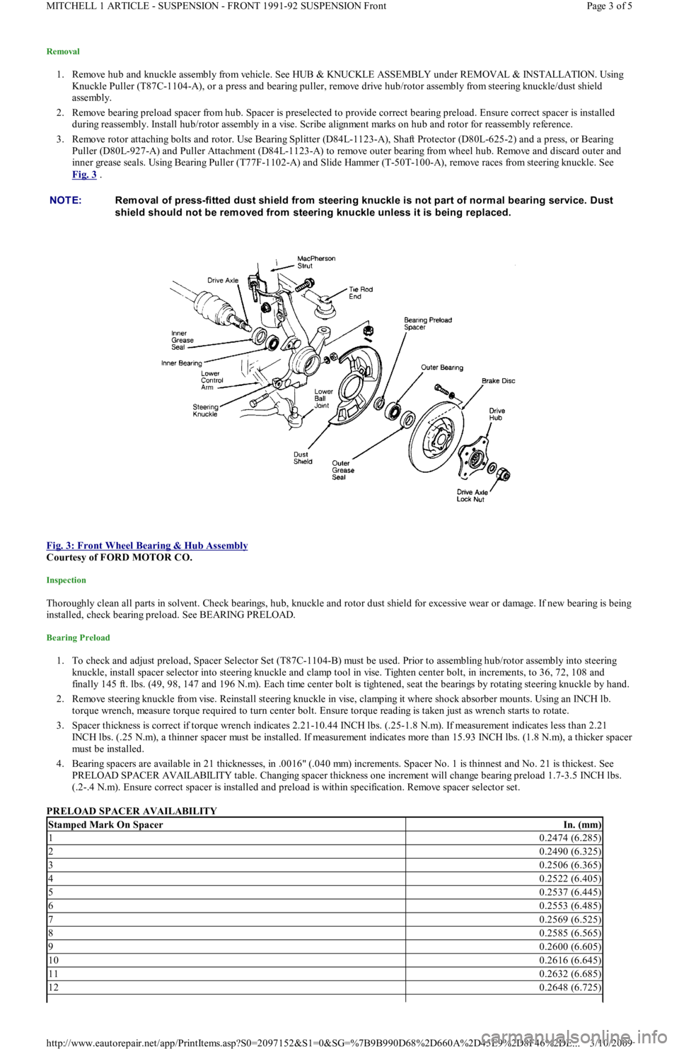
Fig. 3
.
Fig. 3: Front Wheel Bearing & Hub Assembly
Courtesy of FORD MOTOR CO.
Inspection
Thoroughly clean all parts in solvent. Check bearings, hub, knuckle and rotor dust shield for excessive wear or damage. If new bearing is being
installed, check bearing preload. See BEARING PRELOAD.
Bearing Preload
1. To check and adjust preload, Spacer Selector Set (T87C-1104-B) must be used. Prior to assembling hub/rotor assembly into steering
knuckle, install spacer selector into steering knuckle and clamp tool in vise. Tighten center bolt, in increments, to 36, 72, 108 and
finally 145 ft. lbs. (49, 98, 147 and 196 N.m). Each time center bolt is tightened, seat the bearings by rotating steering knuckle by hand.
2. Remove steering knuckle from vise. Reinstall steering knuckle in vise, clamping it where shock absorber mounts. Using an INCH lb.
torque wrench, measure torque required to turn center bolt. Ensure torque reading is taken just as wrench starts to rotate.
3. Spacer thickness is correct if torque wrench indicates 2.21-10.44 INCH lbs. (.25-1.8 N.m). If measurement indicates less than 2.21
INCH lbs. (.25 N.m), a thinner spacer must be installed. If measurement indicates more than 15.93 INCH lbs. (1.8 N.m), a thicker spacer
must be installed.
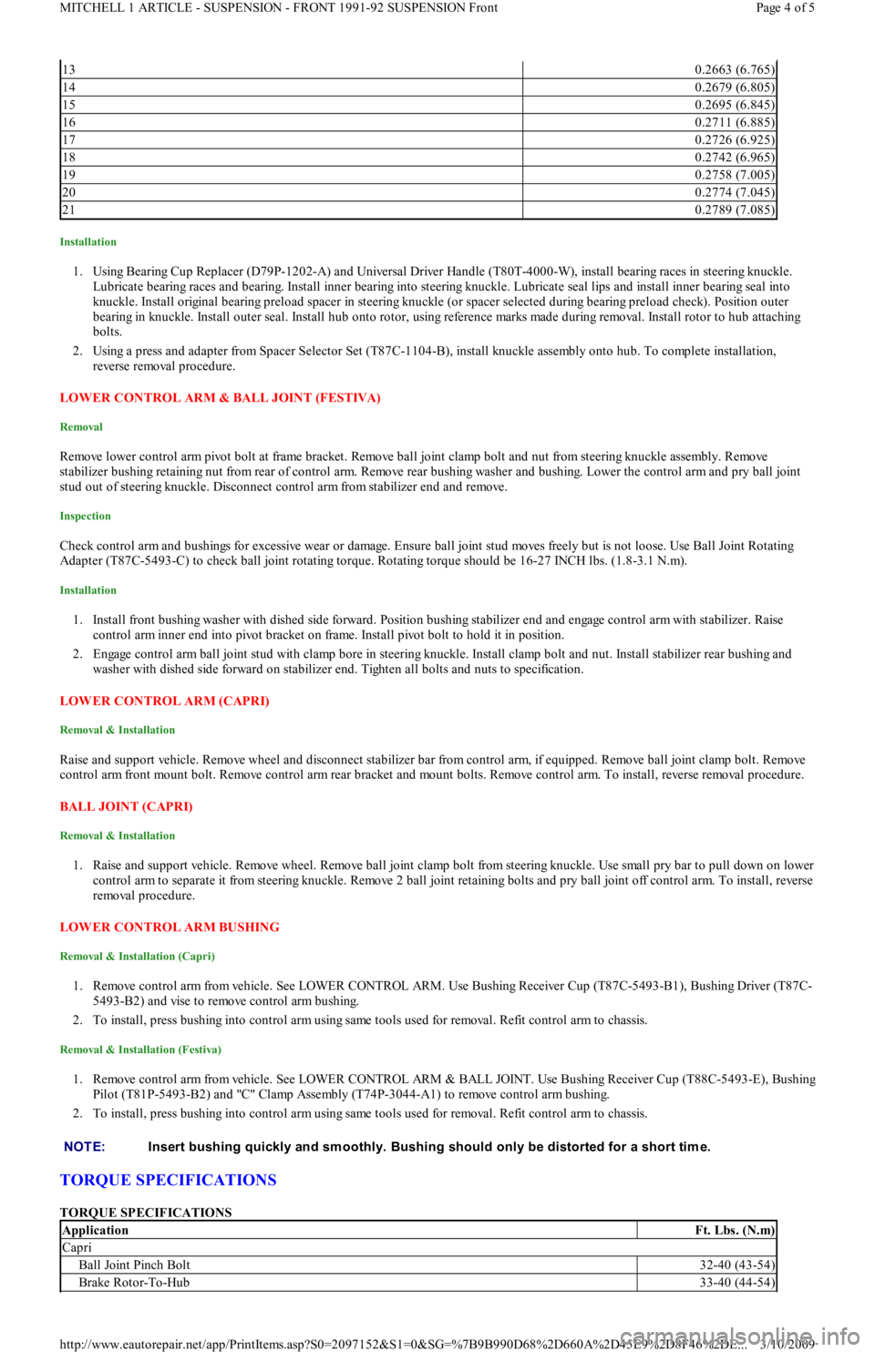
4. Bearing spacers are available in 21 thicknesses, in .0016" (.040 mm) increments. Spacer No. 1 is thinnest and No. 21 is thickest. See
PRELOAD SPACER AVAILABILITY table. Changing spacer thickness one increment will change bearing preload 1.7-3.5 INCH lbs.
(.2-.4 N.m). Ensure correct spacer is installed and preload is within specification. Remove spacer selector set.
PRELOAD SPACER AVAILABILITY NOTE:Rem oval of press-fitted dust shield from steering knuckle is not part of norm al bearing service. Dust
shield should not be rem oved from steering knuckle unless it is being replaced.
Stamped Mark On SpacerIn. (mm)
10.2474 (6.285)
20.2490 (6.325)
30.2506 (6.365)
40.2522 (6.405)
50.2537 (6.445)
60.2553 (6.485)
70.2569 (6.525)
80.2585 (6.565)
90.2600 (6.605)
100.2616 (6.645)
110.2632 (6.685)
120.2648 (6.725)
Page 3 of 5 MITCHELL 1 ARTICLE - SUSPENSION - FRONT 1991-92 SUSPENSION Front
3/10/2009 http://www.eautorepair.net/app/PrintItems.asp?S0=2097152&S1=0&SG=%7B9B990D68%2D660A%2D45E9%2D8F46%2DE
...
Page 394 of 454
Installation
1. Using Bearing Cup Replacer (D79P-1202-A) and Universal Driver Handle (T80T-4000-W), install bearing races in steering knuckle.
Lubricate bearing races and bearing. Install inner bearing into steering knuckle. Lubricate seal lips and install inner bearing seal into
knuckle. Install original bearing preload spacer in steering knuckle (or spacer selected during bearing preload check). Position outer
bearing in knuckle. Install outer seal. Install hub onto rotor, using reference marks made during removal. Install rotor to hub attaching
bolts.
2. Using a press and adapter from Spacer Selector Set (T87C-1104-B), install knuckle assembly onto hub. To complete installation,
reverse removal procedure.
LOWER CONTROL ARM & BALL JOINT (FESTIVA)
Removal
Remove lower control arm pivot bolt at frame bracket. Remove ball joint clamp bolt and nut from steering knuckle assembly. Remove
stabilizer bushing retaining nut from rear of control arm. Remove rear bushing washer and bushing. Lower the control arm and pry ball joint
stud out of steering knuckle. Disconnect control arm from stabilizer end and remove.
Inspection
Check control arm and bushings for excessive wear or damage. Ensure ball joint stud moves freely but is not loose. Use Ball Joint Rotating
Adapter (T87C-5493-C) to check ball joint rotating torque. Rotating torque should be 16-27 INCH lbs. (1.8-3.1 N.m).
Installation
1. Install front bushing washer with dished side forward. Position bushing stabilizer end and engage control arm with stabilizer. Raise
control arm inner end into pivot bracket on frame. Install pivot bolt to hold it in position.
2. Engage control arm ball joint stud with clamp bore in steering knuckle. Install clamp bolt and nut. Install stabilizer rear bushing and
washer with dished side forward on stabilizer end. Tighten all bolts and nuts to specification.
LOWER CONTROL ARM (CAPRI)
Removal & Installation
Raise and support vehicle. Remove wheel and disconnect stabilizer bar from control arm, if equipped. Remove ball joint clamp bolt. Remove
control arm front mount bolt. Remove control arm rear bracket and mount bolts. Remove control arm. To install, reverse removal procedure.
BALL JOINT (CAPRI)
Removal & Installation
1. Raise and support vehicle. Remove wheel. Remove ball joint clamp bolt from steering knuckle. Use small pry bar to pull down on lower
control arm to separate it from steering knuckle. Remove 2 ball joint retaining bolts and pry ball joint off control arm. To install, reverse
removal procedure.
LOWER CONTROL ARM BUSHING
Removal & Installation (Capri)
1. Remove control arm from vehicle. See LOWER CONTROL ARM. Use Bushing Receiver Cup (T87C-5493-B1), Bushing Driver (T87C-
5493-B2) and vise to remove control arm bushing.
2. To install, press bushing into control arm using same tools used for removal. Refit control arm to chassis.
Removal & Installation (Festiva)
1. Remove control arm from vehicle. See LOWER CONTROL ARM & BALL JOINT. Use Bushing Receiver Cup (T88C-5493-E), Bushing
Pilot (T81P-5493-B2) and "C" Clamp Assembly (T74P-3044-A1) to remove control arm bushing.
2. To install, press bushing into control arm using same tools used for removal. Refit control arm to chassis.
TORQUE SPECIFICATIONS
TORQUE SPECIFICATIONS
130.2663 (6.765)
140.2679 (6.805)
150.2695 (6.845)
160.2711 (6.885)
170.2726 (6.925)
180.2742 (6.965)
190.2758 (7.005)
200.2774 (7.045)
210.2789 (7.085)
NOTE:Insert bushing quickly and sm oothly. Bushing should only be distorted for a short tim e.
ApplicationFt. Lbs. (N.m)
Capri
Ball Joint Pinch Bolt32-40 (43-54)
Brake Rotor-To-Hub33-40 (44-54)
Page 4 of 5 MITCHELL 1 ARTICLE - SUSPENSION - FRONT 1991-92 SUSPENSION Front
3/10/2009 http://www.eautorepair.net/app/PrintItems.asp?S0=2097152&S1=0&SG=%7B9B990D68%2D660A%2D45E9%2D8F46%2DE
...
Page 401 of 454
and left brake lines in place. Install rear suspension struts and wheels. Block wheels and lower vehicle to load suspension to normal ride
height. Tighten torsion beam pivot bolts at body brackets to 69-87 ft. lbs. (93-118 N.m).
4. Check rear suspension alignment. Place an alignment mark at the center of the underbody, at a point of equal distance from the right and
left body bracket inboard mounting bolts. From this alignment mark, measure distance to centers of right and left strut lower mounting
bolts.
5. Both measurements must be within .20" (5 mm) of being the same. If not, shift torsion beam body brackets from side-to-side to center
suspension. Once centered, tighten upper body bracket mounting bolts to 40-50 ft. lbs. (54-68 N.m) and lower bolt to 69-87 ft. lbs. (93-
118 N.m). Bleed brakes.
TORSION BEAM BUSHINGS
Removal
1. Raise and support vehicle to fully extended rear struts. Remove wheels. Remove retaining clip at right brake line routing bracket and
disconnect brake line. Remove clip from left brake line and disconnect at body crossmember.
2. Remove torsion beam pivot bolt bolts and nuts at right and left body brackets. Swing torsion beam trailing arm downward to clear body
brackets.
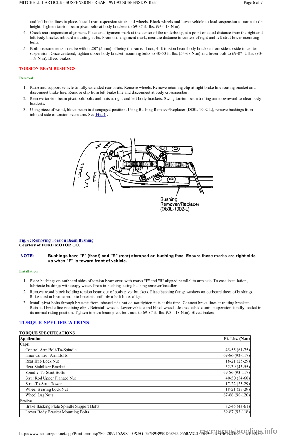
3. Using piece of wood, block beam in disengaged position. Using Bushing Remover/Replacer (D80L-1002-L), remove bushings from
inboard side of torsion beam arm. See Fig. 6
.
Fig. 6: Removing Torsion Beam Bushing
Courtesy of FORD MOTOR CO.
Installation
1. Place bushings on outboard sides of torsion beam arms with marks "F" and "R" aligned parallel to arm axis. To ease installation,
lubricate bushings with soapy water. Press in bushings using bushing remover/installer.
2. Remove wood block holding torsion beam out of body pivot brackets. Place bushing flange washers on outboard faces of bushings.
Raise torsion beam arms into brackets until pivot bolt holes align.
3. Install pivot bolts through brackets from inboard side but do not tighten nuts at this time. Connect brake lines at routing brackets.
Reinstall brake line retaining clips. Reinstall wheels. Lower vehicle and block wheels. Jounce vehicle until suspension is fully loaded in
its normal riding position. Tighten torsion beam pivot bolt nuts to 69-87 ft. lbs. (93-118 N.m). Bleed brakes.
TORQUE SPECIFICATIONS
TORQUE SPECIFICATIONS
NOTE:Bushings have "F" (front) and "R" (rear) stam ped on bushing face. Ensure these m arks are right side
up when "F" is toward front of vehicle.
ApplicationFt. Lbs. (N.m)
Capri
Control Arm Bolt-To-Spindle45-55 (61-75)
Inner Control Arm Bolts69-86 (93-117)
Rear Hub Lock Nut18-21 (25-29)
Rear Stabilizer Bracket32-39 (43-55)
Spindle-To-Strut Bolts69-86 (93-117)
Strut Rod Upper Flanged Nut40-50 (54-68)
Strut-To-Strut Tower17-22 (23-29)
Wheel Bearing Lock Nut18-21 (25-29)
Wheel Lug Nuts67-88 (90-120)
Festiva
Brake Backing Plate Spindle Support Bolts32-45 (43-61)
Lower Body Bracket Mounting Bolts69-87 (93-118)
Page 6 of 7 MITCHELL 1 ARTICLE - SUSPENSION - REAR 1991-92 SUSPENSION Rear
3/10/2009 http://www.eautorepair.net/app/PrintItems.asp?S0=2097152&S1=0&SG=%7B9B990D68%2D660A%2D45E9%2D8F46%2DE
...
Page 409 of 454
Back To Article
1988-94 AUT OMAT IC T RANSMISSIONS
Ford ATX Overhaul
APPLICATION
APPLICATION
DESCRIPTION
The transaxle consists of 3 main units: automatic transaxle, torque converter and differential assembly. The automatic transaxle consists of
front and rear clutches, one-way clutch, low-reverse brake assembly, oil pump and hydraulic controls (valve body and servo piston
assemblies). The valve body is controlled by the governor valve, vacuum throttle valve diaphragm (modulator) and kickdown solenoid. The
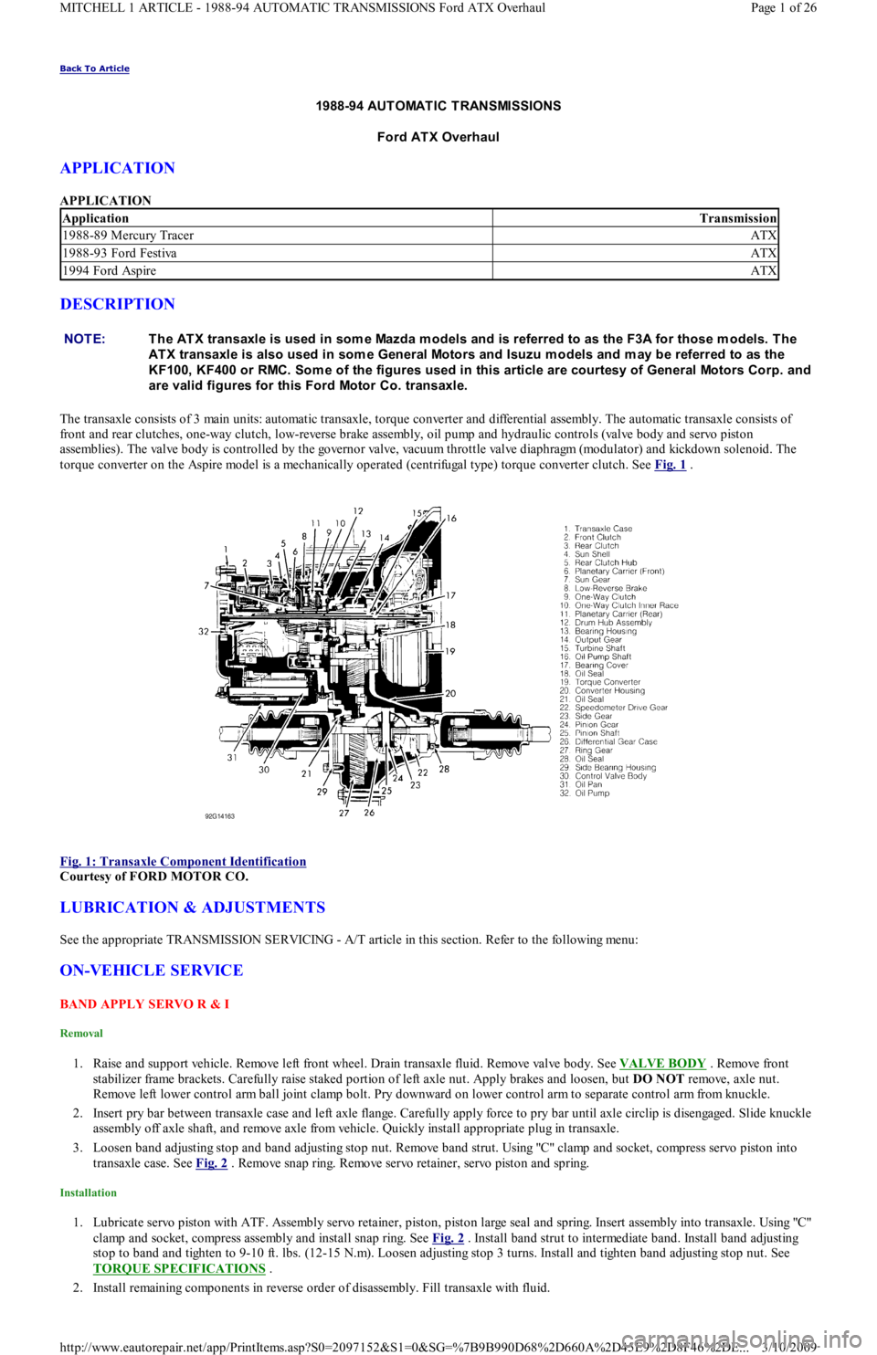
torque converter on the Aspire model is a mechanically operated (centrifugal type) torque converter clutch. See Fig. 1
.
Fig. 1: Transaxle Component Identification
Courtesy of FORD MOTOR CO.
LUBRICATION & ADJUSTMENTS
See the appropriate TRANSMISSION SERVICING - A/T article in this section. Refer to the following menu:
ON-VEHICLE SERVICE
BAND APPLY SERVO R & I
Removal
1. Raise and support vehicle. Remove left front wheel. Drain transaxle fluid. Remove valve body. See VALVE BODY . Remove front
stabilizer frame brackets. Carefully raise staked portion of left axle nut. Apply brakes and loosen, but DO NOT remove, axle nut.
Remove left lower control arm ball joint clamp bolt. Pry downward on lower control arm to separate control arm from knuckle.
2. Insert pry bar between transaxle case and left axle flange. Carefully apply force to pry bar until axle circlip is disengaged. Slide knuckle
assembly off axle shaft, and remove axle from vehicle. Quickly install appropriate plug in transaxle.
3. Loosen band adjusting stop and band adjusting stop nut. Remove band strut. Using "C" clamp and socket, compress servo piston into
transaxle case. See Fig. 2
. Remove snap ring. Remove servo retainer, servo piston and spring.
Installation
1. Lubricate servo piston with ATF. Assembly servo retainer, piston, piston large seal and spring. Insert assembly into transaxle. Usin g "C"
clamp and socket, compress assembly and install snap ring. See Fig. 2
. Install band strut to intermediate band. Install band adjusting
stop to band and tighten to 9-10 ft. lbs. (12-15 N.m). Loosen adjusting stop 3 turns. Install and tighten band adjusting stop nut. See
TORQUE SPECIFICATIONS
.
2. Install remaining components in reverse order of disassembly. Fill transaxle with fluid.
ApplicationTransmission
1988-89 Mercury TracerATX
1988-93 Ford FestivaATX
1994 Ford AspireATX
NOTE:T he AT X transaxle is used in som e Mazda m odels and is referred to as the F3A for those m odels. T he
AT X transaxle is also used in som e General Motors and Isuzu m odels and m ay be referred to as the
KF100, KF400 or RMC. Som e of the figures used in this article are courtesy of General Motors Corp. and
are valid figures for this Ford Motor Co. transaxle.
Page 1 of 26 MITCHELL 1 ARTICLE - 1988-94 AUTOMATIC TRANSMISSIONS Ford ATX Overhaul
3/10/2009 http://www.eautorepair.net/app/PrintItems.asp?S0=2097152&S1=0&SG=%7B9B990D68%2D660A%2D45E9%2D8F46%2DE
...
Page 435 of 454
Back To Article
T RANSMISSION REMOVAL & INST ALLAT ION - A/T
1988-93 T RANSMISSION SERVICING Ford Motor Co. T ransm ission Rem oval & Installation
TORQUE SPECIFICATIONS
TORQUE SPECIFICATIONS
ApplicationsFt. Lbs. (N.m)
Crossmember Attaching Bolt47-66 (64-89)
Engine-To-Transaxle Bolt41-59 (55-80)
Front Engine Mount-To-Crossmember Nut32-38 (43-52)
Front Wheel Lug Nuts65-87 (88-118)
Gusset Plate-To-Transaxle Bolt27-38 (37-52)
Left Stabilizer Body Bracket Nut/Bolt40-45 (54-61)
Lower Control Arm Clamp Nut/Bolt32-40 (43-54)
Manual Shift Lever Shaft Assembly Nut32-47 (44-64)
Rear Engine Mount-To-Crossmember Nut21-34 (28-46)
Stabilizer Bracket Mounting Nut40-45 (54-61)
Tie Rod End-To-Knuckle Nut26-30 (35-40)
Torque Converter Bolt25-36 (34-49)
INCH Lbs. (N.m)
Flywheel Cover Bolt62-89 (7-10)
Line Pressure Plug44-89 (5-10)
Shift Cable Retainer Bolts71-97 (8-11)
Copyr ight 2009 Mitchell Repair Information Company, LLC. All Rights Reserved.
Article GUID: A00124559
Page 1 of 1 MITCHELL 1 ARTICLE - TRANSMISSION REMOVAL & INSTALLATION - A/T 1988-93 TRANSMISSION SERVICING F
...
3/10/2009 http://www.eautorepair.net/app/PrintItems.asp?S0=2097152&S1=0&SG=%7B9B990D68%2D660A%2D45E9%2D8F46%2DE
...
Page 442 of 454
1. Check pressure plate surfaces for scoring, cracks or discoloration. Remove minor scratches or discoloration with fine emery cloth. Check
pressure plate diaphragm spring fingers for discoloration, scoring, broken or bent segments. Ensure all spring ends are the same height.
2. Check clutch disc lining surface for hardening or presence of oil. Check for worn clutch disc lining. Check for loose lining rivets.
Measure depth of rivet heads. Minimum allowable rivet depth is .012" (0.3 mm). Check for wear or rust on splines. Rust may be
removed with emery cloth.
3. Check flywheel surface for marks, scoring or discoloration. Minor surface repairs may be removed with fine emery cloth. Flywheel must
be machined if scoring, runout, or discoloration is excessive. Maximum flywheel runout is .008" (0.2 mm). Check for damaged or worn
ring gear teeth.
4. Check pilot bearing for wear. Check clutch release/throw out bearing for damage or wear at contact points. Rotate bearing in both
directions and check for binding or abnormal noise.
Installation
1. Replace release bearing and/or pilot bearing as necessary. Clean sealant from flywheel attaching bolt threads. Replace bolts if sealant
cannot be removed. Coat bolt threads with Stud/Bearing Mount Sealer (EOAZ-19554-B ), and install flywheel. Tighten bolts in a
diagonal sequence to specification. See TORQUE SPECIFICATIONS
at the end of this article.
2. Position clutch disc on flywheel with damper springs facing away from flywheel. Hold clutch disc in place with Clutch Aligner (T77F-
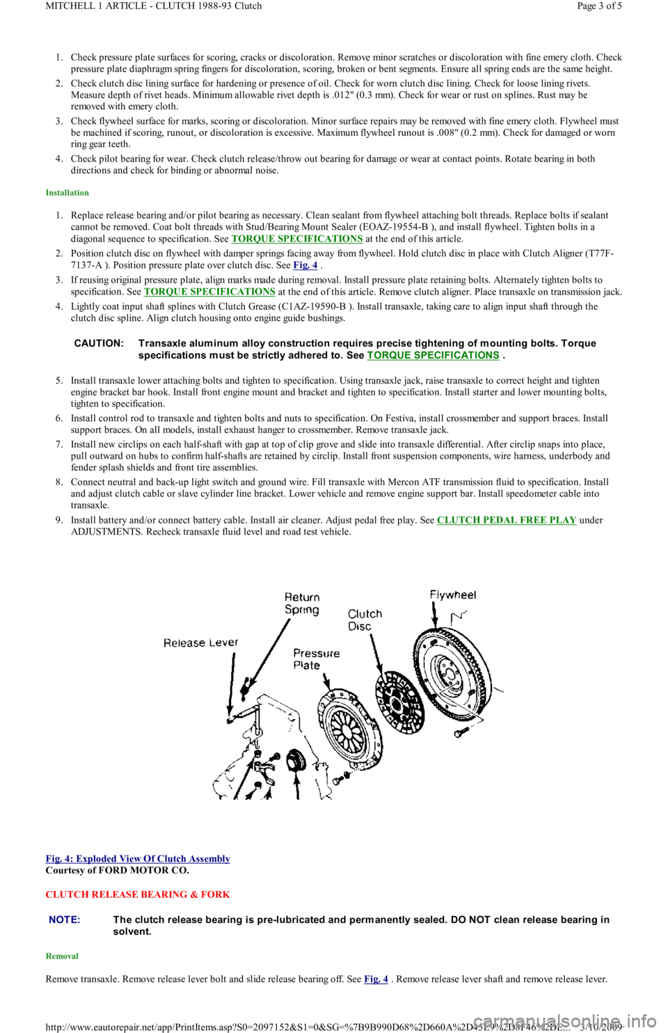
7137-A ). Position pressure plate over clutch disc. See Fig. 4
.
3. If reusing original pressure plate, align marks made during removal. Install pressure plate retaining bolts. Alternately tighten bolts to
specification. See TORQUE SPECIFICATIONS
at the end of this article. Remove clutch aligner. Place transaxle on transmission jack.
4. Lightly coat input shaft splines with Clutch Grease (C1AZ-19590-B ). Install transaxle, taking care to align input shaft through the
clutch disc spline. Align clutch housing onto engine guide bushings.
5. Install transaxle lower attaching bolts and tighten to specification. Using transaxle jack, raise transaxle to correct height and tighten
engine bracket bar hook. Install front engine mount and bracket and tighten to specification. Install starter and lower mounting b o l t s,
tighten to specification.
6. Install control rod to transaxle and tighten bolts and nuts to specification. On Festiva, install crossmember and support braces. Install
support braces. On all models, install exhaust hanger to crossmember. Remove transaxle jack.
7. Install new circlips on each half-shaft with gap at top of clip grove and slide into transaxle differential. After circlip snaps into place,
pull outward on hubs to confirm half-shafts are retained by circlip. Install front suspension components, wire harness, underbody and
fender splash shields and front tire assemblies.
8. Connect neutral and back-up light switch and ground wire. Fill transaxle with Mercon ATF transmission fluid to specification. In st al l
and adjust clutch cable or slave cylinder line bracket. Lower vehicle and remove engine support bar. Install speedometer cable into
transaxle.
9. Install battery and/or connect battery cable. Install air cleaner. Adjust pedal free play. See CLUTCH PEDAL FREE PLAY
under
ADJUSTMENTS. Recheck transaxle fluid level and road test vehicle.
Fig. 4: Exploded View Of Clutch Assembly
Courtesy of FORD MOTOR CO.
CLUTCH RELEASE BEARING & FORK
Removal
Remove transaxle. Remove release lever bolt and slide release bearing off. See Fig. 4 . Remove release lever shaft and remove release lever. CAUT ION: T ransaxle alum inum alloy construction requires precise tightening of m ounting bolts. T orque
specifications m ust be strictly adhered to. See T ORQUE SPECIFICAT IONS
.
NOTE:T he clutch release bearing is pre-lubricated and perm anently sealed. DO NOT clean release bearing in
solvent.
Page 3 of 5 MITCHELL 1 ARTICLE - CLUTCH 1988-93 Clutch
3/10/2009 http://www.eautorepair.net/app/PrintItems.asp?S0=2097152&S1=0&SG=%7B9B990D68%2D660A%2D45E9%2D8F46%2DE
...