Page 888 of 1640
Horns
Component Location Index
SRS components are located in this area. Review the
SRS component locations, precautions, and procedures
in the SRS section (24) before performing repairs or ser-
vice.
HORN RELAY
Test, page 23-249
UNDER-HOOD RELAY
BOX A
CABLE REEL
Test, page 23-250
HORN SWITCH
Test, page 23-249
Overhaul, section 17
SECURITY HORNTest, page 23-248
LEFT HORN
Test, page 23-248
RIGHT HORN
Test, page 23-248
SECURITY CONTROL
UNIT
Inpu
t
Test, page 23-320
('94-'96) ('93) ('91-'92)
UNDER-HOOD
FUSE/RELAY BOX
Description
Security Alarm System:
The security alarm system is an anti-theft alarm system. If someone tries to open the trunk, hood or either door without
the ignition key, or if the roof is not fully latched the security control unit senses a signal from the sensors and activates
relays to flash the headlights and sound the horn for about two minutes.ProCarManuals.com
Page 936 of 1640
Troubleshooting
Cruise Control
NOTE:
• The numbers in the table show the troubleshooting sequence.
• Before troubleshooting:
— Check the No. 5 (15 A) fuse in the under-dash fuse box, and the No. 29 (50 A) and No. 45 (20 A) fuses in the under-
hood fuse/relay box.
— Check that the horns sound.
— Make sure that the headlights go off.ProCarManuals.com
Page 948 of 1640

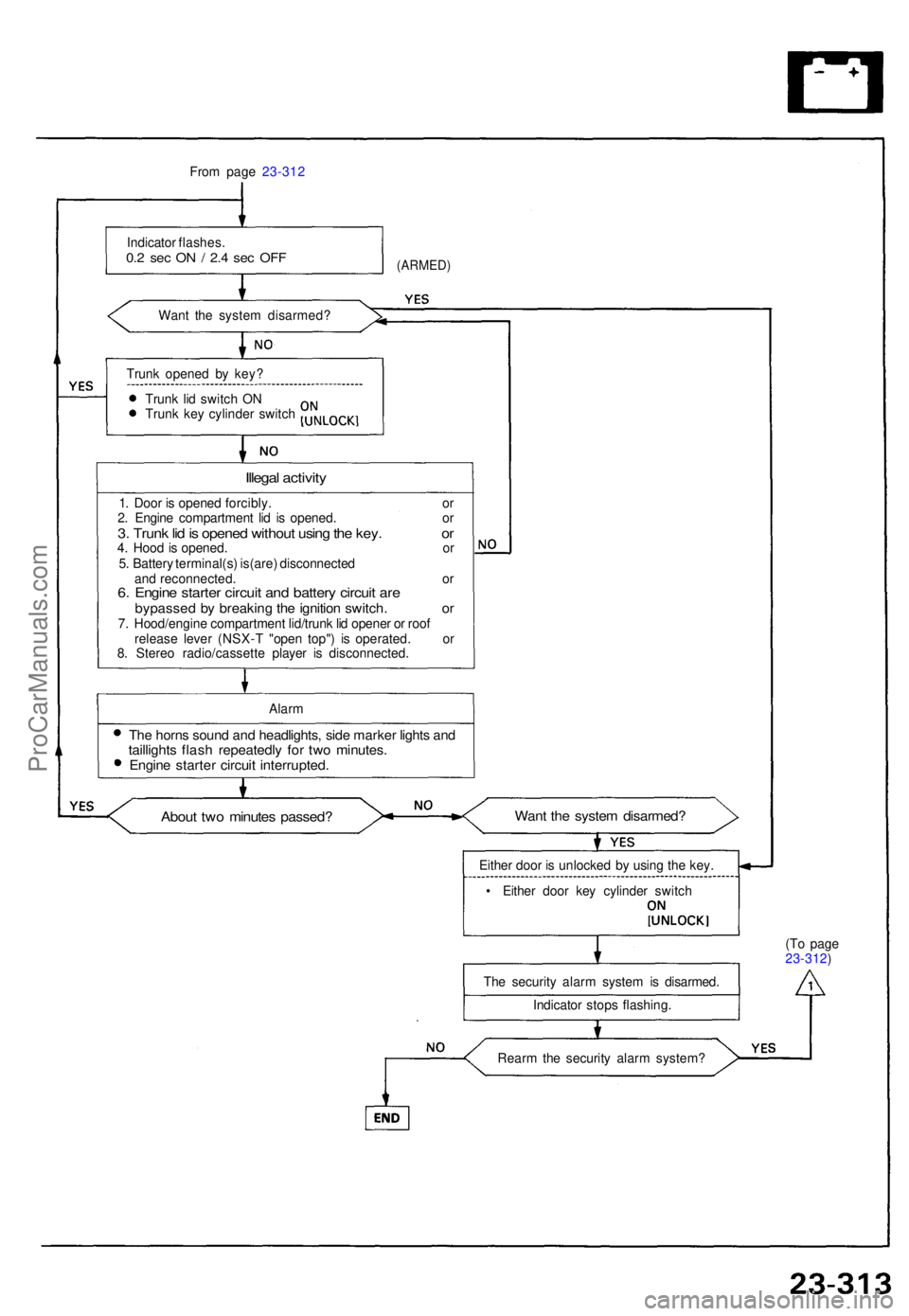
From pag e 23-31 2
Indicato r flashes .
0.2 se c O N / 2. 4 se c OF F
Wan t th e syste m disarmed ?
(ARMED)
Trunk opene d b y key ?
Trun k li d switc h O N
Trun k ke y cylinde r switc h
Illegal activit y
1. Doo r i s opene d forcibly . o r
2 . Engin e compartmen t li d i s opened . o r
3. Trun k li d is opene d withou t usin g th e key . o r4. Hoo d is opened . o r
5 . Batter y terminal(s ) is(are ) disconnecte d
an d reconnected . o r
6. Engin e starte r circui t an d batter y circui t ar ebypasse d b y breakin g th e ignitio n switch . o r7. Hood/engin e compartmen t lid/trun k li d opene r o r roo f
releas e leve r (NSX- T "ope n top" ) i s operated . o r
8 . Stere o radio/cassett e playe r i s disconnected .
Alar m
The horn s soun d an d headlights , sid e marke r light s an dtaillight s flas h repeatedl y fo r tw o minutes .Engine starte r circui t interrupted .
About tw o minute s passed ?Want th e syste m disarmed ?
Either doo r i s unlocke d b y usin g th e key .
• Eithe r doo r ke y cylinde r switc h
Th e securit y alar m syste m is disarmed .
Indicato r stop s flashing . (T
o pag e
23-312 )
Rear m th e securit y alar m system ?
ProCarManuals.com
Page 1097 of 1640
Idle Control System
Troubleshooting Flowchart
Alternator (ALT) FR Signal
This signals the ECM when the alternator is charging.
Inspection of ALT FR signal.
Connect the test harness be-
tween the ECM and connector.
Disconnect "D" connector from
the engine wire harness only, not
the ECM (see page 11-37).
Turn the ignition switch ON.
Measure voltage between D9 ( + ) terminal and A26 (-) ter-
minal.
Is there approx. 5 V?
Turn the ignition switch OFF.
Reconnect "D" connector to the
engine wire harness.
Warm up engine to normal oper-ating temperature (the cooling
fan comes on).
Measure voltage between D9( + ) terminal and A26 (-) ter-
minal.
Does the voltage decrease when
headlights and rear defogger are
turned on ?
Do the ECM Reset Procedure
(see page 11-35).
ALT FR signal is OK.(To page 11-93) Substitute a known-good ECM
and recheck. If prescribed
voltage is now available, replace
the original ECM.
Turn the ignition switch OFF.ProCarManuals.com
Page 1106 of 1640

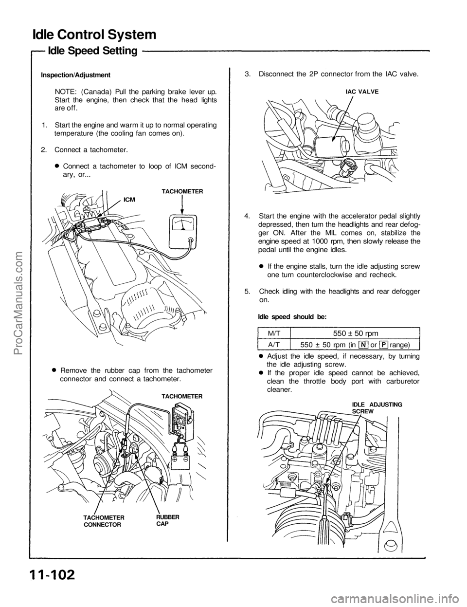
Idle Control System
Idle Speed Setting
Inspection/Adjustment NOTE: (Canada) Pull the parking brake lever up.
Start the engine, then check that the head lights
are
off.
1. Start the engine and warm it up to normal operating temperature (the cooling fan comes on).
2. Connect a tachometer. Connect a tachometer to loop of ICM second-
ary, or...
TACHOMETER
ICM
Remove the rubber cap from the tachometer
connector and connect a tachometer.
TACHOMETER
TACHOMETER CONNECTOR
RUBBER
CAP
3. Disconnect the 2P connector from the IAC valve.
IAC VALVE
4. Start the engine with the accelerator pedal slightly depressed, then turn the headlights and rear defog-
ger ON. After the MIL comes on, stabilize the
engine speed at 1000 rpm, then slowly release the
pedal until the engine idles.
If the engine stalls, turn the idle adjusting screw
one turn counterclockwise and recheck.
5. Check idling with the headlights and rear defogger
on.
Idle speed should be:
M/T
A/T
550 ± 50 rpm
550 ± 50 rpm (in or range)
Adjust the idle speed, if necessary, by turning
the idle adjusting screw.
If the proper idle speed cannot be achieved,
clean the throttle body port with carburetor
cleaner.
IDLE ADJUSTING
SCREWProCarManuals.com
Page 1107 of 1640
6. Turn the ignition switch OFF.
7. Reconnect the 2P connector on the IAC valve, then
remove CLOCK fuse in the under-hood fuse/relay
box for 10 seconds to reset ECM.
8. Restart and idle the engine with no-load conditions
in which the headlights, blower fan, rear defogger,
cooling fan, and air conditioner are not operating
for one minute, then check the idle speed.
Idle speed should be:
M/T
A/T
800
50 rpm
750
50 rpm
(in or range)ProCarManuals.com
Page 1138 of 1640

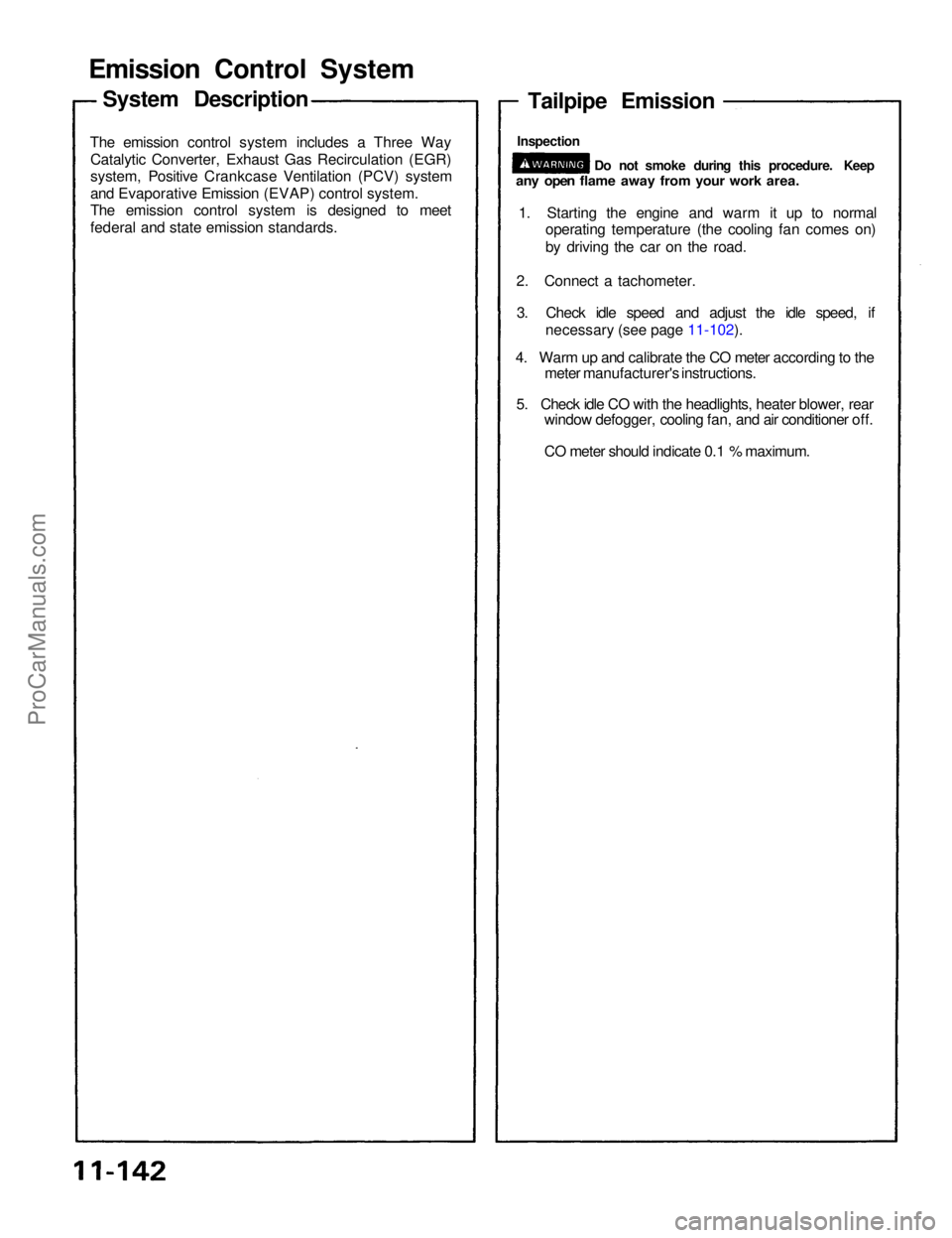
Emission Contro l Syste m
The emissio n contro l syste m include s a Thre e Wa y
Catalyti c Converter , Exhaus t Ga s Recirculatio n (EGR )
system , Positiv e Crankcas e Ventilatio n (PCV ) syste m
an d Evaporativ e Emissio n (EVAP ) contro l system .
Th e emissio n contro l syste m i s designe d t o mee t
federa l an d stat e emissio n standards .
Tailpipe Emissio n
1. Startin g th e engin e an d war m i t u p t o norma l
operatin g temperatur e (th e coolin g fa n come s on )
b y drivin g th e ca r o n th e road .
2 . Connec t a tachometer .
3 . Chec k idl e spee d an d adjus t th e idl e speed , i f
necessar y (se e pag e 11-102 ).
4 . War m up an d calibrat e th e C O mete r accordin g to th e
mete r manufacturer' s instructions .
5 . Chec k idl e C O wit h th e headlights , heate r blower , rea r
windo w defogger , coolin g fan , an d ai r conditione r off .
C O mete r shoul d indicat e 0. 1 % maximum .
System Descriptio n
Do no t smok e durin g thi s procedure . Kee pany ope n flam e awa y fro m you r wor k area .
Inspectio n
ProCarManuals.com
Page 1409 of 1640
UNDER HOOD FUSE/RELAY BOX
DIMME
R
RELAY
Test, page 23-189
UNDER-HOOD RELAY BOX A
TAILLKSHT RELAY
Test, page 23-190
HEADLIGHT RELAY
Test, page 23-189
RIGHT HEADLIGHT
RETRACTOR RELAY
Test, page 23-190
RIGHT HEADLIGHT
RETRACTOR MOTOR
Test, page 23-188
Replacement, page
23-186
RIGHT DAYTIME RUNNING
LIGHT (Canada)
Replacement, page
23-194
HEADLIGHTS
Ajustment, page 23-192
Replacement, page 23-193
LEFT DAYTIME RUNNING LIGHT (Canada)
Replacement
,
page 23-194
LEFT HEADLIGHT
RETRACTOR MOTOR
Test, page 23-188
Replacement, page 23-186 LEFT HEADLIGHT
RETRACTOR RELAY
Test
,
page 23-190
LEFT HEADLIGHT
RETRACTOR CUT RELAY
Test, page 23-190
RIGHT HEADLIGHT
RETRACTOR CUT RELAY
Test, page 23-190ProCarManuals.com