1990 VOLKSWAGEN CORRADO heater
[x] Cancel search: heaterPage 130 of 906

* ENGINE SYSTEMS UNIFORM INSPECTION GUIDELINES *
Article Text (p. 33)
1990 Volkswagen Corrado
For Volkswagen Technical Site: http://vw.belcom.ru
Copyright © 1998 Mitchell Repair Information Company, LLC
Thursday, March 23, 2000 09:32PM
³ hardware.
ÄÄÄÄÄÄÄÄÄÄÄÄÄÄÄÄÄÄÄÄÄÄÄÄÄÄÄÄÄÄÅÄÄÄÄÄÄÄÄÄÄÄÄÄÄÄÄÄÄÄÄÄÄÄÄÄÄÄÄÄÄÄÄÄÄÄÄÄÄÄLeaking
³ Require repair or replacement.
ÄÄÄÄÄÄÄÄÄÄÄÄÄÄÄÄÄÄÄÄÄÄÄÄÄÄÄÄÄÄÅÄÄÄÄÄÄÄÄÄÄÄÄÄÄÄÄÄÄÄÄÄÄÄÄÄÄÄÄÄÄÄÄÄÄÄÄÄÄÄContaminated
³ Require repair or replacement. Further
³ inspection required. See NOTE: below.
ÄÄÄÄÄÄÄÄÄÄÄÄÄÄÄÄÄÄÄÄÄÄÄÄÄÄÄÄÄÄÅÄÄÄÄÄÄÄÄÄÄÄÄÄÄÄÄÄÄÄÄÄÄÄÄÄÄÄÄÄÄÄÄÄÄÄÄÄÄÄImproper mechanical operation
³ Require repair or replacement.
ÄÄÄÄÄÄÄÄÄÄÄÄÄÄÄÄÄÄÄÄÄÄÄÄÄÄÄÄÄÄÁÄÄÄÄÄÄÄÄÄÄÄÄÄÄÄÄÄÄÄÄÄÄÄÄÄÄÄÄÄÄÄÄÄÄÄÄÄÄÄNOTE: Some components may be serviceable; check for accepted
cleaning procedure.
ÄÄÄÄÄÄÄÄÄÄÄÄÄÄÄÄÄÄÄÄÄÄÄÄÄÄÄÄÄÄÄÄÄÄÄÄÄÄÄÄÄÄÄÄÄÄÄÄÄÄÄÄÄÄÄÄÄÄÄÄÄÄÄÄÄÄÄÄÄÄEARLY FUEL EVAPORATION VALVE (HEAT RISER ASSEMBLY)
ÄÄÄÄÄÄÄÄÄÄÄÄÄÄÄÄÄÄÄÄÄÄÂÄÄÄÄÄÄÄÄÄÄÄÄÄÄÄÄÄÄÄÄÄÄÄÄÄÄÄÄÄÄÄÄÄÄÄÄÄÄÄÄÄÄÄÄÄÄÄCondition
³ Procedure
ÄÄÄÄÄÄÄÄÄÄÄÄÄÄÄÄÄÄÄÄÄÄÅÄÄÄÄÄÄÄÄÄÄÄÄÄÄÄÄÄÄÄÄÄÄÄÄÄÄÄÄÄÄÄÄÄÄÄÄÄÄÄÄÄÄÄÄÄÄÄInoperative, binding
³ Require repair or replacement.
ÄÄÄÄÄÄÄÄÄÄÄÄÄÄÄÄÄÄÄÄÄÄÅÄÄÄÄÄÄÄÄÄÄÄÄÄÄÄÄÄÄÄÄÄÄÄÄÄÄÄÄÄÄÄÄÄÄÄÄÄÄÄÄÄÄÄÄÄÄÄLeaking exhaust
³ Require repair or replacement.
ÄÄÄÄÄÄÄÄÄÄÄÄÄÄÄÄÄÄÄÄÄÄÅÄÄÄÄÄÄÄÄÄÄÄÄÄÄÄÄÄÄÄÄÄÄÄÄÄÄÄÄÄÄÄÄÄÄÄÄÄÄÄÄÄÄÄÄÄÄÄNoisy
³ Suggest repair or replacement.
ÄÄÄÄÄÄÄÄÄÄÄÄÄÄÄÄÄÄÄÄÄÄÁÄÄÄÄÄÄÄÄÄÄÄÄÄÄÄÄÄÄÄÄÄÄÄÄÄÄÄÄÄÄÄÄÄÄÄÄÄÄÄÄÄÄÄÄÄÄÄEARLY FUEL EVAPORATION, HEATER/GRID (EFE)
ÄÄÄÄÄÄÄÄÄÄÄÄÄÄÄÄÄÄÄÄÄÄÂÄÄÄÄÄÄÄÄÄÄÄÄÄÄÄÄÄÄÄÄÄÄÄÄÄÄÄÄÄÄÄÄÄÄÄÄÄÄÄÄÄÄÄÄÄÄÄCondition
³ Procedure
ÄÄÄÄÄÄÄÄÄÄÄÄÄÄÄÄÄÄÄÄÄÄÅÄÄÄÄÄÄÄÄÄÄÄÄÄÄÄÄÄÄÄÄÄÄÄÄÄÄÄÄÄÄÄÄÄÄÄÄÄÄÄÄÄÄÄÄÄÄÄInoperative
³ Require repair or replacement.
ÄÄÄÄÄÄÄÄÄÄÄÄÄÄÄÄÄÄÄÄÄÄÅÄÄÄÄÄÄÄÄÄÄÄÄÄÄÄÄÄÄÄÄÄÄÄÄÄÄÄÄÄÄÄÄÄÄÄÄÄÄÄÄÄÄÄÄÄÄÄRestricted
³ Require repair or replacement.
ÄÄÄÄÄÄÄÄÄÄÄÄÄÄÄÄÄÄÄÄÄÄÅÄÄÄÄÄÄÄÄÄÄÄÄÄÄÄÄÄÄÄÄÄÄÄÄÄÄÄÄÄÄÄÄÄÄÄÄÄÄÄÄÄÄÄÄÄÄÄDamaged
³ Suggest repair or replacement.
ÄÄÄÄÄÄÄÄÄÄÄÄÄÄÄÄÄÄÄÄÄÄÁÄÄÄÄÄÄÄÄÄÄÄÄÄÄÄÄÄÄÄÄÄÄÄÄÄÄÄÄÄÄÄÄÄÄÄÄÄÄÄÄÄÄÄÄÄÄÄ EXHAUST GAS RECIRCULATION SYSTEM (EGR)
EGR VALVE
ÄÄÄÄÄÄÄÄÄÄÄÄÄÄÄÄÄÄÄÄÄÄÂÄÄÄÄÄÄÄÄÄÄÄÄÄÄÄÄÄÄÄÄÄÄÄÄÄÄÄÄÄÄÄÄÄÄÄÄÄÄÄÄÄÄÄÄÄÄÄCondition
³ Procedure
ÄÄÄÄÄÄÄÄÄÄÄÄÄÄÄÄÄÄÄÄÄÄÅÄÄÄÄÄÄÄÄÄÄÄÄÄÄÄÄÄÄÄÄÄÄÄÄÄÄÄÄÄÄÄÄÄÄÄÄÄÄÄÄÄÄÄÄÄÄÄMissing
³ Require replacement.
ÄÄÄÄÄÄÄÄÄÄÄÄÄÄÄÄÄÄÄÄÄÄÅÄÄÄÄÄÄÄÄÄÄÄÄÄÄÄÄÄÄÄÄÄÄÄÄÄÄÄÄÄÄÄÄÄÄÄÄÄÄÄÄÄÄÄÄÄÄÄInoperative
³ Require repair or replacement.
ÄÄÄÄÄÄÄÄÄÄÄÄÄÄÄÄÄÄÄÄÄÄÅÄÄÄÄÄÄÄÄÄÄÄÄÄÄÄÄÄÄÄÄÄÄÄÄÄÄÄÄÄÄÄÄÄÄÄÄÄÄÄÄÄÄÄÄÄÄÄLeaking
³ Require repair or replacement.
ÄÄÄÄÄÄÄÄÄÄÄÄÄÄÄÄÄÄÄÄÄÄÅÄÄÄÄÄÄÄÄÄÄÄÄÄÄÄÄÄÄÄÄÄÄÄÄÄÄÄÄÄÄÄÄÄÄÄÄÄÄÄÄÄÄÄÄÄÄÄRestricted passage
³ Require repair or replacement.
ÄÄÄÄÄÄÄÄÄÄÄÄÄÄÄÄÄÄÄÄÄÄÅÄÄÄÄÄÄÄÄÄÄÄÄÄÄÄÄÄÄÄÄÄÄÄÄÄÄÄÄÄÄÄÄÄÄÄÄÄÄÄÄÄÄÄÄÄÄÄDamaged
³ Suggest repair or replacement.
ÄÄÄÄÄÄÄÄÄÄÄÄÄÄÄÄÄÄÄÄÄÄÅÄÄÄÄÄÄÄÄÄÄÄÄÄÄÄÄÄÄÄÄÄÄÄÄÄÄÄÄÄÄÄÄÄÄÄÄÄÄÄÄÄÄÄÄÄÄÄMaintenance interval
³ Suggest repair or replacement to comply with
Page 287 of 906

* SYMPTOM CHECK LIST *
Article Text (p. 10)
1990 Volkswagen Corrado
For Volkswagen Technical Site: http://vw.belcom.ru
Copyright © 1998 Mitchell Repair Information Company, LLC
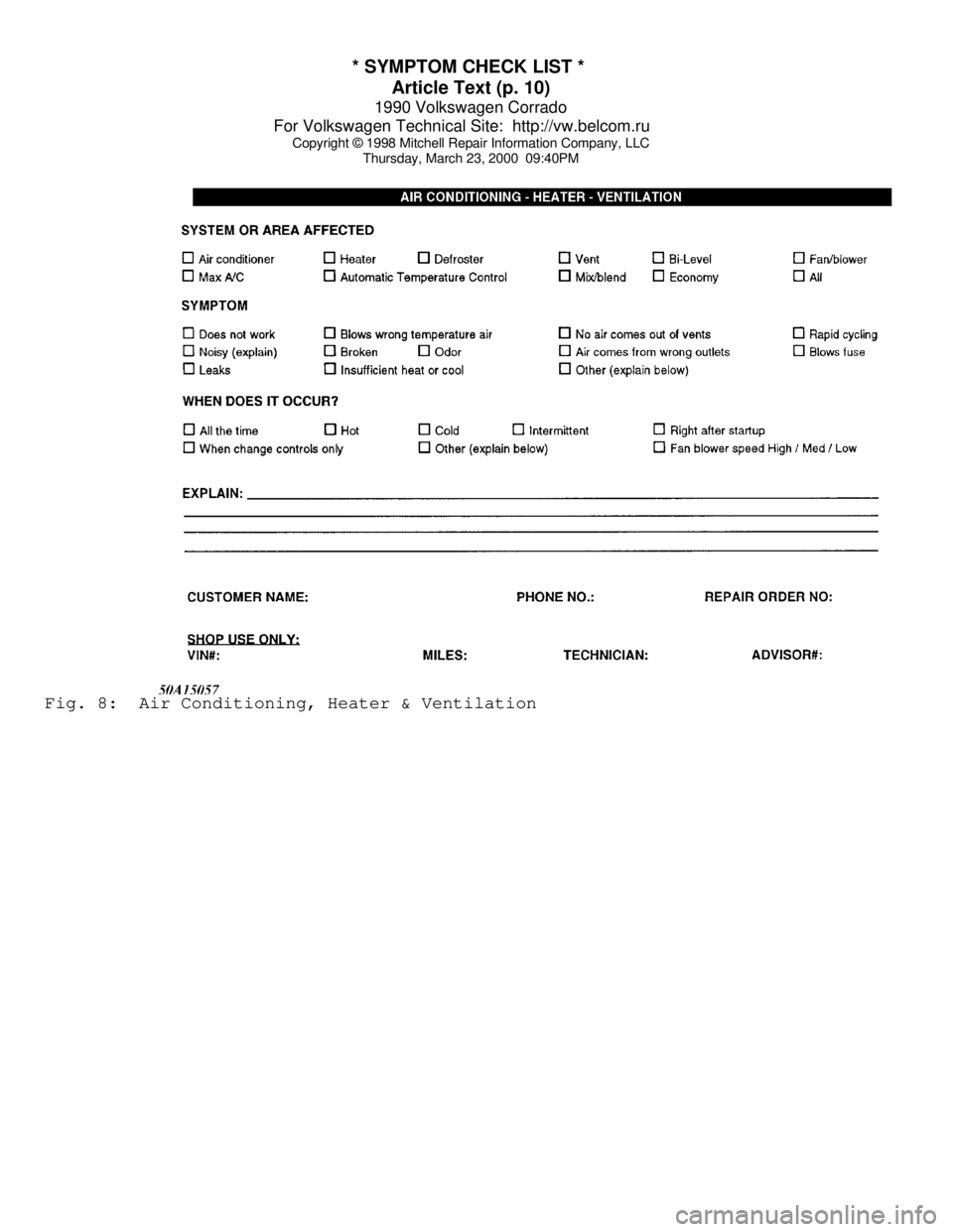
Thursday, March 23, 2000 09:40PMFig. 8: Air Conditioning, Heater & Ventilation
Page 293 of 906

1.8L 4-CYL 8-VALVE & 1.8L 4-CYL 16-VALVE
Article Text (p. 2)
1990 Volkswagen Corrado
For Volkswagen Technical Site: http://vw.belcom.ru
Copyright © 1998 Mitchell Repair Information Company, LLC
Thursday, March 23, 2000 09:40PM
NOTE: Match mark engine mounts to ensure original alignment is
achieved after installation. On vehicles with A/C and power
steering, remove components with hoses attached and secure
out of way.
ENGINE R & I (EXCEPT FOX)
REMOVAL (EXCEPT FOX)
1) Disconnect and remove battery. Open fuel tank fill cap and
radiator cap. Remove intake air duct. On 16-valve engines, remove
intake manifold assembly. On vehicles with A/C, remove trim panel and
lower apron. Remove condenser from crossmember and radiator. Remove
all duct work. Mark and disconnect A/C and cooling fan electrical
connectors. Remove accessory belts.
2) On Golf, GTI and Jetta models, leave A/C hoses attached
and remove A/C compressor. Pivot A/C condenser and compressor to side
of vehicle and secure.
3) On Cabriolet and Scirocco models, remove alternator and
timing belt cover. Remove 3 A/C bracket Allen head bolts behind timing
belt cover. Remove A/C bracket support brace. Remove A/C compressor
bracket bolts. Leave hoses attached and secure A/C compressor with
bracket out of way.
4) On all models, open heater controls. Remove cooling hose
from thermostat housing flange and drain coolant. Remove flange. Mark
and remove all cooling system hoses (as necessary).
5) On Golf, GTI and Jetta models, remove grille from radiator
support. Disconnect electrical connectors at radiator support. Remove
radiator-to-support bolts. Remove radiator support using care not
damage headlights. Remove radiator, fan and shroud assembly.
6) On all models, remove axle shafts from transaxle. See FWD
AXLE SHAFTS article in the DRIVE AXLES section. Mark and disconnect
shift linkage and speedometer cable. Mark and remove electrical
connectors and vacuum hoses (as necessary). Disconnect throttle,
cruise and kickdown cables (if equipped). Leave fuel lines connected
and remove cold start injector and warm-up regulator.
7) Remove fuel injectors and install protective caps and
plugs. Remove rear engine mount. Remove complete transaxle mount. On
Cabriolet models, remove right front tire assembly. Remove right and
left engine mount through bolts.
8) On all models, install engine sling on engine lift hooks.
Carefully raise engine and transaxle out of vehicle. Separate
transaxle from engine (if necessary).
INSTALLATION
1) To install, reverse removal procedure. Engine alignment
adjustment is necessary whenever engine is removed or mounts are
loosened. To adjust, loosen through bolt on engine mount "A". Loosen
transmission transaxle mount "B" bolts. Loosen front engine mount and
bracket. See Fig. 2.
2) Lightly rock engine and transaxle to allow position to
Page 294 of 906

1.8L 4-CYL 8-VALVE & 1.8L 4-CYL 16-VALVE
Article Text (p. 3)
1990 Volkswagen Corrado
For Volkswagen Technical Site: http://vw.belcom.ru
Copyright © 1998 Mitchell Repair Information Company, LLC
Thursday, March 23, 2000 09:40PM
shift as necessary. Evenly tighten mount bolts in reverse order of
loosening. Fill fluids to proper level. Adjust clutch pedal (if
equipped). Tighten all bolts and nuts to specifications.
ENGINE R & I (FOX)
REMOVAL (FOX)
1) Disconnect negative battery cable. Open heater valve,
coolant expansion tank and drain radiator through lower radiator hose.
Mark and disconnect all heater hoses. Disconnect electric cooling fan
and thermo switch. Remove lower and side radiator mounting bolts.
Remove fan, shroud and radiator. Remove M/T clutch cable (if
equipped).
2) Mark and disconnect electrical wiring and vacuum hoses (as
necessary). Disconnect throttle, cruise and kickdown linkage (if
equipped). Remove fuel injectors and install protective caps and
plugs. Leave fuel lines attached and remove cold start valve. Remove
charcoal canister and set aside.
3) Remove 3 upper engine-to-transaxle bolts. Remove intake
air duct. Remove left and right engine mount nuts. Disconnect and
remove starter assembly. Remove 2 lower engine-to-transaxle bolts.
Remove transaxle inspection cover plate. Disconnect exhaust inlet pipe
support and separate inlet pipe from exhaust manifold.
4) Support transaxle. Attach engine sling to engine lifting
hooks. Raise engine/transaxle until engine clears engine mounts.
Ensure transaxle is supported. Remove remaining engine-to-transaxle
bolts. Lift and separate engine from vehicle without transaxle.
INSTALLATION
Lubricate transaxle main shaft splines and contact area
between clutch release bearing and clutch pressure plate with MoS2
grease. DO NOT lubricate guide sleeve for clutch release bearing. To
complete installation, reverse removal procedure. DO NOT reuse self-
locking nuts. Ensure engine mounts are installed to original location.
Tighten engine mounts and subframe bolts with engine running at idle.
Page 297 of 906

1.8L 4-CYL 8-VALVE & 1.8L 4-CYL 16-VALVE
Article Text (p. 6)
1990 Volkswagen Corrado
For Volkswagen Technical Site: http://vw.belcom.ru
Copyright © 1998 Mitchell Repair Information Company, LLC
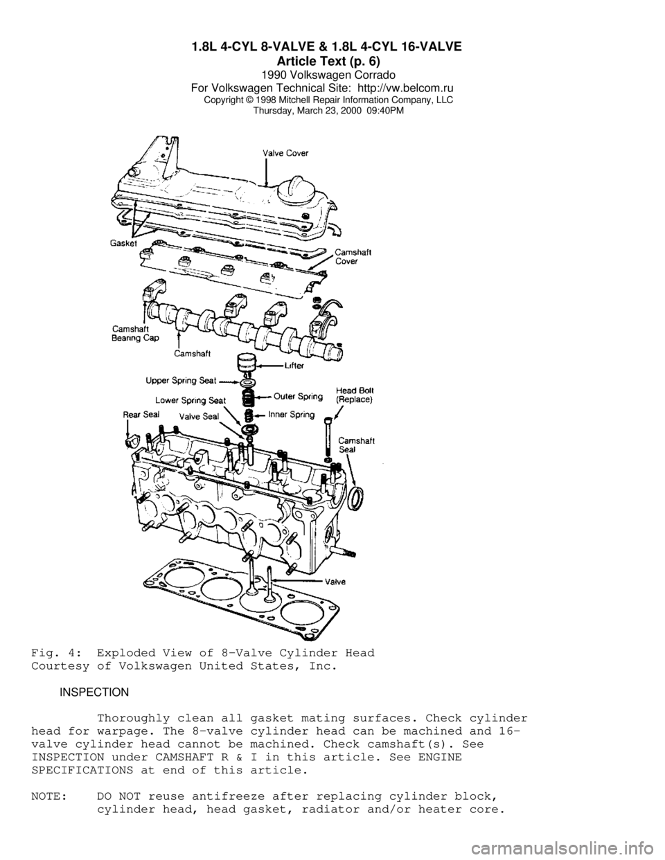
Thursday, March 23, 2000 09:40PMFig. 4: Exploded View of 8-Valve Cylinder Head
Courtesy of Volkswagen United States, Inc.
INSPECTION
Thoroughly clean all gasket mating surfaces. Check cylinder
head for warpage. The 8-valve cylinder head can be machined and 16-
valve cylinder head cannot be machined. Check camshaft(s). See
INSPECTION under CAMSHAFT R & I in this article. See ENGINE
SPECIFICATIONS at end of this article.
NOTE: DO NOT reuse antifreeze after replacing cylinder block,
cylinder head, head gasket, radiator and/or heater core.
Page 311 of 906

1.8L 4-CYL 8-VALVE & 1.8L 4-CYL 16-VALVE
Article Text (p. 20)
1990 Volkswagen Corrado
For Volkswagen Technical Site: http://vw.belcom.ru
Copyright © 1998 Mitchell Repair Information Company, LLC
Thursday, March 23, 2000 09:40PM
PRESSURE CAP
Pressure cap rating is 17-21 psi (1.2-1.5 kg/cmý).
COOLANT CAPACITY
ÄÄÄÄÄÄÄÄÄÄÄÄÄÄÄÄÄÄÄÄÄÄÄÄÄÄÄÄÄÄÄÄÄÄÄÄÄÄÄÄÄÄÄÄÄApplication Qts. (L)
Cabriolet ....................... 5.1 (4.8)
Fox ............................. 6.9 (6.5)
Golf & Golf GT .................. 7.3 (7.0)
Jetta ........................... 6.8 (6.5)
ÄÄÄÄÄÄÄÄÄÄÄÄÄÄÄÄÄÄÄÄÄÄÄÄÄÄÄÄÄÄÄÄÄÄÄÄÄÄÄÄÄÄÄÄÄ THERMOSTAT RATING
All engines use a 185
øF (94øC) rated thermostat.
WATER PUMP R & I
1) Disconnect negative battery cable. Turn heater control to
hot. Drain cooling system by disconnecting lower radiator hose at
thermostat housing. Remove accessories and brackets (as necessary).
2) Mark and remove coolant hoses from water pump. Remove
water pump pulley. Remove bolts and remove water pump assembly. To
install, reverse removal procedure. Remove thermo time switch, located
on water flange prior to filling cooling system.
TORQUE SPECIFICATIONS
TORQUE SPECIFICATIONS TABLE
ÄÄÄÄÄÄÄÄÄÄÄÄÄÄÄÄÄÄÄÄÄÄÄÄÄÄÄÄÄÄÄÄÄÄÄÄÄÄÄÄÄÄÄÄÄÄÄÄÄÄÄÄÄÄÄÄÄÄÄÄApplication Ft. Lbs. (N.m)
Camshaft Bearing Cap Nut
8-Valve ........................................ 15 (20)
16-Valve ....................................... 11 (15)
Camshaft Sprocket Bolt
8-Valve ........................................ 59 (80)
16-Valve ....................................... 48 (65)
Connecting Rod Cap Nut
1st Step ......................................... 22 (30)
2nd Step ................... Tighten Additional 90 Degrees
Crankshaft Pulley Nut ............................ 15 (20)
Crankshaft Sprocket Bolt
8-Valve .................................... (1) 66 (89)
16-Valve ..................................... 148 (200)
Cylinder Head Bolt (2)
Step 1 ......................................... 29 (39)
Step 2 ......................................... 44 (60)
Step 3 ............................................. (3)
Page 350 of 906

A/C SYSTEM GENERAL DIAGNOSTIC PROCEDURES
Article Text (p. 2)
1990 Volkswagen Corrado
For Volkswagen Technical Site: http://vw.belcom.ru
Copyright © 1998 Mitchell Repair Information Company, LLC
Thursday, March 23, 2000 09:41PM
5000 ........................ 24.92 ......................... +5.0
6000 ........................ 23.92 ......................... +6.0
7000 ........................ 23.02 ......................... +6.9
8000 ........................ 22.22 ......................... +7.7
9000 ........................ 21.32 ......................... +8.6
10,000 ...................... 20.52 ......................... +9.4
(1) - Add correction shown to gauge readings.ÄÄÄÄÄÄÄÄÄÄÄÄÄÄÄÄÄÄÄÄÄÄÄÄÄÄÄÄÄÄÄÄÄÄÄÄÄÄÄÄÄÄÄÄÄÄÄÄÄÄÄÄÄÄÄÄÄÄÄÄÄÄÄÄÄÄÄÄÄÄ PREPARATION FOR TESTING
1) Attach Low and High pressure gauges.
2) Start engine and allow to warm up.
3) Set system to "COOL" and blower to "HIGH".
4) Open car doors and hood.
5) Run engine at fast idle for 2-3 minutes.
AIR CONDITIONING SYSTEM PERFORMANCE CHECK TABLE
ÄÄÄÄÄÄÄÄÄÄÄÄÄÄÄÄÄÄÄÄÄÄÄÄÄÄÄÄÄÄÄÄÄÄÄÄÄÄÄÄÄÄÄÄÄÄÄÄÄÄÄÄÄÄÄÄÄÄÄÄÄÄÄÄÄÄÄÄÄPERFORM TESTS: SHOULD BE: IF:
ÄÄÄÄÄÄÄÄÄÄÄÄÄÄÄÄÄÄÄÄÄÄÄÄÄÄÄÄÄÄÄÄÄÄÄÄÄÄÄÄÄÄÄÄÄÄÄÄÄÄÄÄÄÄÄÄÄÄÄÄÄÄÄÄÄÄÄÄÄTemperature Check Temperature Check Is
* Switch to "LOW" blower.
* Close doors.
* Check outlet temperature. 35-45
ø F Too warm - Check control
lever operation, heater
water valve, cooling
system and gauge
readings.
ÄÄÄÄÄÄÄÄÄÄÄÄÄÄÄÄÄÄÄÄÄÄÄÄÄÄÄÄÄÄÄÄÄÄÄÄÄÄÄÄÄÄÄÄÄÄÄÄÄÄÄÄÄÄÄÄÄÄÄÄÄÄÄÄÄÄÄÄÄÄVisual Check Visual Check Shows:
* Compressor Quiet, No Leaks Noisy - Check belts, oil
level, seals, gaskets,
reed valves.
* Condenser Free of Obstructions Blocked - Clean off.
Plugged - Flush or
replace.
* Receiver-Drier Dry & warm to touch Frosty - Check for
restriction, replace
desiccant.
* Sight Glass Clear or few bubbles Bubbly, foamy or streaks
- Check gauge readings.
* High Side Lines Dry & warm to touch Frosty or very hot -
Check for restriction or
overcharge.
* Low Side Lines Dry & cool to touch Frosty or warm - Check
for restriction, low
charge or bad valve.
* Expansion Valve Dry Frosty - Check for
Page 358 of 906

A/C-HEATER SYSTEM - MANUAL
Article Text
1990 Volkswagen Corrado
For Volkswagen Technical Site: http://vw.belcom.ru
Copyright © 1998 Mitchell Repair Information Company, LLC
Thursday, March 23, 2000 09:41PM
ARTICLE BEGINNING
1990 MANUAL A/C-HEATER SYSTEMS
Volkswagen
Cabriolet, Corrado, Fox, Golf GL, GTI,
Jetta, Jetta GLi, Vanagon
* PLEASE READ THIS FIRST *
CAUTION: When discharging air conditioning system, use only approved
refrigerant recovery/recycling equipment. Make every attempt
to avoid discharging refrigerant into the atmosphere.
AIR BAG WARNING
WARNING: To avoid accidental air bag deployment on Cabriolet, see AIR
BAG DEACTIVATION under SERVICING PRECAUTIONS in this article.
DESCRIPTION
The Volkswagen air conditioning system is a cycling clutch
type. The compressor is cycled on and off by a thermostatic switch to
maintain constant cooling rate.
Other components include an evaporator, expansion valve,
receiver-drier, control panel, condenser, high-pressure switch and a
low-pressure switch. On Vanagon, the A/C thermostat can be found on
left rear pillar, above relay panel assembly (behind trim panel).
The control panel includes a pair of levers and a fan control
switch. The upper lever operates air distribution flap. The lower
lever controls temperature selection. The rotary fan control switch
controls fan speed selection.
OPERATION
SYSTEM CONTROLS
Air Distribution Lever
When in A/C position, cool air is routed to registers and
side air vents. In BI-LEVEL position, cool air is routed to floor
vents as well as registers and side air vents. In HEAT position, warm
air is routed to windshield vents, side window nozzles and floor and
center registers. In DEFOG position, warm air is routed to windshield
vents, side window nozzles and side registers.
Fan Control Knob
The fan control knob controls airflow. As knob is turned
clockwise, air intake opens and fan operates, increasing speed as knob
is moved to extreme right position.