Page 667 of 906
MIRRORS - POWER
Article Text
1990 Volkswagen Corrado
For Volkswagen Technical Site: http://vw.belcom.ru
Copyright © 1998 Mitchell Repair Information Company, LLC
Thursday, March 23, 2000 09:49PM
ARTICLE BEGINNING
1990-92 SAFETY EQUIPMENT
Power Mirrors
1990-92 Passat
1991-92 Corrado, Golf, GTI, Jetta, Vanagon
DESCRIPTION & OPERATION
Mirrors can be adjusted electrically from inside by operating
control knob on driver door panel. Adjustment control operates only
when ignition is on. To adjust driver-side or passenger-side mirror,
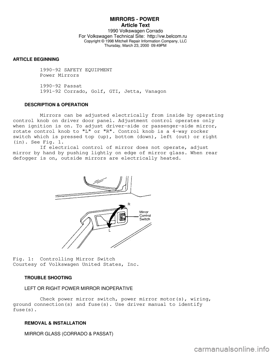
rotate control knob to "L" or "R". Control knob is a 4-way rocker
switch which is pressed top (up), bottom (down), left (out) or right
(in). See Fig. 1.
If electrical control of mirror does not operate, adjust
mirror by hand by pushing lightly on edge of mirror glass. When rear
defogger is on, outside mirrors are electrically heated.Fig. 1: Controlling Mirror Switch
Courtesy of Volkswagen United States, Inc.
TROUBLE SHOOTING
LEFT OR RIGHT POWER MIRROR INOPERATIVE
Check power mirror switch, power mirror motor(s), wiring,
ground connection(s) and fuse(s). Use driver manual to identify
fuse(s).
REMOVAL & INSTALLATION
MIRROR GLASS (CORRADO & PASSAT)
Page 726 of 906

SERVICE INDICATOR & WARNING LIGHTS
Article Text (p. 2)
1990 Volkswagen Corrado
For Volkswagen Technical Site: http://vw.belcom.ru
Copyright © 1998 Mitchell Repair Information Company, LLC
Thursday, March 23, 2000 09:51PM
started.
"BRAKE" INDICATOR LIGHT
Indicates the brake fluid level is low in the reservoir or
the parking brake is still on.
HIGH BEAM INDICATOR LIGHT
Light indicates that the head light high beam is on.
TURN SIGNAL INDICATOR LIGHTS
Indicate signal operation and direction.
SEAT BELT WARNING LIGHT
The warning light stays on until the driver's seat belt is
fastened.
ALTERNATOR WARNING LIGHT
Light comes on if alternator is not charging.
REAR WINDOW DEFOGGER INDICATOR
Indicates the rear defogger is on.
FOG LIGHTS INDICATOR
Indicates the fog lights are on.
EMERGENCY FLASHER INDICATOR
Indicates the emergency flashers are in operation.
"ECS" MALFUNCTION WARNING (IF EQUIPPED)
Warns of a malfunction in the emission control system.
OIL PRESSURE WARNING LIGHT
Indicates no, or low, oil pressure.
COOLANT TEMPERATURE & LEVEL WARNING (IF EQUIPPED)
Warns of excessive engine coolant temperature or low coolant
level in system.
"ABS" WARNING LIGHT
Warns of a malfunction in the anti-lock brake system.
Page 896 of 906

WIRING DIAGRAMS
Article Text
1990 Volkswagen Corrado
For Volkswagen Technical Site: http://vw.belcom.ru
Copyright © 1998 Mitchell Repair Information Company, LLC
Thursday, March 23, 2000 09:53PM
ARTICLE BEGINNING
1990 WIRING DIAGRAMS
Volkswagen
Corrado
COMPONENT LOCATION MENU
COMPONENT LOCATIONS TABLEÄÄÄÄÄÄÄÄÄÄÄÄÄÄÄÄÄÄÄÄÄÄÄÄÄÄÄÄÄÄÄÄÄÄÄÄÄÄÄÄÄÄÄÄÄÄÄÄÄÄÄÄÄÄÄÄÄÄÄÄComponent Figure No. (Location)
A/C COMP CLUTCH ................................. 4 (D 14)
A/C SYSTEM ................................. 4 (D-E 12-15)
ABS SYSTEM ................................... 2 (B-E 4-7)
ALTERNATOR ....................................... 1 (B 3)
AUTO SEAT BELTS ............................ 7 (B-E 25-27)
BACK-UP LIGHT SWITCH ............................ 6 (E 20)
BATTERY .......................................... 1 (A 2)
BEAM SELECT SWITCH .............................. 4 (A 12)
BRAKE & PARK BRAKE INDICATOR .................... 6 (A 22)
BRAKE FLUID LEVEL WARNING SWITCH ........ 2, 6 (E 6, A 23)
CASSETTE STORAGE LIGHT .......................... 6 (E 23)
CENTRAL LOCKS ................................ 8 (A 28-31)
CIG LIGHTER ..................................... 5 (A 16)
CRUISE CONTROL SYSTEM .......................... 2 (A 4-6)
DEFOG SWITCH .................................... 6 (E 21)
DIGIFANT CONTROL UNIT .......................... 1 (C-D 3)
DOOR SWITCHES ................................... 9 (E 35)
ECS-MALFUNCTION IND LIGHT & SWITCH ............... 3 (E 8)
EMERGENCY FLASHER SWITCH ..................... 4 (A 12-14)
FOG LIGHT ........................................ 1 (C 1)
FOG LIGHT SWITCH ................................ 4 (A 15)
FRESH AIR SWITCH ILLUM LIGHTS ................... 4 (D 12)
FUEL INJECTORS ................................. 1 (D-E 2)
FUEL PUMP AFTER RUN CONTROL UNIT ................ 3 (E 11)
FUEL TANK UNIT ................................ 3 (E 9-10)
FUS #23 ......................................... 4 (D 13)
FUSE/RELAY PANEL LAYOUT .................... 8 (D-E 29-31)
FUSE/RELAY PANEL ..................... 3, 4, 5, 6 (C 8-23)
GLOVE COMPT LIGHT ............................... 6 (D 23)
HEATED CRANKCASE BREATHER ....................... 3 (D 10)
HEATED SEATS ............................... 9 (C-E 32-34)
IGNITION COIL .................................... 1 (E 3)
IGNITION SWITCH .................................. 3 (A 8)
INSTRUMENT CLUSTER ......................... 7 (A-E 24-26)
INTERIOR LIGHT DELAY SWITCH ..................... 9 (E 33)
LEFT REAR MICRO SWITCH .......................... 7 (D 25)
LEFT SEAT BELT CONTROL UNIT ..................... 7 (D 27)
LIGHT SWITCH ................................. 3 (A 10-11)
LUGGAGE COMPT LIGHT ............................. 5 (A 17)