1990 VOLKSWAGEN CORRADO cruise control
[x] Cancel search: cruise controlPage 653 of 906

MAINTENANCE INFORMATION
Article Text (p. 18)
1990 Volkswagen Corrado
For Volkswagen Technical Site: http://vw.belcom.ru
Copyright © 1998 Mitchell Repair Information Company, LLC
Thursday, March 23, 2000 09:48PM
WARNING: Always disconnect battery ground cable before servicing
"high-current fuses. It is recommended that "high-current"
fuses be replaced by a qualified technician.
Fuse & Circuit Breaker Identification
1 - 10 Amp (Red)
Left Low Beam
2 - 10 Amp (Red)
Right Low Beam
3 - 10 Amp (Red)
Instrument Lights, License Plate Lights
4 - 15 Amp (Blue)
Rear Window Wiper, Sliding Roof
5 - 15 Amp (Blue)
Windshield & Rear Window Washer, Windshield Wiper
6 - 20 Amp (Yellow)
Air Conditioner, Fresh Air Fan
7 - 10 Amp (Red)
Right Tail & Side Lights
8 - 10 Amp (Red)
Left Tail & Side Lights
9 - 20 Amp (Yellow)
Rear Window Defroster, Mirror Heating
10 - 15 Amp (Blue)
Foglights
11 - 10 Amp (Red)
Left High Beam, High Beam Indicator
12 - 10 Amp (Red)
Right High Beam
13 - 10 Amp (Red)
Horn, Radiator Fan
14 - 15 Amp (Blue)
Back-Up Lights, Electric Mirrors, Heated Washer Jets
15 - 10 Amp (Red)
Crankcase Ventilation Heating Element
16 - 15 Amp (Blue)
Warning/Indicator Lights, Multi-Function Indicator, Glove Box
Light, Cassette Storage Light, Rear Spoiler Control Unit
17 - 10 Amp (Red)
Emergency Flashers, Turn Signals
18 - 20 Amp (Yellow)
Fuel Pump, Heated Oxygen Sensor Control
19 - 30 Amp (Green)
Radiator Fan, Air Conditioner
20 - 10 Amp (Red)
Brake Lights, Cruise Control
21 - 15 Amp (Blue)
Dome & Luggage Compartment Lights, Cigarette Lighter, Clock
Central Locking System, Multi-Function Indicator,
Rear Spoiler Adjustment
22 - 10 Amp (Red)
Page 655 of 906

MAINTENANCE INFORMATION
Article Text (p. 20)
1990 Volkswagen Corrado
For Volkswagen Technical Site: http://vw.belcom.ru
Copyright © 1998 Mitchell Repair Information Company, LLC
Thursday, March 23, 2000 09:48PM
WARNING: Always disconnect battery ground cable before servicing
"high-current fuses. It is recommended that "high-current"
fuses be replaced by a qualified technician.
Fuse & Circuit Breaker Identification
1 - 10 Amp (Red)
Left Low Beam
2 - 10 Amp (Red)
Right Low Beam
3 - 10 Amp (Red)
Instrument Lights, License Plate Lights
4 - 15 Amp (Blue)
Rear Window Wiper, Sliding Roof
5 - 15 Amp (Blue)
Windshield & Rear Window Washer, Windshield Wiper
6 - 20 Amp (Yellow)
Air Conditioner, Fresh Air Fan
7 - 10 Amp (Red)
Right Tail & Side Lights
8 - 10 Amp (Red)
Left Tail & Side Lights
9 - 20 Amp (Yellow)
Rear Window Defroster, Mirror Heating
10 - 15 Amp (Blue)
Foglights
11 - 10 Amp (Red)
Left High Beam, High Beam Indicator
12 - 10 Amp (Red)
Right High Beam
13 - 10 Amp (Red)
Horn, Radiator Fan
14 - 15 Amp (Blue)
Back-Up Lights, Electric Mirrors, Heated Washer Jets
15 - 10 Amp (Red)
Crankcase Ventilation Heating Element
16 - 15 Amp (Blue)
Warning/Indicator Lights, Multi-Function Indicator, Glove Box
Light, Cassette Storage Light, Rear Spoiler Control Unit
17 - 10 Amp (Red)
Emergency Flashers, Turn Signals
18 - 20 Amp (Yellow)
Fuel Pump, Heated Oxygen Sensor
19 - 30 Amp (Green)
Radiator Fan, Air Conditioner
20 - 10 Amp (Red)
Brake Lights, Cruise Control
21 - 15 Amp (Blue)
Dome & Luggage Compartment Lights, Cigarette Lighter, Clock
Central Locking System, Multi-Function Indicator,
Rear Spoiler Adjustment
22 - 10 Amp (Red)
Page 656 of 906

MAINTENANCE INFORMATION
Article Text (p. 21)
1990 Volkswagen Corrado
For Volkswagen Technical Site: http://vw.belcom.ru
Copyright © 1998 Mitchell Repair Information Company, LLC
Thursday, March 23, 2000 09:48PM
Radio
Relay & Circuit Breaker Identification
1 - A/C Control Module Relay
2 - Rear Window Wiper/Washer Relay
3 - ECM Power Supply Relay
4 - Load Reduction Relay
5 - Engine Coolant Level (ECL) Control Module
6 - Emergency Flasher Relay
7 - Headlight Washer Relay
8 - Washer/Wiper Intermittent Relay
9 - Seat Belt Warning Control Module
10 - Fog Lamp/Parking Lamp Relay
11 - Dual Horn Relay
12 - Fuel Pump Relay
13 - Back-Up Light Fuse (A/T)
14 - Coolant After-Run Control Module
15 - ABS Hydraulic Pump Relay
16 - ABS Relay
17 - Not Used
18 - Power Seat Fuse
19 - A/C Relay
20 - Park/Neutral Position (PNP) Relay
21 - ABS Hydraulic Pump Fuse/Power Window Circuit Breaker
22 - ABS Hydraulic Valve Fuse
23 - Cruise Control Fuse/Automatic Shoulder Belt System Fuse
24 - Not Used
END OF ARTICLE
Page 679 of 906

N - REMOVE/INSTALL/OVERHAUL
Article Text (p. 6)
1990 Volkswagen Corrado
For Volkswagen Technical Site: http://vw.belcom.ru
Copyright © 1998 Mitchell Repair Information Company, LLC
Thursday, March 23, 2000 09:49PM
sensor is free of contaminants, avoid using any cleaning solvents.
Sensor may be difficult to remove when engine temperature is less than
118øF (48øC). Always use anti-seize compound on threads before
installation. Tighten sensor to specification. See
TORQUE SPECIFICATIONS.
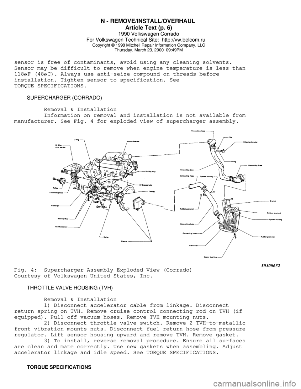
SUPERCHARGER (CORRADO)
Removal & Installation
Information on removal and installation is not available from
manufacturer. See Fig. 4 for exploded view of supercharger assembly.Fig. 4: Supercharger Assembly Exploded View (Corrado)
Courtesy of Volkswagen United States, Inc.
THROTTLE VALVE HOUSING (TVH)
Removal & Installation
1) Disconnect accelerator cable from linkage. Disconnect
return spring on TVH. Remove cruise control connecting rod on TVH (if
equipped). Pull off vacuum hoses. Remove TVH mounting nuts.
2) Disconnect throttle valve switch. Remove 2 TVH-to-metallic
front vibration mounts nuts. Disconnect fuel return hose from pressure
regulator. Lift sensor housing upward and remove TVH. Remove gasket.
3) To install, reverse removal procedure. Ensure all surfaces
are clean and mate correctly. Use new gaskets when assembling. Adjust
accelerator linkage and idle speed. See TORQUE SPECIFICATIONS.
TORQUE SPECIFICATIONS
Page 744 of 906

STEERING COLUMN SWITCHES
Article Text (p. 5)
1990 Volkswagen Corrado
For Volkswagen Technical Site: http://vw.belcom.ru
Copyright © 1998 Mitchell Repair Information Company, LLC
Thursday, March 23, 2000 09:51PM
Removal (Except Cabriolet)
1) Disconnect negative battery cable. Remove screws attaching
horn button assembly/center pad to steering wheel from behind steering
wheel (if equipped).
2) Pull horn button assembly/center pad from steering wheel.
Use a cloth covered screwdriver to pry off horn button assembly/center
pad (if necessary). Disassemble horn button assembly (if necessary).
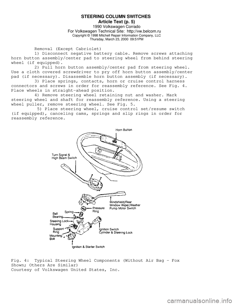
3) Place springs, contacts, horn or cruise control harness
connectors and screws in order for reassembly reference. See Fig. 4.
Place wheels in straight-ahead position.
4) Remove steering wheel retaining nut and washer. Mark
steering wheel and shaft for reassembly reference. Using a steering
wheel puller, remove steering wheel. See Fig. 5.
5) Place steering wheel, cruise control set/resume switch
(if equipped), canceling cams, springs and slip rings in order for
reassembly reference.Fig. 4: Typical Steering Wheel Components (Without Air Bag - Fox
Shown; Others Are Similar)
Courtesy of Volkswagen United States, Inc.
Page 896 of 906

WIRING DIAGRAMS
Article Text
1990 Volkswagen Corrado
For Volkswagen Technical Site: http://vw.belcom.ru
Copyright © 1998 Mitchell Repair Information Company, LLC
Thursday, March 23, 2000 09:53PM
ARTICLE BEGINNING
1990 WIRING DIAGRAMS
Volkswagen
Corrado
COMPONENT LOCATION MENU
COMPONENT LOCATIONS TABLEÄÄÄÄÄÄÄÄÄÄÄÄÄÄÄÄÄÄÄÄÄÄÄÄÄÄÄÄÄÄÄÄÄÄÄÄÄÄÄÄÄÄÄÄÄÄÄÄÄÄÄÄÄÄÄÄÄÄÄÄComponent Figure No. (Location)
A/C COMP CLUTCH ................................. 4 (D 14)
A/C SYSTEM ................................. 4 (D-E 12-15)
ABS SYSTEM ................................... 2 (B-E 4-7)
ALTERNATOR ....................................... 1 (B 3)
AUTO SEAT BELTS ............................ 7 (B-E 25-27)
BACK-UP LIGHT SWITCH ............................ 6 (E 20)
BATTERY .......................................... 1 (A 2)
BEAM SELECT SWITCH .............................. 4 (A 12)
BRAKE & PARK BRAKE INDICATOR .................... 6 (A 22)
BRAKE FLUID LEVEL WARNING SWITCH ........ 2, 6 (E 6, A 23)
CASSETTE STORAGE LIGHT .......................... 6 (E 23)
CENTRAL LOCKS ................................ 8 (A 28-31)
CIG LIGHTER ..................................... 5 (A 16)
CRUISE CONTROL SYSTEM .......................... 2 (A 4-6)
DEFOG SWITCH .................................... 6 (E 21)
DIGIFANT CONTROL UNIT .......................... 1 (C-D 3)
DOOR SWITCHES ................................... 9 (E 35)
ECS-MALFUNCTION IND LIGHT & SWITCH ............... 3 (E 8)
EMERGENCY FLASHER SWITCH ..................... 4 (A 12-14)
FOG LIGHT ........................................ 1 (C 1)
FOG LIGHT SWITCH ................................ 4 (A 15)
FRESH AIR SWITCH ILLUM LIGHTS ................... 4 (D 12)
FUEL INJECTORS ................................. 1 (D-E 2)
FUEL PUMP AFTER RUN CONTROL UNIT ................ 3 (E 11)
FUEL TANK UNIT ................................ 3 (E 9-10)
FUS #23 ......................................... 4 (D 13)
FUSE/RELAY PANEL LAYOUT .................... 8 (D-E 29-31)
FUSE/RELAY PANEL ..................... 3, 4, 5, 6 (C 8-23)
GLOVE COMPT LIGHT ............................... 6 (D 23)
HEATED CRANKCASE BREATHER ....................... 3 (D 10)
HEATED SEATS ............................... 9 (C-E 32-34)
IGNITION COIL .................................... 1 (E 3)
IGNITION SWITCH .................................. 3 (A 8)
INSTRUMENT CLUSTER ......................... 7 (A-E 24-26)
INTERIOR LIGHT DELAY SWITCH ..................... 9 (E 33)
LEFT REAR MICRO SWITCH .......................... 7 (D 25)
LEFT SEAT BELT CONTROL UNIT ..................... 7 (D 27)
LIGHT SWITCH ................................. 3 (A 10-11)
LUGGAGE COMPT LIGHT ............................. 5 (A 17)
Page 899 of 906

WIRING DIAGRAMS
Article Text (p. 4)
1990 Volkswagen Corrado
For Volkswagen Technical Site: http://vw.belcom.ru
Copyright © 1998 Mitchell Repair Information Company, LLC
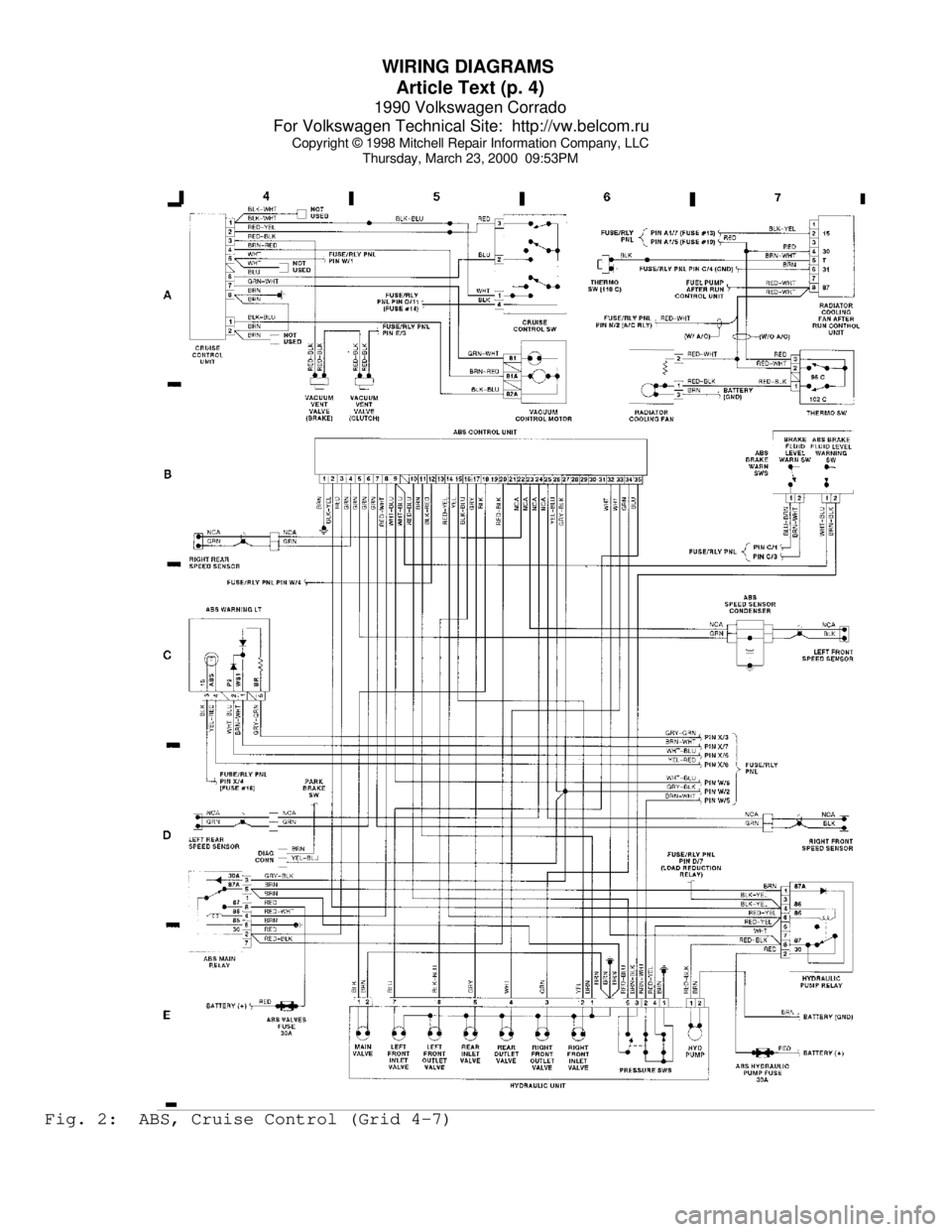
Thursday, March 23, 2000 09:53PMFig. 2: ABS, Cruise Control (Grid 4-7)