1990 VOLKSWAGEN CORRADO sensor
[x] Cancel search: sensorPage 655 of 906

MAINTENANCE INFORMATION
Article Text (p. 20)
1990 Volkswagen Corrado
For Volkswagen Technical Site: http://vw.belcom.ru
Copyright © 1998 Mitchell Repair Information Company, LLC
Thursday, March 23, 2000 09:48PM
WARNING: Always disconnect battery ground cable before servicing
"high-current fuses. It is recommended that "high-current"
fuses be replaced by a qualified technician.
Fuse & Circuit Breaker Identification
1 - 10 Amp (Red)
Left Low Beam
2 - 10 Amp (Red)
Right Low Beam
3 - 10 Amp (Red)
Instrument Lights, License Plate Lights
4 - 15 Amp (Blue)
Rear Window Wiper, Sliding Roof
5 - 15 Amp (Blue)
Windshield & Rear Window Washer, Windshield Wiper
6 - 20 Amp (Yellow)
Air Conditioner, Fresh Air Fan
7 - 10 Amp (Red)
Right Tail & Side Lights
8 - 10 Amp (Red)
Left Tail & Side Lights
9 - 20 Amp (Yellow)
Rear Window Defroster, Mirror Heating
10 - 15 Amp (Blue)
Foglights
11 - 10 Amp (Red)
Left High Beam, High Beam Indicator
12 - 10 Amp (Red)
Right High Beam
13 - 10 Amp (Red)
Horn, Radiator Fan
14 - 15 Amp (Blue)
Back-Up Lights, Electric Mirrors, Heated Washer Jets
15 - 10 Amp (Red)
Crankcase Ventilation Heating Element
16 - 15 Amp (Blue)
Warning/Indicator Lights, Multi-Function Indicator, Glove Box
Light, Cassette Storage Light, Rear Spoiler Control Unit
17 - 10 Amp (Red)
Emergency Flashers, Turn Signals
18 - 20 Amp (Yellow)
Fuel Pump, Heated Oxygen Sensor
19 - 30 Amp (Green)
Radiator Fan, Air Conditioner
20 - 10 Amp (Red)
Brake Lights, Cruise Control
21 - 15 Amp (Blue)
Dome & Luggage Compartment Lights, Cigarette Lighter, Clock
Central Locking System, Multi-Function Indicator,
Rear Spoiler Adjustment
22 - 10 Amp (Red)
Page 657 of 906

MAINTENANCE REMINDER LIGHT RESET PROCEDURES
Article Text
1990 Volkswagen Corrado
For Volkswagen Technical Site: http://vw.belcom.ru
Copyright © 1998 Mitchell Repair Information Company, LLC
Thursday, March 23, 2000 09:48PM
ARTICLE BEGINNING
1983-96 MAINTENANCE
Volkswagen Maintenance Reminder Light Reset Procedures
EGR MAINTENANCE LIGHT (IF EQUIPPED)
EGR light comes on at 15,000 mile intervals to indicate EGR
servicing is required. After checking EGR system, reset mileage
counter. See RESETTING MILEAGE COUNTER.
OXYGEN SENSOR WARNING LIGHT (IF EQUIPPED)
Oxygen sensor (OXS) light comes on at 30,000 mile intervals
to indicate oxygen sensor replacement. After installing new sensor,
reset mileage counter. See RESETTING MILEAGE COUNTER.
RESETTING MILEAGE COUNTER (IF EQUIPPED)
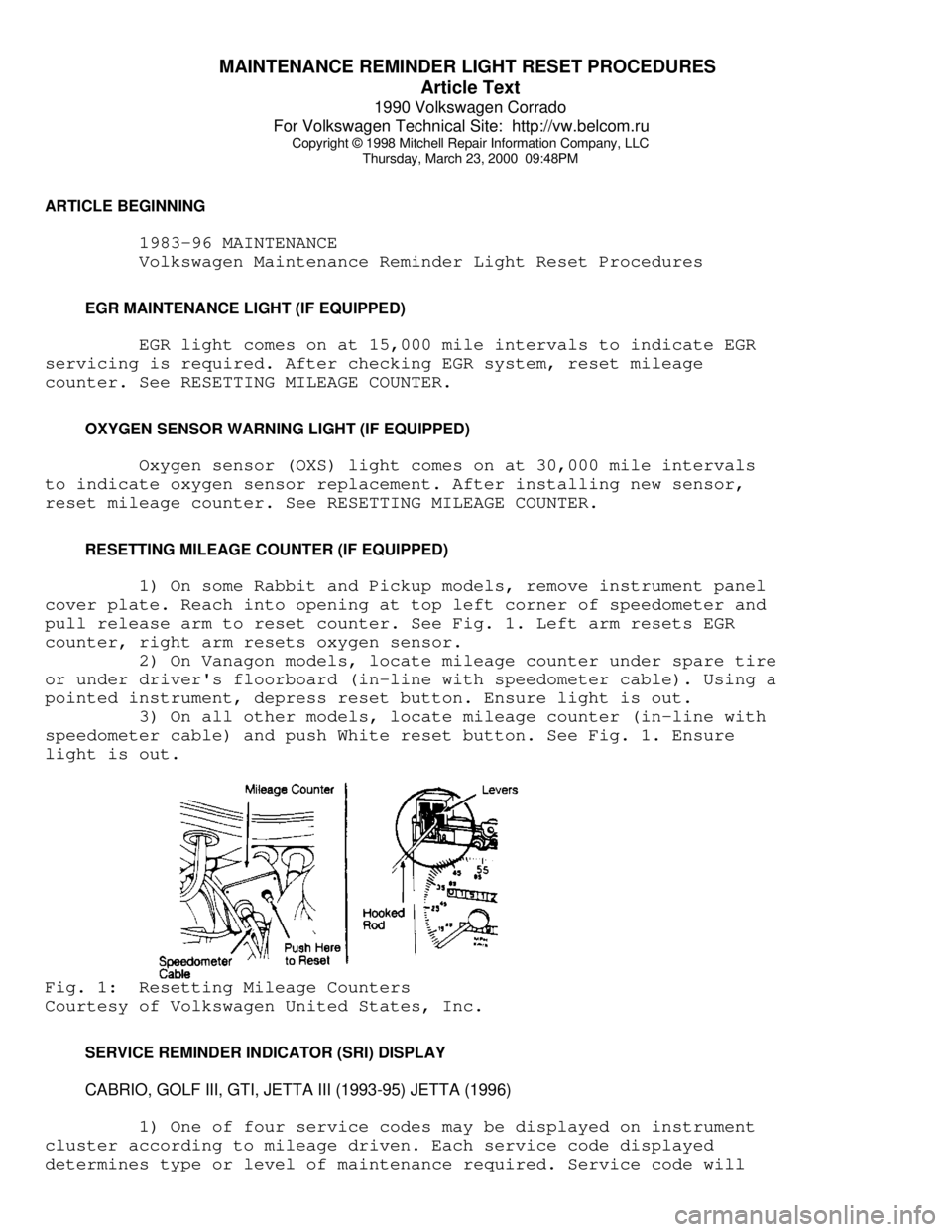
1) On some Rabbit and Pickup models, remove instrument panel
cover plate. Reach into opening at top left corner of speedometer and
pull release arm to reset counter. See Fig. 1. Left arm resets EGR
counter, right arm resets oxygen sensor.
2) On Vanagon models, locate mileage counter under spare tire
or under driver's floorboard (in-line with speedometer cable). Using a
pointed instrument, depress reset button. Ensure light is out.
3) On all other models, locate mileage counter (in-line with
speedometer cable) and push White reset button. See Fig. 1. Ensure
light is out.Fig. 1: Resetting Mileage Counters
Courtesy of Volkswagen United States, Inc.
SERVICE REMINDER INDICATOR (SRI) DISPLAY
CABRIO, GOLF III, GTI, JETTA III (1993-95) JETTA (1996)
1) One of four service codes may be displayed on instrument
cluster according to mileage driven. Each service code displayed
determines type or level of maintenance required. Service code will
Page 675 of 906

N - REMOVE/INSTALL/OVERHAUL
Article Text (p. 2)
1990 Volkswagen Corrado
For Volkswagen Technical Site: http://vw.belcom.ru
Copyright © 1998 Mitchell Repair Information Company, LLC
Thursday, March 23, 2000 09:49PM
distributor housing and install distributor hold-down clamp and bolt.
Install distributor cap. Check timing. Tighten hold-down bolt to
specification. See TORQUE SPECIFICATIONS.
AIRFLOW SENSOR PLATE
Removal & Installation
1) Remove air filter and unscrew stop bracket. Using heat
gun, heat locking compound on fastening bolt. Remove bolt slowly. DO
NOT damage threads. Clean locking compound from bolt hole threads.
2) Install airflow sensor plate. Ensure 5 dimple marks are
up. Lightly tighten self-locking screw. Ensure sensor plate is
centered and rest position is correct. To complete installation,
reverse removal procedure. See TORQUE SPECIFICATIONS.
AIRFLOW SENSOR POTENTIOMETER
Removal & Installation
Remove differential pressure regulator. Remove insulating
compound covering mounting screws. Remove potentiometer. DO NOT touch
or damage slide contact and conductor. To install, reverse removal
procedure. See TORQUE SPECIFICATIONS. Adjust potentiometer. See D -
ADJUSTMENTS article.
FUEL DISTRIBUTOR (1.8L ONLY)
CAUTION: Fuel system pressure must be relieved before removing or
disconnecting any fuel lines. Wipe up all spilled fuel
BEFORE continuing service.
Removal
1) Disconnect battery and remove air cleaner. Disconnect all
fuel and injector lines from fuel distributor. Plug fuel supply and
return lines. Catch any spilled fuel.
2) Disconnect wiring from differential pressure regulator.
Remove screws holding fuel distributor to airflow sensor housing.
Remove fuel distributor by turning back and forth while lifting up.
Air Sensor Plate Rest Position
Upper edge of sensor plate must be .070-080" (1.80-2.10 mm)
below lower edge of sensor cone. See Fig. 1. If rest position is
incorrect, raise sensor plate. Open or close wire clip to change
position of sensor plate. DO NOT bend leaf spring.Fig. 1: Identifying Sensor Plate Rest Position
Courtesy of Volkswagen United States, Inc.
Page 676 of 906

N - REMOVE/INSTALL/OVERHAUL
Article Text (p. 3)
1990 Volkswagen Corrado
For Volkswagen Technical Site: http://vw.belcom.ru
Copyright © 1998 Mitchell Repair Information Company, LLC
Thursday, March 23, 2000 09:49PM
Centering Sensor Plate & Lever
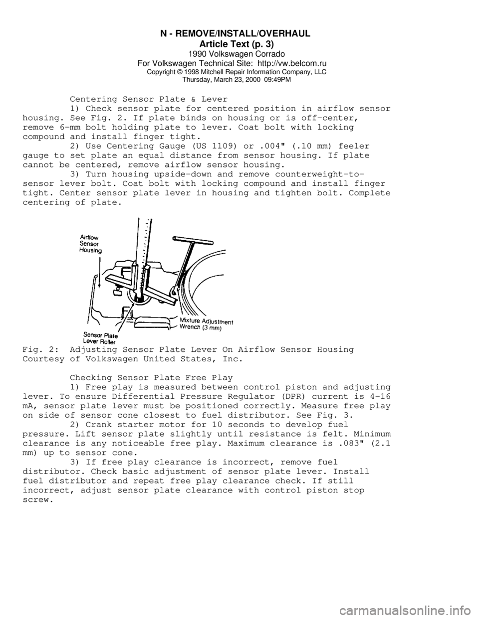
1) Check sensor plate for centered position in airflow sensor
housing. See Fig. 2. If plate binds on housing or is off-center,
remove 6-mm bolt holding plate to lever. Coat bolt with locking
compound and install finger tight.
2) Use Centering Gauge (US 1109) or .004" (.10 mm) feeler
gauge to set plate an equal distance from sensor housing. If plate
cannot be centered, remove airflow sensor housing.
3) Turn housing upside-down and remove counterweight-to-
sensor lever bolt. Coat bolt with locking compound and install finger
tight. Center sensor plate lever in housing and tighten bolt. Complete
centering of plate.Fig. 2: Adjusting Sensor Plate Lever On Airflow Sensor Housing
Courtesy of Volkswagen United States, Inc.
Checking Sensor Plate Free Play
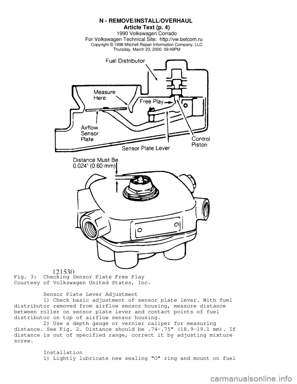
1) Free play is measured between control piston and adjusting
lever. To ensure Differential Pressure Regulator (DPR) current is 4-16
mA, sensor plate lever must be positioned correctly. Measure free play
on side of sensor cone closest to fuel distributor. See Fig. 3.
2) Crank starter motor for 10 seconds to develop fuel
pressure. Lift sensor plate slightly until resistance is felt. Minimum
clearance is any noticeable free play. Maximum clearance is .083" (2.1
mm) up to sensor cone.
3) If free play clearance is incorrect, remove fuel
distributor. Check basic adjustment of sensor plate lever. Install
fuel distributor and repeat free play clearance check. If still
incorrect, adjust sensor plate clearance with control piston stop
screw.
Page 677 of 906

N - REMOVE/INSTALL/OVERHAUL
Article Text (p. 4)
1990 Volkswagen Corrado
For Volkswagen Technical Site: http://vw.belcom.ru
Copyright © 1998 Mitchell Repair Information Company, LLC
Thursday, March 23, 2000 09:49PMFig. 3: Checking Sensor Plate Free Play
Courtesy of Volkswagen United States, Inc.
Sensor Plate Lever Adjustment
1) Check basic adjustment of sensor plate lever. With fuel
distributor removed from airflow sensor housing, measure distance
between roller on sensor plate lever and contact points of fuel
distributor on top of airflow sensor housing.
2) Use a depth gauge or vernier caliper for measuring
distance. See Fig. 2. Distance should be .74-.75" (18.9-19.1 mm). If
distance is out of specified range, correct it by adjusting mixture
screw.
Installation
1) Lightly lubricate new sealing "O" ring and mount on fuel
Page 678 of 906

N - REMOVE/INSTALL/OVERHAUL
Article Text (p. 5)
1990 Volkswagen Corrado
For Volkswagen Technical Site: http://vw.belcom.ru
Copyright © 1998 Mitchell Repair Information Company, LLC
Thursday, March 23, 2000 09:49PM
distributor. Install fuel distributor. See TORQUE SPECIFICATIONS for
tightening specifications. Connect all fuel lines except those to fuel
injectors. Check sensor plate adjusting lever and fuel distributor
control piston for smooth operation.
2) Remove fuel pump relay and bridge fuel pump circuit. Use
Jumper Switch (US 4480/3) in place of fuel pump relay. When pressure
has built up, turn off fuel pump. Move sensor plate from rest position
to end of travel.
3) Uniform resistance should be felt during entire movement.
No resistance should be felt during entire movement. No resistance
should be felt on quick return to rest position. Connect injector
lines. Install fuel pump relay. Start engine and check for leaks.
INJECTORS (DIGIFANT)
CAUTION: Fuel system pressure must be relieved before removing
injectors. Wipe up all spilled fuel BEFORE continuing
service.
Removal (AFC-Digifant II)
Disconnect negative battery cable. Disconnect main electrical
connector from fuel rail. Remove idle stabilizer valve. Loosen and
remove both hoses on each end of fuel rail. Remove fuel pressure
regulator and mounting bracket. Remove fuel rail mounting bolts. Pry
off injector mounting clips. Disconnect injector electrical
connectors. Remove fuel rail. Remove each injector from its insert.
Installation
To install injectors, reverse removal procedures. Use new "O"
rings when installing injectors. Replace hose clamps if necessary. See
TORQUE SPECIFICATIONS table at end of this article. Check for fuel
leaks.
INJECTORS (CIS SYSTEMS)
Removal (CIS-E & CIS-E Motronic)
Remove injectors from inserts in cylinder head with fuel
lines attached. Using 12-mm or 13-mm hex wrench, remove inserts from
head. Use 2 wrenches to remove injectors from fuel lines.
Installation
To install, reverse removal procedures. Use 2 wrenches when
tightening injector lines to injectors. Use new "O" rings lightly
lubricated. On models with 2-piece inserts, replace insert sealing
washer (against head) and use sealing compound on upper insert
threaded portion. See TORQUE SPECIFICATIONS.
OXYGEN (O2) SENSOR
Removal & Installation
Oxygen (O2) sensor is mounted in the exhaust pipe in front of
catalytic converter. Disconnect permanent pigtail from sensor. Ensure
Page 679 of 906

N - REMOVE/INSTALL/OVERHAUL
Article Text (p. 6)
1990 Volkswagen Corrado
For Volkswagen Technical Site: http://vw.belcom.ru
Copyright © 1998 Mitchell Repair Information Company, LLC
Thursday, March 23, 2000 09:49PM
sensor is free of contaminants, avoid using any cleaning solvents.
Sensor may be difficult to remove when engine temperature is less than
118øF (48øC). Always use anti-seize compound on threads before
installation. Tighten sensor to specification. See
TORQUE SPECIFICATIONS.
SUPERCHARGER (CORRADO)
Removal & Installation
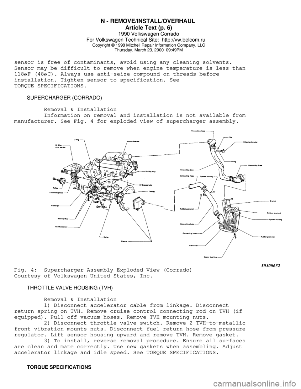
Information on removal and installation is not available from
manufacturer. See Fig. 4 for exploded view of supercharger assembly.Fig. 4: Supercharger Assembly Exploded View (Corrado)
Courtesy of Volkswagen United States, Inc.
THROTTLE VALVE HOUSING (TVH)
Removal & Installation
1) Disconnect accelerator cable from linkage. Disconnect
return spring on TVH. Remove cruise control connecting rod on TVH (if
equipped). Pull off vacuum hoses. Remove TVH mounting nuts.
2) Disconnect throttle valve switch. Remove 2 TVH-to-metallic
front vibration mounts nuts. Disconnect fuel return hose from pressure
regulator. Lift sensor housing upward and remove TVH. Remove gasket.
3) To install, reverse removal procedure. Ensure all surfaces
are clean and mate correctly. Use new gaskets when assembling. Adjust
accelerator linkage and idle speed. See TORQUE SPECIFICATIONS.
TORQUE SPECIFICATIONS
Page 680 of 906

N - REMOVE/INSTALL/OVERHAUL
Article Text (p. 7)
1990 Volkswagen Corrado
For Volkswagen Technical Site: http://vw.belcom.ru
Copyright © 1998 Mitchell Repair Information Company, LLC
Thursday, March 23, 2000 09:49PM
TORQUE SPECIFICATIONSÄÄÄÄÄÄÄÄÄÄÄÄÄÄÄÄÄÄÄÄÄÄÄÄÄÄÄÄÄÄÄÄÄÄÄÄÄÄÄÄÄÄÄÄÄÄÄÄÄÄÄÄÄÄÄÄÄÄÄÄÄÄÄÄÄÄÄÄÄÄApplication Ft. Lbs. (N.m)
AFC-Digifant II
Fuel Injector Inserts .................................... 15 (20)
Fuel Pressure Regulator Mounting Bolt .................... 11 (15)
Intercooler Bracket Mounting Bolts (Corrado) ............. 15 (20)
Knock Sensor ............................................. 15 (20)
Oxygen Sensor ............................................ 37 (50)
Supercharger Mounting Bolts (Corrado) .................... 18 (24)
Supercharger Pulley Bolt (Corrado) ....................... 33 (45)
Supercharger To Silencer Assembly Bolts (Corrado) ........ 18 (24)
Throttle Valve Body Mounting Bolts ....................... 15 (20)
CIS-E & CIS-E Motronic
Distributor Hold-Down Bolt (Fox) ......................... 18 (24)
Fuel Injection Valve Fuel Line Nut ....................... 18 (24)
Fuel Return Line Fitting ................................. 15 (20)
Fuel Supply Line Union Bolts ............................. 15 (20)
Intake Manifold Temperature Sensor (Jetta GLi 2.0L) ...... 15 (20)
Oxygen Sensor ............................................ 37 (50)
Thermo Time Switch (CIS-E) ............................... 22 (30)
Throttle Valve Housing Mounting Bolts .................... 15 (20)
INCH Lbs. (N.m)
AFC-Digifant II
Fuel Rail Mounting Bolts ................................. 87 (10)
Idle Stabilizer Valve Mounting Nuts ...................... 87 (10)
Intercooler Mounting Bolts (Corrado) ..................... 87 (10)
Supercharger Air Hose Mounting Bolts (Corrado) ........... 87 (10)
CIS-E & CIS-E Motronic
Auxiliary Air Regulator Mounting Bolts ................... 87 (10)
Cold Start Valve Mounting Bolts .......................... 87 (10)
Coolant Temperature Sensor ............................... 87 (10)
Distributor Hold-Down Bolt (Jetta GLi) ................... 87 (10)
EGR Valve Mounting Bolts ................................. 87 (10)
Fuel Distributor Mounting Bolts ......................... 30 (3.4)
Fuel Line Fittings ....................................... 87 (10)
Test Port Plug ........................................... 87 (10)
ÄÄÄÄÄÄÄÄÄÄÄÄÄÄÄÄÄÄÄÄÄÄÄÄÄÄÄÄÄÄÄÄÄÄÄÄÄÄÄÄÄÄÄÄÄÄÄÄÄÄÄÄÄÄÄÄÄÄÄÄÄÄÄÄÄÄÄÄÄÄEND OF ARTICLE