Page 205 of 391

17-12REAR SUSPENSION - Double Wishbone Suspension
12AWY
lZAOOS!
When cornering. I.to the right
I Toe-inToe angle
ReboundBump-
PositiveCamber(to body)
- Camber to ground: 0
Bump
Semi-trailing typeThis middle joint is located exterior to straight line
(p’connecting the trailing arm end mounted on the crossmet
ber side with the axle housing (king pin).
Because of this arrangement, the momentary center
P(intersection of front member centerline
(0,) of the trailing
arm and line
(02) interconnecting the middle points of the
lateral arm mounting points) is positioned rearward of the
wheel center.
3. When the wheel is subjected to an external force acting
towards the rear or to a braking reaction, the force FR acts
as a moment about momentary center
P, causing the tire to
steer in the toe-in direction, thereby securing directional
stability of the vehicle.
While the vehicle is cornering, side force Fc acts on the
outer wheel from the inside and side force Fc’ acts on the
inner wheel from the outside. These forces work
moments about momentary centers
P and P’, respective,,
to cause the outer wheel to be steered toward toe-in and
the inner wheel toward toe-out: As a result, both wheels
are steered in the same direction as the cornering direction
of the vehicle. This results in under-steering to improve
cornering performance and stability.
4.The change in toe angle and camber to ground is kept small
for bumps or rebounds as shown at the left and this
contributes to steering stability while cornering.
Page 206 of 391

-
REAR SUSPENSION -Double Wishbone Suspension17-13
Member supponbushingI
12AOO5
Upper arm
Link diagram of ordinarydouble wishbone suspension system
5. The suspension crossmember is mounted with the mem-
ber support bushing on the body. The input from the wheel
is first damped by the trailing arm and the bushings of the
lateral arms. It is then further damped by the member
support bushing. This dual anti-vibration construction
provides low vibration and low noise.
In addition, mounting of the differential carrier on this
crossmember decreases the natural frequency of the
crossmember, further damping vibrations.
The lower natural frequency of the crossmember allows
harder adjustment of the support bushing so that the
tendency toward oversteering of the suspension due to
side force, occurring during cornering can be reduced. This,
combined with understeering tendency by middle joint
.displacement described in (3) above, results in totally slight
understeering tendency.
Why this new rear suspension system is classified as a double
wishbone suspension
The new rear suspension is represented below by the diagram
as an aid to understanding its construction.
F-7-,12AOO33!A/ \
12AOO37Point A can rotate about rotary axis B-C and point
Dcan rotate about rotary axis E-C. The triangles ABC
and DEC can rotate like wishbone suspension
arms.When this is compared to an ordinary double
wishbone type suspension, it may be regarded asone with forward points
C, and C2 of the upper and
lower arms located at the same point. Thus, this
new rear suspension system is considered as a
double wishbone suspension system.
Page 212 of 391
POWER STEERING- General Information19-3
SPEClFlCATlONSItems
Steering wheel O.D.
mm (in.)Steering wheel maximum turns
Shaft and joint type
Steering angleInner wheel
Outer wheel
Tilt strokemm
(in.1Steering gear type
Rack strokemm (in.)Oil pump type
Oil pump displacement
cm3/rev. (cu.in./rev.)Specifications
372
(14.6)
2.7
Collapsible, cross joints (two joints used)
35”OO’ + 2”
29”20’
30
(1.2)
Rack and pinion
138
(5.41
Vane type9.6
l.59)
Page 215 of 391

19-6POWER STEERING- Pinion and Valve Assembly Construction
PINION AND VALVE ASSEMBLY
CONSTRUCTION
RISKAMThe pinion and valve assembly is composed of the
input shaft, torsion bar, pinion gear and rotary valve.torsion bar, the pinion gear is provided with a
stopper. Note that this stopper also functions to
The input shaft is hollow and incorporates the
fa&tate the transmission 6i the turning effort of
torsion bar within it; the upper end is secured bythe steering wheel directly to the pinion gear by
a pin to the torsion bar, and the lower end is heldthe input shaft in the event of a malfunction of
by the bushing within the pinion gear.the hydraulic system (such as breakage of the oil
The torsion bar is coupled to the pinion gear bypump’s V-belt, fluid leakage, etc.).
the serrated part at the lower end.
lThe rotary valve is attached to the pinion gear by
In order to prevent excessive torsion of thea dowel pin.
Torsion barPm13AOO76Dowel
Section A-A
Input shaft\Torsion barpin’Stopper
/Rotary valvePinion gear1310202
Page 216 of 391

:POWER STEERING
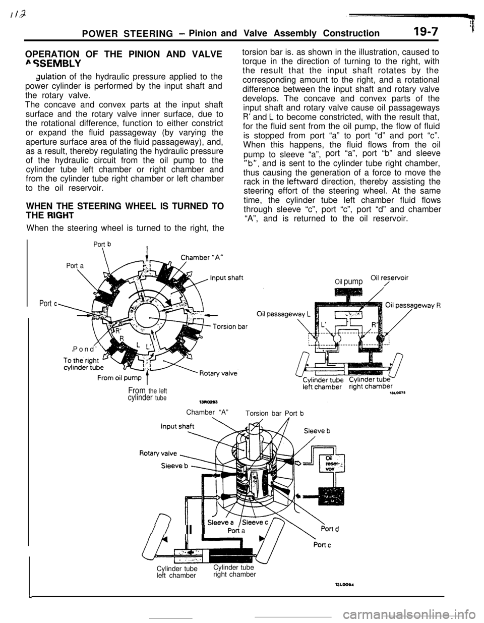
- Pinion and Valve Assembly Construction19-7 ’fOPERATION OF THE PINION AND VALVE
fi %EMBLYdulation of the hydraulic pressure applied to the
power cylinder is performed by the input shaft and
the rotary valve.
The concave and convex parts at the input shaft
surface and the rotary valve inner surface, due to
the rotational difference, function to either constrict
or expand the fluid passageway (by varying the
aperture surface area of the fluid passageway), and,
as a result, thereby regulating the hydraulic pressure
of the hydraulic circuit from the oil pump to the
cylinder tube left chamber or right chamber and
from the cylinder tube right chamber or left chamber
to the oil reservoir.
WHEN THE STEERING WHEEL IS TURNED TOTHE
RIGHTWhen the steering wheel is turned to the right, the
Port b\
Port a\Pond’
Ltorsion bar is. as shown in the illustration, caused to
torque in the direction of turning to the right, with
the result that the input shaft rotates by the
corresponding amount to the right, and a rotational
difference between the input shaft and rotary valve
develops. The concave and convex parts of the
input shaft and rotary valve cause oil passageways
R’ and L to become constricted, with the result that,
for the fluid sent from the oil pump, the flow of fluid
is stopped from port “a” to port “d” and port “c”.
When this happens, the fluid flows from the oil
pump to sleeve “a”,port “a”, port “b” and sleeve
‘lb”, and is sent to the cylinder tube right chamber,
thus causing the generation of a force to move the
rack in the leftward direction, thereby assisting the
steering effort of the steering wheel. At the same
time, the cylinder tube left chamber fluid flows
through sleeve “c”, port “c”, port “d” and chamber
“A”, and is returned to the oil reservoir.
Port c
Oil pumpOil ryetvoir
From the leftcylinder tubeChamber “A”
Torsion bar Port
b
//II YPO< aPond
4Cylinder tube
left chamberCylinder tube
right chamber
Page 218 of 391

POWER STEERING -Pinion and Valve Assembly Construction
WHEN THE STEERING WHEEL IS TURNED TO
THE LEFT
IS-9
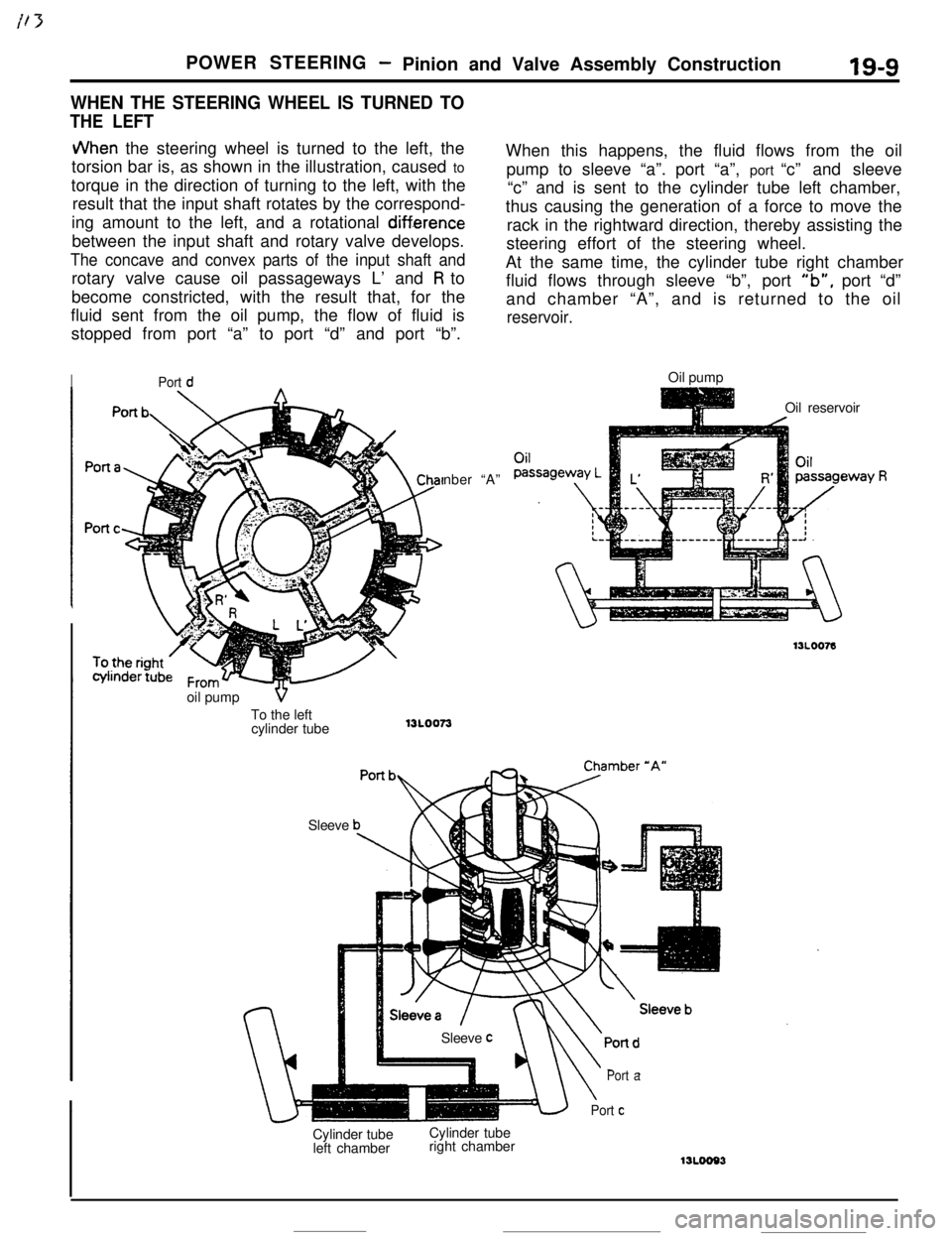
JVhen the steering wheel is turned to the left, the
torsion bar is, as shown in the illustration, caused to
torque in the direction of turning to the left, with the
result that the input shaft rotates by the correspond-
ing amount to the left, and a rotational
diff.erencebetween the input shaft and rotary valve develops.
The concave and convex parts of the input shaft androtary valve cause oil passageways L’ and
R to
become constricted, with the result that, for the
fluid sent from the oil pump, the flow of fluid is
stopped from port “a” to port “d” and port “b”.
IPort dnber “A”
SleeveWhen this happens, the fluid flows from the oil
pump to sleeve “a”. port “a”, port “c” and sleeve
“c” and is sent to the cylinder tube left chamber,
thus causing the generation of a force to move the
rack in the rightward direction, thereby assisting the
steering effort of the steering wheel.
At the same time, the cylinder tube right chamber
fluid flows through sleeve “b”, port
“b”, port “d”
and chamber “A”, and is returned to the oil
reservoir.Oil pump
Oil reservoir
Cylinder tube
left chamberCylinder tube
right chamber
\
Port a
Port cSleeve
coil pump
VTo the left
cylinder tube
13L0073
Page 220 of 391

POWER STEERING- Pinion and Valve Assembly Construction19-9
WHEN THE STEERING WHEEL IS TURNED TO
THE LEFT
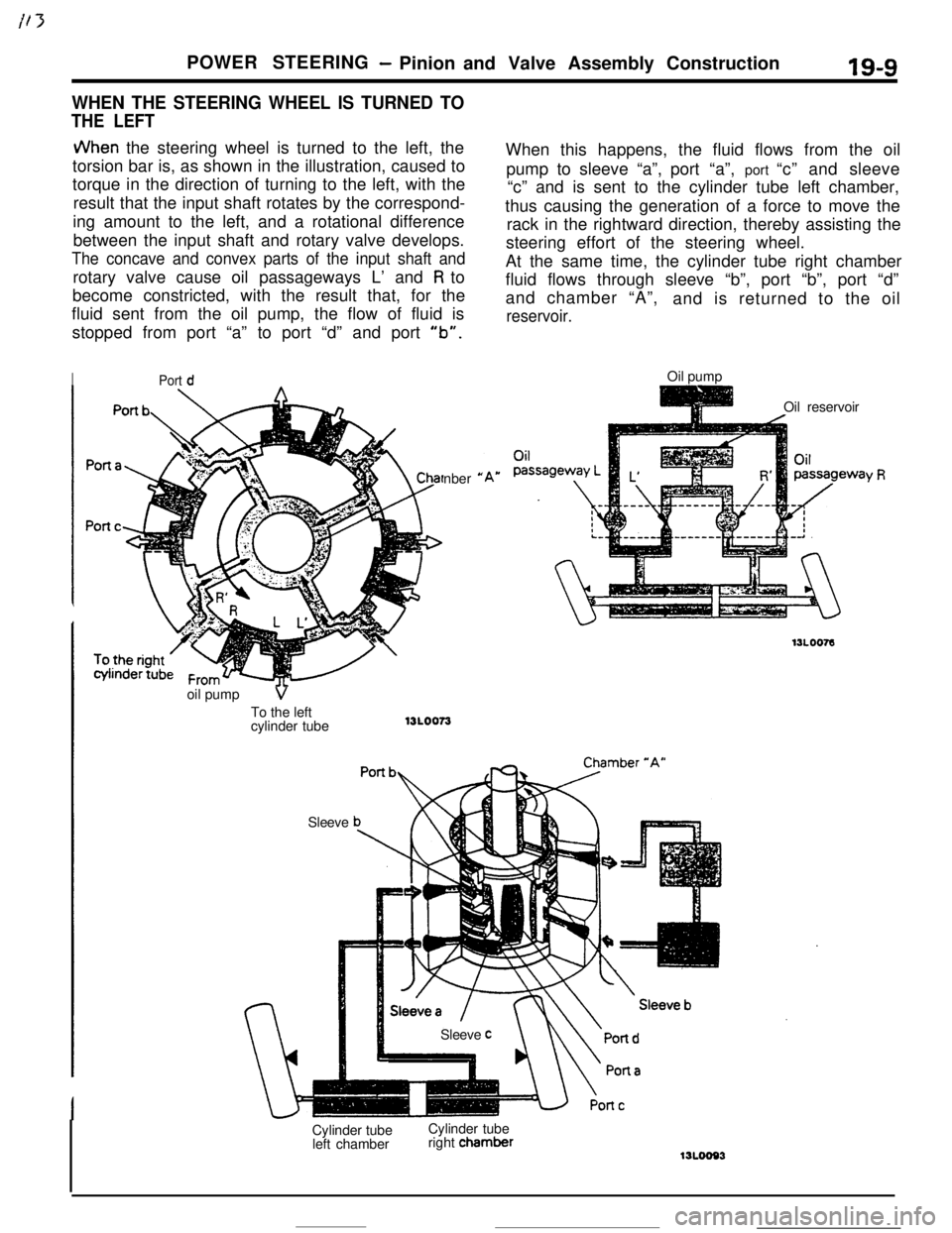
JVhen the steering wheel is turned to the left, the
torsion bar is, as shown in the illustration, caused to
torque in the direction of turning to the left, with the
result that the input shaft rotates by the correspond-
ing amount to the left, and a rotational difference
between the input shaft and rotary valve develops.
The concave and convex parts of the input shaft androtary valve cause oil passageways L’ and
R to
become constricted, with the result that, for the
fluid sent from the oil pump, the flow of fluid is
stopped from port “a” to port “d” and port
“b”.
IPort dnber
*oil pump
VTo the left
cylinder tube13LOO73
SleeveWhen this happens, the fluid flows from the oil
pump to sleeve “a”,port “a”, port “c” and sleeve
“c” and is sent to the cylinder tube left chamber,
thus causing the generation of a force to move the
rack in the rightward direction, thereby assisting the
steering effort of the steering wheel.
At the same time, the cylinder tube right chamber
fluid flows through sleeve “b”, port “b”, port “d”
and chamber “A”,
and is returned to the oil
reservoir.Oil pump
Oil reservoir
Sleeve
cCylinder tube
left chamberCylinder tube
right chamber
‘Y R
Page 224 of 391

i t-7POWER STEERING
- Oil Pump19-13WHEN OIL PUMP OPERATES AT HIGH SPEED
(? -70 RPM OR MORE)
VII, ,dn the pump operation becomes high speed. thethe gear box then is supplied only from the fixed
plunger is pushed further toward the
right than fororifice, with the result that the amount of discharge
medium speed, and both variable orifices close.flow
is reduced to minimum, and, as a result, theFurthermore. the flow-control valve also moves, and
steering effort becomes moderately “heavy”, thus
the bypass port opens wider. The fluid flowing to
providing excellent handling stability at high speed.
Fixed orifice13POO40
OPERATION OF THE RELIEF VALVE
When the A chamber pressure increases when theAs a result of this action, the pressure of the
Bsteering wheel is turned while the vehicle ischamber decreases, and the relief valve closes once
stopped, the
B chamber pressure also increases.again. This action takes place in a moment, and in
and, when the pressure exceeds the relief springthis way, by maintaining the correct balance, the
set load of 8,000 kPa (1,138 psi), the relief valve panmaximum pressure is controlled.
which is closed by a steel ball opens and the fluid
passes through the bypass port and is returned to
the pump’s intake port.
Steel ballRelief sprtngTo steering gear box
/Bypass pan
WPOO41