Page 230 of 391
MANUAL TRANSAXLE <4WD> - General Information
MANUAL TRANSAXLE <4WD>
GENERAL INFORMATION
W5M33 transaxle is a transaxle for 4WD, having
center differential mounted on the output shaft ofwheels. Using the viscous coupling as a device for
the conventional front
wheeledrive type transaxle solimiting differential of the center differential, this
as to distribute drive power to the front and reartransaxle is a full time 4WD type and provides
improved traction and easy drive.
SPECIFICATIONS
Item
Transaxle model
We
Gear ratio
1 St
2nd
3rd4th5th
Reverse
Primary reduction ratio
(number of gear teeth)
Front differential gear ratio
(number of teeth)Specifications
W5M33-2-NPZS
5-speed constant-mesh cable controlled type3.083
1.684
7.1150.833
0.666
3.166
1.275 (37/29).
3.866 (58/l
51
Transfer gear ratio(number of teeth)1.090 (24/22)
Speedometer gear ratio
Oil quantity
liter (qts.)
Transaxle
Transfer
Dry weight ic kg (Ibs.)
29 I36
2.3 (2.43)0.6
(0.63)
64.0(141)
Page 232 of 391
_.c.
21-8MANUAL TRANSAXLE <4WD> - General Information4WD SYSTEM
Viscous couplingCenter differential
cous coupling
kCenth differential
I
IFro& differential
Rear differential
I
I
I [[lll,i, ‘- h-
1 p’f’ ,* , l/i\
/IViscous couplingL
(Option)
3
2210105CONSTRUCTION
OF THE 4WD SYSTEM
The 4WD system configuration and a section of the
center differential are shown above.The viscous coupling for the center differential is
The center differential is placed on the center shaftlocated on rear side of center differential.This
and engine power is transmitted to the front andarrangement makes the entire transaxle simpler a
rear drive shafts by means of a concentric dual shaftmore compact. Differential limiting by the
centc,construction.differential viscous coupling takes place between
the center differential case and the center shaft
(rear wheel drive shaft).
Page 233 of 391

-MANUAL TRANSAXLE
<4WD> - General information
21-9
wer flow is as shown in the chart below. The
.ire power from the engine is first transmitted
through the input shaft and intermediate gear to the
center differential.
The center differential which distributes power to
the front and rear wheels normally operates at a 50
to 50 ratio. As the differential always transmits more
power to the lighter load side, there may be the
case, for example, when one axle is spinning, the
total drive force of the vehicle reduces.
In order to prevent this, the viscous coupling limits
differential action of the center differential accordingto the rotating speed difference between the center
differential case and the center shaft, thereby
securing drive force.
Half of the drive power distributed by the center
differential is transmitted through the front differen-
tial to the front’ drive shaft.
The other half of the drive power distributed by the
center differential is transmitted through the trans-
fer, the propeller shaft and the rear differential to the
rear drive shaft.
DRIVEN BEVEL
REARDIFF~;MfTIAL
,
Page 234 of 391

21-10MANUAL TRANSAXLE <4WD> - General Information4WD SYSTEM OPERATION
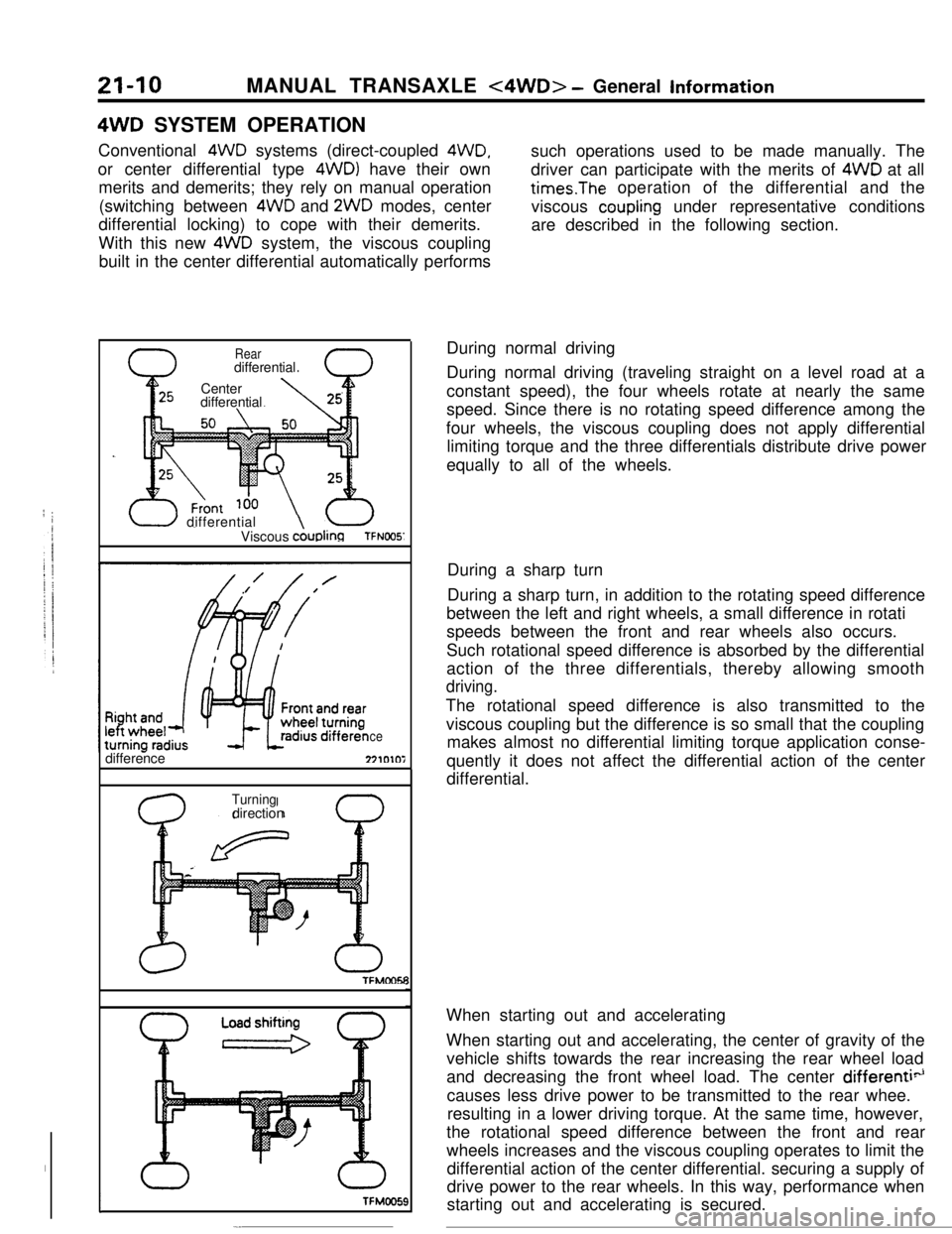
Conventional 4WD systems (direct-coupled
4WD,or center differential type 4WDl have their own
merits and demerits; they rely on manual operation
(switching between 4WD and 2WD modes, center
differential locking) to cope with their demerits.
With this new 4WD system, the viscous coupling
built in the center differential automatically performssuch operations used to be made manually. The
driver can participate with the merits of 4WD at alltimes.The operation of the differential and the
viscous
coupling under representative conditions
are described in the following section.
I
Reardifferential
Center
differential
U differential
Viscous AuDk?TFNOO5’difference
ce271010i
TFMMYTFMMY
0
Turningdirection
ITFMOO!X
-.During normal driving
During normal driving (traveling straight on a level road at a
constant speed), the four wheels rotate at nearly the same
speed. Since there is no rotating speed difference among the
four wheels, the viscous coupling does not apply differential
limiting torque and the three differentials distribute drive power
equally to all of the wheels.
During a sharp turn
During a sharp turn, in addition to the rotating speed difference
between the left and right wheels, a small difference in rotati
speeds between the front and rear wheels also occurs.
Such rotational speed difference is absorbed by the differential
action of the three differentials, thereby allowing smooth
driving.The rotational speed difference is also transmitted to the
viscous coupling but the difference is so small that the coupling
makes almost no differential limiting torque application conse-
quently it does not affect the differential action of the center
differential.
When starting out and accelerating
When starting out and accelerating, the center of gravity of the
vehicle shifts towards the rear increasing the rear wheel load
and decreasing the front wheel load. The center
differenti”causes less drive power to be transmitted to the rear whee.
resulting in a lower driving torque. At the same time, however,
the rotational speed difference between the front and rear
wheels increases and the viscous coupling operates to limit the
differential action of the center differential. securing a supply of
drive power to the rear wheels. In this way, performance when
starting out and accelerating is secured.
Page 235 of 391
MANUAL TRANSAXLE <4WD> - General Information21-I 1When driving on rough roads. . .In case either a front or rear wheel starts spinning on a slippery
or muddy road or when the vehicle is stuck in mud and one tire
spins, the drive power will be decreased by differential action.
However, as this also causes a sharp increase of speed
difference of the viscous coupling, a large differential limiting
torque is now applied, with more power transmitted to the tires
that are not spinning so that the vehicle can drive through or
getout of mud.A
Page 236 of 391
21-12MANUAL TRANSAXLE <4WD> - Viscous Coupling (VCU)
VISCOUS COUPLING (VCU)
RZlL
Seal(X ring)Center shaftCONSTRUCTION
OF VISCOUS COUPLINGThe construction of the viscous coupling
fck the
Within the housing, outer plates (with their outer
center differential is as shown above.
edge fixed to the housing inside splines) and inner
The housing is splinecoupled to the center shaft
plates (with their inner edge fixed to the hub
outF--and the hub is also
spline-coupled to the outputsplines) are arranged alternately.
flange of the center differential case.
The outer plates have spacer rings set between
Therefore, the housing turns with the rear wheel
them on the outer edge in order to space them, and
drive shaft and the hub turns with the center
are fixed to the housing.
differential.
Page 263 of 391

AUTOMATIC TRANSAXLE - Transaxle Mechanism
PARKING MECHANISM
rking sprag (Annulus gear)Detent plateWanual control shaft)
Detent ball
17ooo7When the shift is in the “P” range, the parking pawl
paw1 cannot be moved upward, and the cam, while
engages with the parking sprag provided on outerpressing the spring, collides with the parking
paw1circumference of the
annulus gear to fasten theand the suppon, and is withheld in this condition. If
output shaft, preventing wheels from rotating. Inthe vehicle is moved even slightly in this condition,
other words, when the selector lever is set to thethe turning of wheels causes the
annulus gear to
“P” range, the detent plate and the parking spragturn as well. Since the cam is pressed in the
rod move in the direction of arrow, causing the camdirection of arrow, the parking pawl is pushed up as
on the parking sprag rod to push up the parking paw1a bottom of the sprag aligns with the parking sprag
to engage with the sprag.to engage with the sprag.
In case the parking paw1 collides against a crest of
the sprag, only the rod moves because the parkingIn this way, the parking mechanism eliminates any
chances of the vehicle from being idly moved.
Page 321 of 391

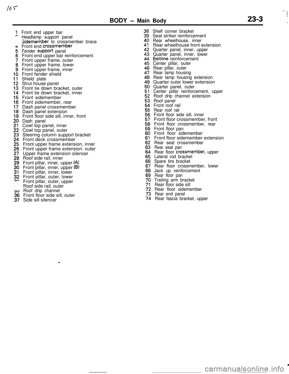
BODY - Main Body23-3 \
Front end upper bar
Headlamp support panelsidemember
to crossmember braceFront end crossmember
Fender suppoR panelFront end upper bar reinforcement
Front upper frame, outer
Front upper frame, lower
Front upper frame, inner
Front fender shield
Shield plateStrut house panel
Front tie down bracket, outer
Front tie down bracket, inner
Front sidemember
Front sidemember, rear
Dash panel crossmember
Dash panel extension
Front floor side sill, inner, front
Dash panelCowl top panel, inner
Cowl top panel, outer
Steering column support bracket
Front deck crossmember
Front upper frame extension, inner
Front upper frame extension. outer
Upper frame extension silencer
Roof side rail, inner
Front pillar, inner, upper
(A)Front pillar, inner, upper (B)Front pillar, inner, lower
Front pillar, outer, lower
Front pillar, outer, upper
Roof side rail, outer
Roof drip channelFront floor side sill, outer
Side sill silencer
Shelf corner bracketSeat striker reinforcement
Rear wheelhouse, innerRear wheelhouse front extension
Quarter panel, inner, upper
Quarter panel, inner, lower
Beltline reinforcementCenter pillar, outer
Rear pillar, outer
Rear lamp housing
Rear lamp housing extensionQuarter outer lower extension
Quarter panel, outer
Center pillar reinforcement, upper
Roof drip channel extension
Roof panel
Front roof rail
Rear roof railFront floor side sill, innerFront floor crossmember, front
Front floor crossmember, rear
Front floor pan
Front floor sidememberFront floor sidemember extension
Rear seat crossmemberRear seat panRear floor crossmember, upper
Lateral rod bracket
Spare tire bracket
Rear floor crossmember, lower
Jack up reinforcement
Rear floor panTrailing arm bracket
Rear floor side sill
Rear floor sidemember
Rear end panelRear fascia bracket, upper
c
c