Page 274 of 391

21-50AUTOMATIC TRANSAXLE - Transaxle Control
Vehicle
sensorspeedTerminal voltage
(VI
1
5
\*Fluidtemperature
02080PCI 1750409VEHICLE-SPEED SENSOR
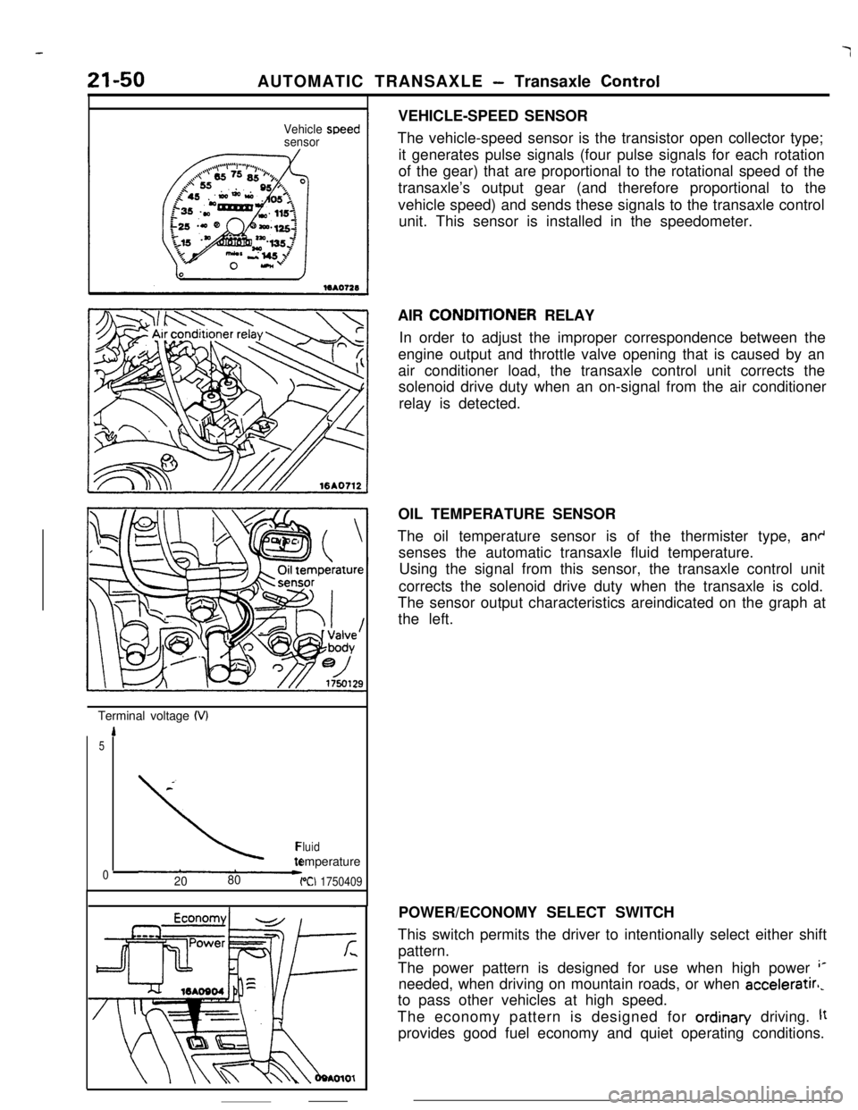
The vehicle-speed sensor is the transistor open collector type;
it generates pulse signals (four pulse signals for each rotation
of the gear) that are proportional to the rotational speed of the
transaxle’s output gear (and therefore proportional to the
vehicle speed) and sends these signals to the transaxle control
unit. This sensor is installed in the speedometer.
AIR CONDlTlONER RELAY
In order to adjust the improper correspondence between the
engine output and throttle valve opening that is caused by an
air conditioner load, the transaxle control unit corrects the
solenoid drive duty when an on-signal from the air conditioner
relay is detected.
OIL TEMPERATURE SENSOR
The oil temperature sensor is of the thermister type,
an+senses the automatic transaxle fluid temperature.
Using the signal from this sensor, the transaxle control unit
corrects the solenoid drive duty when the transaxle is cold.
The sensor output characteristics areindicated on the graph at
the left.
POWER/ECONOMY SELECT SWITCH
This switch permits the driver to intentionally select either shift
pattern.
The power pattern is designed for use when high power
‘*needed, when driving on mountain roads, or when acceleratirl,
to pass other vehicles at high speed.
The economy pattern is designed for ordinan/ driving.
ltprovides good fuel economy and quiet operating conditions.
Page 374 of 391

25-2EMISSION CONTROL SYSTEMS - General Information
GENERAL INFORMATION
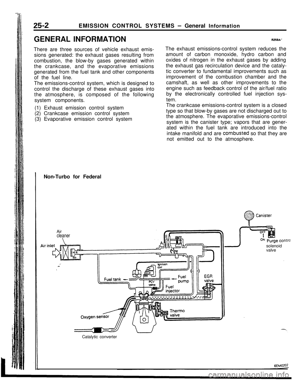
There are three sources of vehicle exhaust emis-
sions generated: the exhaust gases resulting from
combustion, the blow-by gases generated within
the crankcase, and the evaporative emissions
generated from the fuel tank and other components
of the fuel line.
The emissions-control system, which is designed to
control the discharge of these exhaust gases into
the atmosphere, is composed of the following
system components.
(1) Exhaust emission control system
(2) Crankcase emission control system
(3) Evaporative emission control system
R258A’The exhaust emissions-control system reduces the
amount of carbon monoxide, hydro carbon and
oxides of nitrogen in the exhaust gases by adding
the exhaust gas recirculation device and the cataly-
tic converter to fundamental improvements such as
improvement of the combustion chamber and the
camshaft, as well as other improvements to the
engine such as feedback control of the air/fuel ratio
by the electronically controlled fuel injection sys-
tem.
The crankcase emissions-control system is a closed
type so that blow-by gases are not discharged out to
the atmosphere. The evaporative emissions-control
system is the canister type; vapors that are gener-
ated within the fuel tank are introduced into the
intake manifold and are combusted so that they are
not emitted out to the atmosphere.
Non-Turbo for Federal
Air
cleaner
\solenoid
valve
Catalytic converter
:
0
$2:) Canister:.:
Page 376 of 391

--.
25-2EMISSION CONTROL SYSTEMS - General Information
GENERAL INFORMATION
There are three sources of vehicle exhaust emis-
sions generated: the exhaust gases resulting from
combustion, the blow-by gases generated within
the crankcase, and the evaporative emissions
generated from the fuel tank and other components
of the fuel line.
The emissions-control system, which is designed to
control the discharge of these exhaust gases into
the atmosphere,is composed of the following
system components.
(1) Exhaust emission control system
(2) Crankcase emission control system
(3) Evaporative emission control system
RZSBAThe exhaust emissions-control system reduces the
amount of carbon monoxide, hydro carbon and
oxides of nitrogen in the exhaust gases by adding
the exhaust gas recirculation device and the cataly-
tic converter to fundamental improvements such as
improvement of the combustion chamber and the
camshaft, as well as other improvements to the
engine such as feedback control of the air/fuel ratio
by the electronically controlled fuel injection sys-
tem.
The crankcase emissions-control system is a closed
type so that blow-by gases are not discharged out to
the atmosphere. The evaporative emissions-control
system is the canister type; vapors that are gener-
ated within the fuel tank are introduced into the
intake manifold and are combusted so that they are
not emitted out to the atmosphere.
Non-Turbo for Federal
.;. :
0
.%??? CanisterAir
cleaner
\valveOxygenFuel tank
-a I”’ ,T
sensr’
Catalytic converter
6EMO?O2
Page 383 of 391

---- .~ _ _EMISSION CONTROL SYSTEMS
- Catalytic Converter I Air-fuel Mixture Ratio Control System25-9
,ATALYTlC CONVERTERRZXIAAAThe catalytic converter is installed on the middle ofand surrounded by a stainless steel shell.
the exhaust pipe under the floor.The catalytic converter oxidizes carbon monoxide
This catalytic converter uses a monolithic type
catalyst with a honeycomb structure that has itsand hydrocarbon, and reduces oxides of nitrogen.
surface coated with catalytic components. Thewhich are present in the exhaust gas, in order to
minimize their emission levels.
catalyst is supported by a stainless steel wire mesh
Exhaust air
3Stainlesssteei shell
\CoverStainless steel wire mesh
lEM0031
AIR-FUEL MIXTURE RATIO CONTROL
SYSTEMThe
MPI system is a system which employs the signals from
the oxygen sensor to activate and control the injector installed
at the each cylinder head thus precisely regulating the air-fuel
mixture ratio and reducing emissions,
This in turn allows the engine to produce exhaust gases of the
proper composition to permit the use of a three-way catalytic
converter. The three-way catalytic converter is designed to
convert the three pollutants
(1) hydrocarbons (HC), (2) carbon
monoxide (CO), and
(3) oxides of Nitrogen (NOx) into harmiess
substances.There are two operating modes in the
MPI system:
(1) Open Loop
Air-fuel ratio is controlled by information programmed into
the engine control unit at manufacture.
(2) Closed Loop
Air-fuel ratio is varied by the engine control unit based on
information supplied by the oxygen sensor.
NOTEFor detailed information concerning the
MPI system, refer
to Fuel System.