1989 MITSUBISHI GALANT air filter
[x] Cancel search: air filterPage 386 of 1273
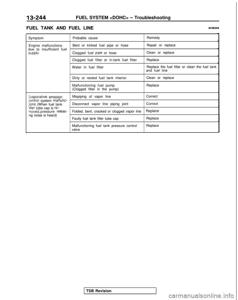
13-244FUEL SYSTEM
FUEL TANK AND FUEL LINE
MlBEAAh
Symptom Probable cause Remedy
Engine malfunctions Bent or kinked fuel pipe or hose Repair or replace
due to insufficient fuel supply
Clogged fuel pipe
or hose Clean or replace
Clogged fuel filter or in-tank fuel filter Replace
Water in fuel filter Replace the fuel filter or clean the fuel tank
and fuel line
Dirty or rested fuel tank interior
Malfunctioning fuel pump
(Clogged filter in the pump) Clean or replace
Replace Zvaporative
emission Mispiping of vapor line
Correct
:ontrol system malfunc-:ions (When fuel tank
Disconnect vapor line piping joint
Correct‘iller tube cap is re-noved, pressure releas-
Folded, bent, cracked or clogged vapor lineReplaceng noise is heard)
Faulty fuel tank filler tube cap
Malfunctioning fuel tank pressure control
valve Replace
Replace
TSB Revision
I
Page 403 of 1273
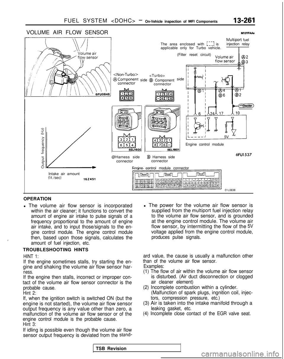
FUEL SYSTEM
VOLUME AIR FLOW SENSORMlWFAAs
/
side
@Harness side connector
I@ Harness sideconnector
Fnnine control module connector
Multiport fuel
The area enclosed with :I: is injection relay
applicable only for Turbo vehicle.
I
@I Component connector (Filter reset circuit)
Engine control module
6FU1537
Intake air amount (Wsec)
162451
OlLO838
OPERATION
l The volume air flow sensor is incorporated
within the air cleaner; it functions to convert the
amount of engine air intake to pulse signals of a
frequency proportional to the amount of engine air intake, and to input those/signals to the en-
gine control module. The engine control module
then, based upon those signals, calculates the
amount of fuel injection, etc.
TROUBLESHOOTING HINTS
HINT 1:
If the engine sometimes stalls, try starting the en-
gine and shaking the volume air flow sensor har-
ness.
If the engine then stalls, incorrect or improper con-
tact of the volume air flow sensor connector is the
probable cause.
Hint 2:
If, when the ignition switch is switched ON (but the
engine is not started), the volume air flow sensor
output frequency is any value other than zero, a
malfunction of the volume air flow sensor or of the
engine control module is the probable cause.
Hint 3:
If idling is possible even though the volume air flow
sensor output frequency is deviated from the
stand-
l The power for the volume air flow sensor is supplied from the
multiport fuel injection relay
to the volume air flow sensor, and is grounded
at the engine control module. The volume air
flow sensor, by intermitting the flow of the
5V
voltage applied from the engine control module,
produces pulse signals.
ard value, the cause is usually a malfunction other
than of the volume air flow sensor. Examples:
(1) The flow of air within the volume air flow sensor
is disturbed. (Air duct disconnection or clogged
air cleaner element)
(2) Incomplete combustion within a cylinder.(Malfunction of spark plugs, ingnition coil, injec-
tors, compression pressure, etc.)
(3) Air is taken into the intake manifold through a
leaking gasket, etc.
(4) Incomplete close contact of the EGR valve seat.
TSB Revision
Page 455 of 1273
FUEL SYSTEM
of MFI
Components13-313
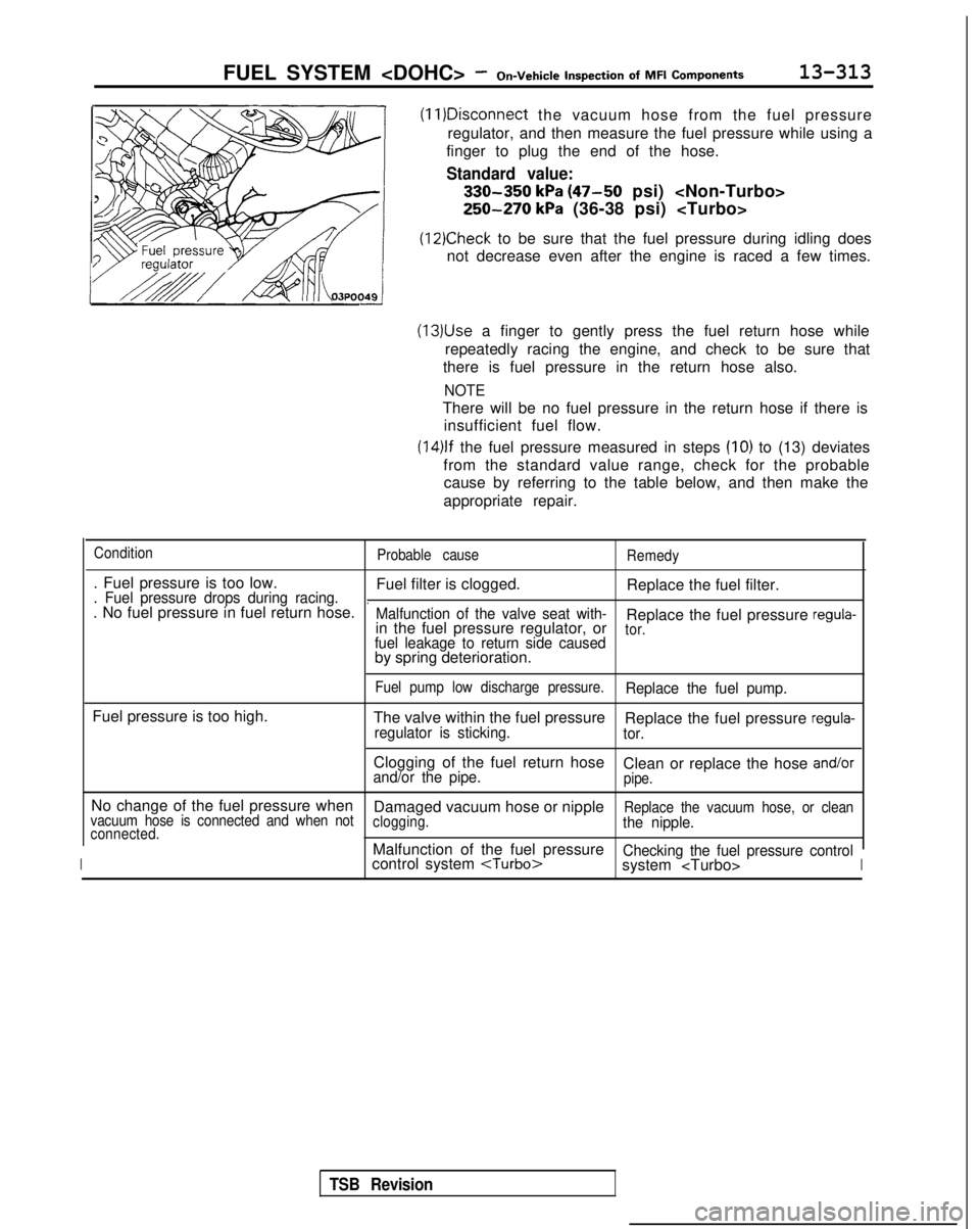
(11)Disconnect
the vacuum hose from the fuel pressure
regulator, and then measure the fuel pressure while using a
finger to plug the end of the hose.
Standard value:
330-350 kPa (47-50 psi)
250-270 kPa (36-38 psi)
(12)Check to be sure that the fuel pressure during idling does
not decrease even after the engine is raced a few times.
(13)Use a finger to gently press the fuel return hose while
repeatedly racing the engine, and check to be sure that
there is fuel pressure in the return hose also.
NOTE
There will be no fuel pressure in the return hose if there is insufficient fuel flow.
(14)lf the fuel pressure measured in steps (IO) to (13) deviates
from the standard value range, check for the probable cause by referring to the table below, and then make the
appropriate repair.
Condition Probable causeRemedy
. Fuel pressure is too low.
Fuel filter is clogged.Replace the fuel filter.. Fuel pressure drops during racing... No fuel pressure in fuel return hose.Malfunction of the valve seat with-Replace the fuel pressure regula-in the fuel pressure regulator, ortor.fuel leakage to return side causedby spring deterioration.
Fuel pump low discharge pressure.Replace the fuel pump.
Fuel pressure is too high.
The valve within the fuel pressureReplace the fuel pressure regula-regulator is sticking. tor.
Clogging of the fuel return hose
Clean or replace the hose and/orand/or the pipe.pipe.
No change of the fuel pressure when Damaged vacuum hose or nippleReplace the vacuum hose, or clean
vacuum hose is connected and when not clogging.the nipple.connected.
IMalfunction of the fuel pressureChecking the fuel pressure controlcontrol system
system
TSB Revision
Page 595 of 1273
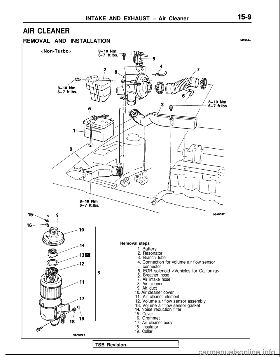
INTAKE AND EXHAUST - Air Cleaner1’5-9
AIR CLEANER
REMOVAL AND INSTALLATIONMlSFA-
6-7 ft.lbs.
IKIII
I
I/I /
I, s;qr
ii--l-
-
05AOO97
Removal steps
1. Battery2. Resonator3. Branch tube4. Connection for volume air flow sensor
B
connector5. EGR solenoid
7. Air intake hose
8.Air cleaner9.Air ductIO. Air cleaner cover11. Air cleaner element12. Volume air flow sensor assembly
13. Volume air flow sensor gasket
14. Noise reduction filter
15.Cover16.Grommet
17. Air cleaner body
18.Insulator19.Collar
TSB RevisionI
Page 596 of 1273
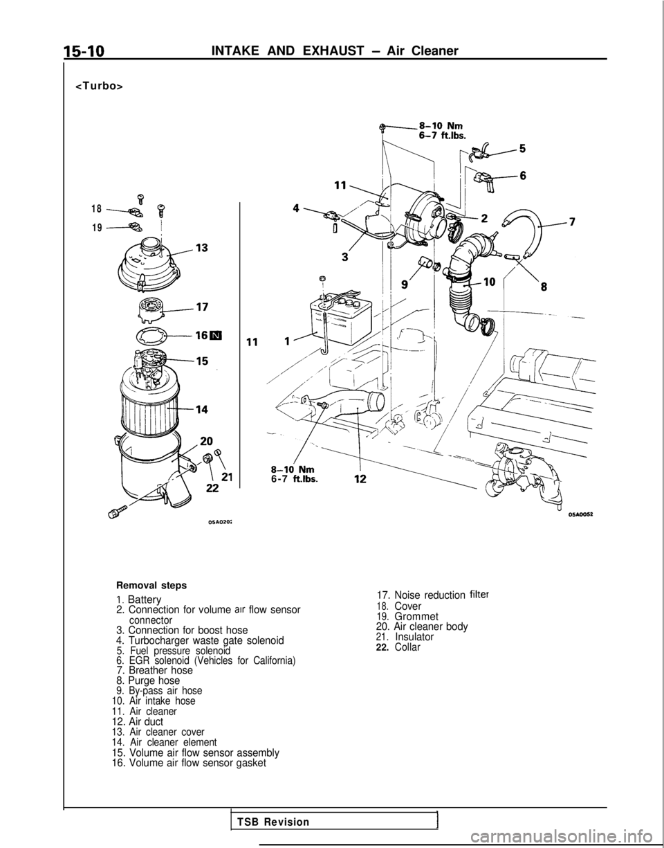
15-10INTAKE AND EXHAUST - Air Cleaner
~8-10 Nm
K nlbF+5
18 19
!\/ ~2%6
Td4fba5-9 /z-l
8-k Nm6-7 ft.lbs.
Removal steps
I. Battery2. Connection for volume arr flow sensorconnector3. Connection for boost hose
4. Turbocharger waste gate solenoid
5. Fuel pressure solenoid
6. EGR solenoid (Vehicles for California)
7. Breather hose
8. Purge hose
9. By-pass air hose
10. Air intake hose
11. Air cleaner
12. Air duct13. Air cleaner cover
14. Air cleaner element
15. Volume air flow sensor assembly
16. Volume air flow sensor gasket 17. Noise reduction
filter
18.Cover19.Grommet
20. Air cleaner body
21.Insulator
22.Collar
TSB Revision
Page 761 of 1273
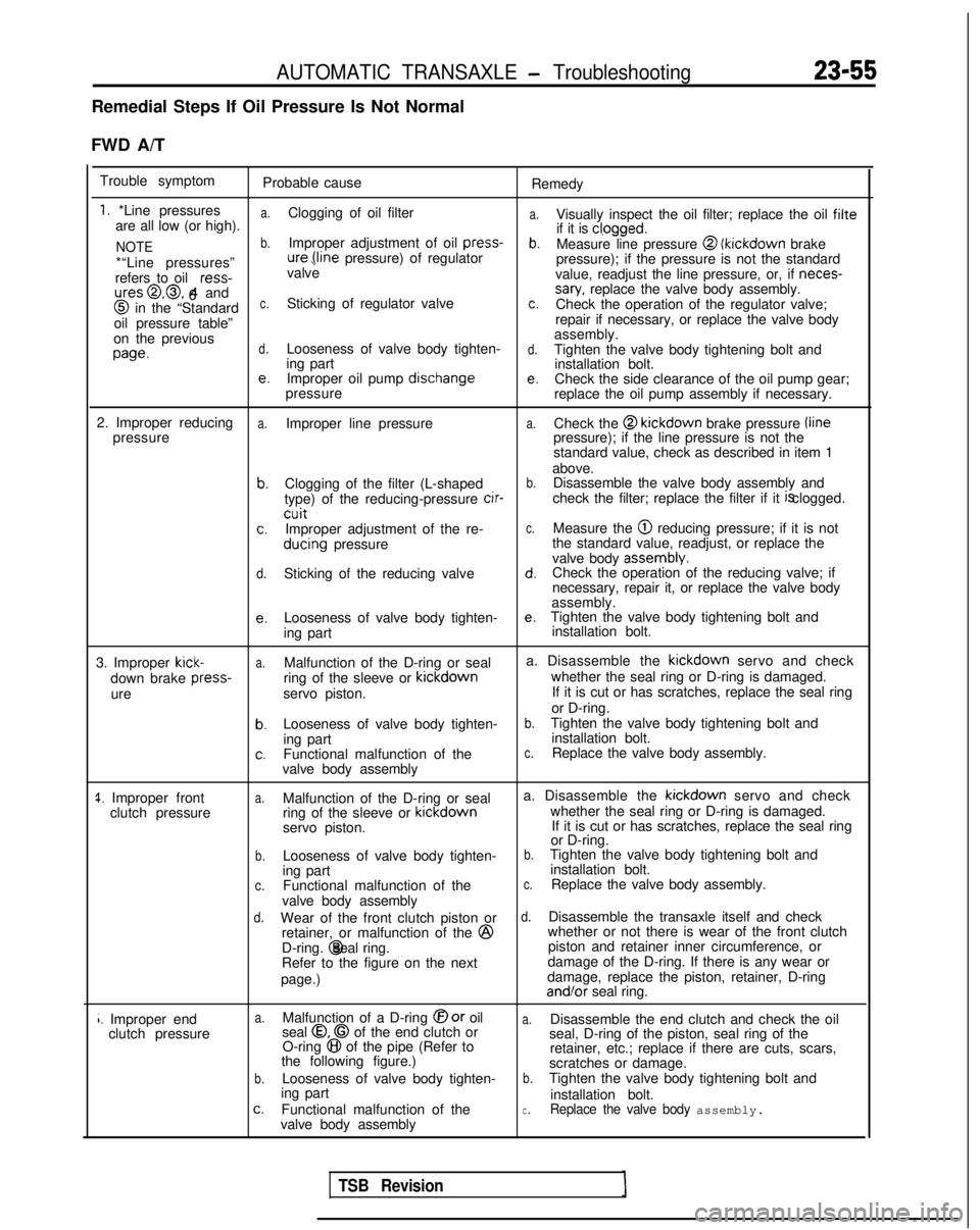
AUTOMATIC TRANSAXLE - Troubleshooting23-55
Remedial Steps If Oil Pressure Is Not Normal
FWD A/T Trouble symptom Probable cause Remedy
1. *Line pressuresa.
a.are all low (or high).Clogging of oil filter
Visually inspect the oil filter; replace the oil filte
NOTEb.Improper adjustment of oil press-
if it is cl,ogged.b.Measure line pressure @ (kickdown
brake
*“Line pressures” ure,(line
pressure) of regulator
pressure); if the pressure is not the standard
refers to oil ress-
valve
value, readjust the line pressure, or, if neces-
ures@,@, 4 and
6sary, replace the valve body assembly. @
in the “Standardc.Sticking of regulator valvec.Check the operation of the regulator valve;
oil pressure table” repair if necessary, or replace the valve body
on the previous assembly.
wed.Looseness of valve body tighten-d.Tighten the valve body tightening bolt and
ing part installation bolt.
e.Improper oil pump dischangee.Check the side clearance of the oil pump gear;
pressure replace the oil pump assembly if necessary.
2. Improper reducing
a.Improper line pressurea.Check the @ kickdown
brake pressure /line
pressure pressure); if the line pressure is not the
standard value, check as described in item 1
above.
b.Clogging of the filter (L-shapedb.Disassemble the valve body assembly and
type) of the reducing-pressure cir-
check the filter; replace the filter if it is clogged.
cuitc.Improper adjustment of the re-c.Measure the @ reducing pressure; if it is not
ducing
pressure the standard value, readjust, or replace the
valve body assembly.
d.Sticking of the reducing valved.Check the operation of the reducing valve; if
necessary, repair it, or replace the valve body
assembly.
e.Looseness of valve body tighten-e.Tighten the valve body tightening bolt and
ing part installation bolt.
3. Improper
kick-a.Malfunction of the D-ring or seal a. Disassemble the kickdown
servo and check
down brake press-
ring of the sleeve or kickdown
whether the seal ring or D-ring is damaged.
ure servo piston. If it is cut or has scratches, replace the seal ring
or D-ring.
b.Looseness of valve body tighten-b.Tighten the valve body tightening bolt and
ing part installation bolt.
c.Functional malfunction of thec.Replace the valve body assembly.
valve body assembly
1. Improper front clutch pressurea.Malfunction of the D-ring or seal a. Disassemble the kickdown
servo and check
ring of the sleeve or kickdown
whether the seal ring or D-ring is damaged.
servo piston. If it is cut or has scratches, replace the seal ring
or D-ring.
b.Looseness of valve body tighten-b.Tighten the valve body tightening bolt and
ing part installation bolt.
c.Functional malfunction of thec.Replace the valve body assembly.
valve body assembly
d.Wear of the front clutch piston ord.Disassemble the transaxle itself and check
retainer, or malfunction of the @
whether or not there is wear of the front clutch
D-ring. @ seal ring.
piston and retainer inner circumference, or
Refer to the figure on the next damage of the D-ring. If there is any wear or
page.) damage, replace the piston, retainer, D-ring and/or
seal ring.
i. Improper end
clutch pressurea.Malfunction of a D-ring @or oila.Disassemble the end clutch and check the oil
seal 0.0 of the end clutch or
O-ring 8 of the pipe (Refer to seal, D-ring of the piston, seal ring of the
the following figure.) retainer, etc.; replace if there are cuts, scars,
scratches or damage.
b.Looseness of valve body tighten-b.Tighten the valve body tightening bolt and
ing part installation bolt.
c.Functional malfunction of thec.Replace the valve body assembly.valve body assembly
TSB Revision
Page 1178 of 1273
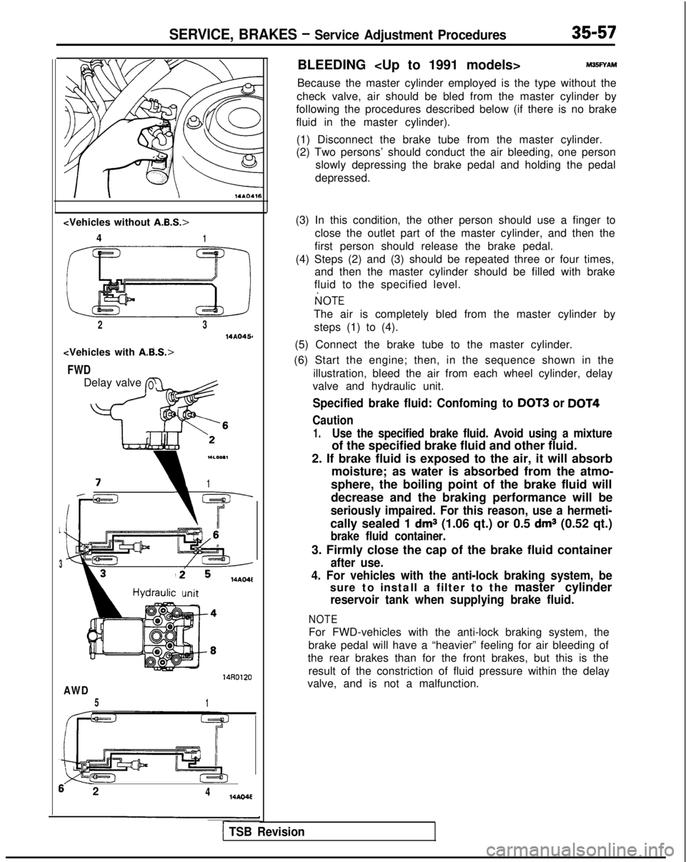
SERVICE, BRAKES - Service Adjustment Procedures35-57
4
1
2314AQ456
FWD
Delay valve L
flc ’
-c
i1
L
3
14AO4l
mit
14RD120
AWD
51
6 2414AO4E
BLEEDING
Because the master cylinder employed is the type without the
check valve, air should be bled from the master cylinder by
following the procedures described below (if there is no brake
fluid in the master cylinder).
(1) Disconnect the brake tube from the master cylinder.
(2) Two persons’ should conduct the air bleeding, one person
slowly depressing the brake pedal and holding the pedal
depressed.
(3) In this condition, the other person should use a finger to close the outlet part of the master cylinder, and then the
first person should release the brake pedal.
(4) Steps (2) and (3) should be repeated three or four times, and then the master cylinder should be filled with brake
fluid to the specified level.
I(]OTE
The air is completely bled from the master cylinder by
steps (1) to (4).
(5) Connect the brake tube to the master cylinder.
(6) Start the engine; then, in the sequence shown in the illustration, bleed the air from each wheel cylinder, delay
valve and hydraulic unit.
Specified brake fluid: Confoming to DOT3 or DOT4
Caution
1.Use the specified brake fluid. Avoid using a mixture
of the specified brake fluid and other fluid.
2. If brake fluid is exposed to the air, it will absorb moisture; as water is absorbed from the atmo-
sphere, the boiling point of the brake fluid will
decrease and the braking performance will be
seriously impaired. For this reason, use a hermeti-
cally sealed 1 dms (1.06 qt.) or 0.5 dms (0.52 qt.)
brake fluid container.
3. Firmly close the cap of the brake fluid container
after use.
4. For vehicles with the anti-lock braking system, be
sure to install a filter to the master cylinder
reservoir tank when supplying brake fluid.
NOTE
For FWD-vehicles with the anti-lock braking system, the
brake pedal will have a “heavier” feeling for air bleeding of
the rear brakes than for the front brakes, but this is the
result of the constriction of fluid pressure within the delay
valve, and is not a malfunction.
1 TSB Revision
Page 1264 of 1273
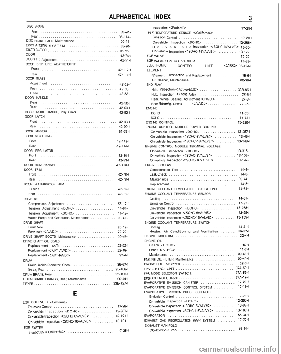
ALPHABETICAL INDEX3
DISC BRAKEFront
......................................
.
35-94-I
Rear......................................
.
35-114-l
DlSC BRAKE PADS. Marntenance.......................
.
00-44-j
DWHARGlNG
SYSTEM ......................... 55-26-l
DISJRIBUTOR..............................
.
16-55-11
DOoR
........................................
42-74-lDOOR. Fit Adjustment
..............................
. 42-51-l
DOOR DRIP LINE WEATHERSTRIP
Front.......
.
........................... 42-112-j
Rear.....................................
.
42-114-IDOOR GLASS
Adjustment
...............................
42-52-f
Front..................................
.
42-80-l
Rear ........... 42-83-I
DOOR HANDLE
Front
...........
.
........ ............ 42-96-l
Rear.
.................. ................. 42-99-l
DOOR INSIDE HANDLE, Play Check.....................
.
42-52-l
DOOR LATCH
Front
.........
.
............... ........ 42-96-l
Rear.................................
. 42-99-l
DOOR MIRROR...............................
.
51-33-1
DOOR
MOULDING
Front
....................................
.
42-112-l
Rear......................................
.
42-114-l
DOOR REGULATOR
Front
......................................
.
42-80-I
Rear...............
.
.................... 42-83-l
DOOR RUNCHANNEL..........................
.
42-l 10-l
DOOR TRIM
Front
......................................
.
42-76-l
Rear.......................................
.
42-78-i
DOOR WATERPROOF FILM
Fron
t
.................................... 42-76-l
Rear........................................
.
42-78-l
DRIVE BELT
Compressor, Adjustment
....................
.
55-17-l
Tension Adjustment
Tension Adjustment
Water Pump and Generator, Maintenance ..............
00-41 -IDRIVE SHAFTFront Axle
.....................................
. 26-12-l
Rear
Axle
. 27-20-I
DRIVE SHAFT BOOTS, Maintenance....................
.
00-45-j
DRIVE SHAFT OIL SEALSReplacement
...........................
.
23-92-I
Replacement
.
22-18-l
Replacement
.
22-4-l
DRUMBrake, inside Diameter, Check
......................
.
35-67-j
Brake,
Rear..............................
.
..... 35-108-l
DRUM BRAKE, Rear
................................
.
35-108-1
DRUM BRAKE LININGS, Rear, Maintenance
..............
.
06-44-j
DRYER........................................
.
33B-127-l
E
EGR SOLENOID
.................................
.
17-28-j
On-vehicle
Inspection
On-vehicle
Inspection
.
13-101-t
On-vehicle
Inspection
.
13-191-l
EGR SYSTEM
speccon
.
17-25-j inspection
.
17-25-1
EGR TEMPERATURE SENSOR
Emission Control
................................
.
17-28-l
On-vehicle Inspection
On-vehicle Inspection
On-vehicle
Inspection
.
13-177-l
EGRVALVE........................................
.
17-27-f
EGR VALVE CONTROL VACUUM
.......................
.
17-26-l
ELECTRONIC CONTROL UNIT
35-134-jELEMENT
Air Cleaner. Inspection
and Replacement ................ 15-6-l
Air Cleaner, Maintenance ........................... go-39-j
END PLAY
Hub.
Inspection
.
33B-86-l
Hub. Inspection
.
26-5-l
Rear. Wheel Bearing, Adjustment
.
27-3-l
Rear Wheel Bearing. Check
.
27-15-i
ENGINE
DOHC
.......................................
.
11-63-l
SOHC.......................................
.
11-14-1
ENGINE CONTROL................................
.
13-328-l
ENGINE CONTROL MODULE POWER GROUND
On-vehicle Inspectron
..................
.
13-257-l
On-vehicle Inspection
.
13-45-l
On-vehicle Inspection
.
13-146-1
ENGINE CONTROL MODULE TERMINAL VOLTAGE
On-vehicle Inspection
.
13-315-I
On-vehicle Inspection
On-vehicle Inspection
.
13-192-l
ENGINE COOLANT
Concentration Test
....
.
............................
14-8-l LeakCheck
....................................... 14-8-l
Maintenance ..................................... 00-44-I
Replacement ..............................
,......
.
14-8-I
ENGINE COOLANT TEMPERATURE GAUGE UNIT.........
. 14-31-l
ENGINE COOLANT TEMPERATURE SENSOR
Cooling
........................................
. 14-31-I
Emission Control .................................. 17-21-l
On-vehicle Inspection
On-vehicle Inspection
.
13-55-j
On-vehicle Inspection
.
13-155-l
ENGINE COOLANT TEMPERATURE SWITCH
Cooling........................................
. 14-31-I
Heater, Air Conditioning and Ventilation ......... 55-57-l
ENGINE MOUNTING..................................
.
32-4-l
ENGINE OILCheck
................................
.
11-57-j
Check
. 11-7-l
Maintenance .....................................
00-41-1
ENGINE OIL FILTER, Maintenance ......................
.
60-41-j
ENGINE RPLL
STOPPER..............................
.
32-6-j
EPS CONTROL UNIT................................
.
37A-59-l
EPS MODE SELECTOR SWITCH.......................
.
37A-59-j
EpS SOLENOID, Check
..............................
.
37A-19-j
EVAPORATIVE EMISSION CANISTER...................
.
77-21-j
EVAPORATIVE EMISSION CONTROL SYSTEM............
.
17-15-l
EVAPORATIVE EMISSION PURGE SOLENOIDEmission Control
.................................
.
17-21-1
On-vehicle
Inspection
, 13-307-I
On-vehicle
Inspection
.
13-99-1
On-v&i&
inspection
........... 13-189-j
EVAPORATOR....
.
................................ 55-34-f
EXHAUST GAS RECIRCULATION (EGR) SYSTEM..........
.
17-22-I
EXHAUST MANIFOLD
DOHC-Non-Turbo................................
.
15-30-1